Please help tune this crossover

I have built a 3-way speaker consisting of two 8" Peerless woofers, two Vifa NE123W-08 midranges, and a Satori TW29RN-8 tweeter. The woofers are in their own bass bins, with mids and tweeter in separate enclosures. The woofer is crossed actively, the mids and tweeters passively with this professionally designed xover. The designer is no longer available to assist me, so I ask for your suggestions on where to start tweaking this system.

The speakers are rather dull and congested, with lifeless upper midrange. The soundstage is adequate, but voices seem to stay inside the enclosure and are somewhat muffled. When I first purchased them, I ran the midranges full range by themselves, with the same active xover on the woofers. Even without a tweeter, the system was lively and present, perhaps a bit too bright and raggedy on top. Now it seems that the upper midrange is missing. I've tried reducing the tweeter pad, but that doesn't change much other than making music sound etched and screechy. I think the problem lies in the upper response of the midrange, but I don't know what to try. I have also tried swapping tweeter leads in case the phase was inverted, but, as expected, that makes it worse. The xover components are very high quality; no corners cut there. The mids/tweeter amp is superb, the wiring is also high quality.

The midrange drivers are wired in parallel. I am wired to take action if given some direction.

Peace,
Tom E

Attachments

Aurum Cantus G1 ribbon tweeters - MINT

hello everyone...

just what it says.. a pair of Aurum Cantus G1 ribbon tweeters... their top of the line, to my understanding... about two years old, but only used for less than two hours... they went into a prototype and were just a few dB short of matching up with the horns below them... we decided we did not want to pad down the horns, and therefore elected to go with a horn tweeter... so here they are..

like new.. literally.. zero scratches that I could find.. I have the non-marring ribbon covers for shipping and storing.. original boxes.. even the little blue and red connectors unused... we just used clip leads... :^)

list retail is US$1500/pair.... Parts Express moves them for $600/pair... I am asking US$450 obo... (make me an offer)..

shipping paid by buyer.. 18 pounds from US 12572... New York...

thanks!

Jeffrey

oh! direct email is best as the notifications do not seem to be coming through..

experiencemusic _at_ hotmail _dot_ com

Attachments

  • IMG_8617.JPG
    IMG_8617.JPG
    176.5 KB · Views: 385
  • IMG_8615.JPG
    IMG_8615.JPG
    110.5 KB · Views: 355
  • IMG_8616.JPG
    IMG_8616.JPG
    162.2 KB · Views: 353
  • IMG_8618.JPG
    IMG_8618.JPG
    121.4 KB · Views: 345

small speaker driver for a T-line any suggestions ?

Hi,
I´m still looking for a suitable driver unit, the ons i considerd soo far are:
TEBM35C10
View attachment TEBM35C10-4_Rev-1.8.pdf
TA6FD00-04/08
View attachment Peerless_TA6FD00-08.pdf//View attachment Peerless_TA6FD00-04.pdf
Wuld be interested on your opinion on this drivers for use in a t-line desing.


And now my final request, do you have any suggestions wich driver i shuld use//consider the driver shuld be able to be mounted on a 65*65mm surface.


thanks in advance, Any input is much appreciated
have a nice day

Motus? SB?

At the purely concept stage of building myself some large three way sealed cabinet (in fact three sealed cabinet, Naim style) active speakers.

I haven't played this game for forty years. Prejudices, I like simple crossovers, metal domed tweeters, and low distortion and transient handling come before a flat frequency response. I like things designed in the first world and built in the third. Best speaker I ever owned, Epos ES14s. Taken out by lightening.

Units have to be readily available in Europe (mainland, not UK).

I like the idea of the SB metal domed tweeter. What's a good brand of mid and bass to go with that? Or is it not as good as it looks? Motus look nice for the mid, but I'm struggling to find a suppler.

Tweeter, mid, bass, for punch and low distortion, high end but not silly. What are the fancied runners and riders these days?

FS: DaVa FC-A1 field coil cartridge with dedicated step up

NOS, unused set of:

DAVA FC-A1 field coil cartridge with PSU and dedicated Permalloy step up made by DAVA
Both purchased 9months ago and never used. Mint/new condition.

4000 EUR + shipping

this is my best price, no trades. Can ship worldwide. You cannot buy this cartridge at any dealer. Purchasing from me you save 500EUR and 6 month waiting time.

I doubt you will find a better cartridge anywhere and its not a matter of taste.
Neumann DST-62 is the only one on the same level. None of the Ortofon or Koetsu or TSD15 can come close. Tested.

S/PDIF Transceiver faulty??

Hi All,
I have a s/pdif transceiver connected to my Cronus to convert to s/pdif
having caerfully studied the manual and data sheet for the 8804
and double checked the connections and switch settings (all as manual)
I have silence.
The only way to get any sound out of s/pdif is to set the Transceiver to slave (AIF/MS low) and connect MCK from Cronus to SCK on ransceiver, this results in extremely distorted music on s/pdif out.
All the led's stay the same no matter what the settings or connections.
see https://www.diyaudio.com/forums/twisted-pear/373999-cronus-pdif-transceiver.html

My question is could this be a faulty clock on the board?

Cheers Steve

hans.hilberink

This is in regard to the poster who tried to email a small EU supply company but his email was rejected and didn't know why .

To try and help I emailed him --my email was not rejected using Thunderbird in Linux .

I have now received two emails from him , one saying he was elsewhere for a week and I asked his permission to post here to try and help the poster. He said that was okay but I could not find the original post but from my knowledge of this type of "fault " in some systems the email service + system he uses has blocked Hans,s server and no it does NOT have malware on it.

To get round this install a VPN , I have installed a Swiss VPN and it works just fine.

Moderators --
please move this to the appropriate forum as I cant remember the original one where the poster complained.

Knowledge of Class D inductors

The working principle of Class D power amplifier:

the analog signal waveform at the input terminal and the triangle wave of the triangular pulse signal generator are mixed through the comparator, and the PWM pulse width modulation technology is used to modulate the pulse width modulation waveform with unequal width, and then the modified output is output to the field effect amplifier. The tube performs high-power voltage and current amplification, and the amplified high-frequency digital signal passes through a high-quality low-loss low-pass filter to filter out the useless high-frequency digital wave, and finally restores the audio power signal, thereby driving the speaker to complete the conversion of electrical energy into Sound energy work.

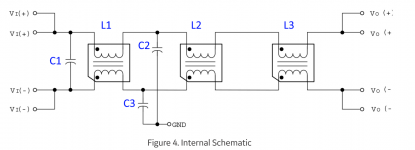
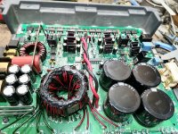
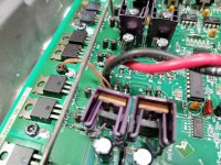
The working principle of Class D inductor:
Inductors are mainly used in the circuit to store energy, filter, oscillate, delay, trap, filter signals, filter noise, stabilize current, and suppress electromagnetic interference.

How to select the right inductor in Class D circuit , for example :
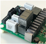
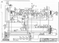
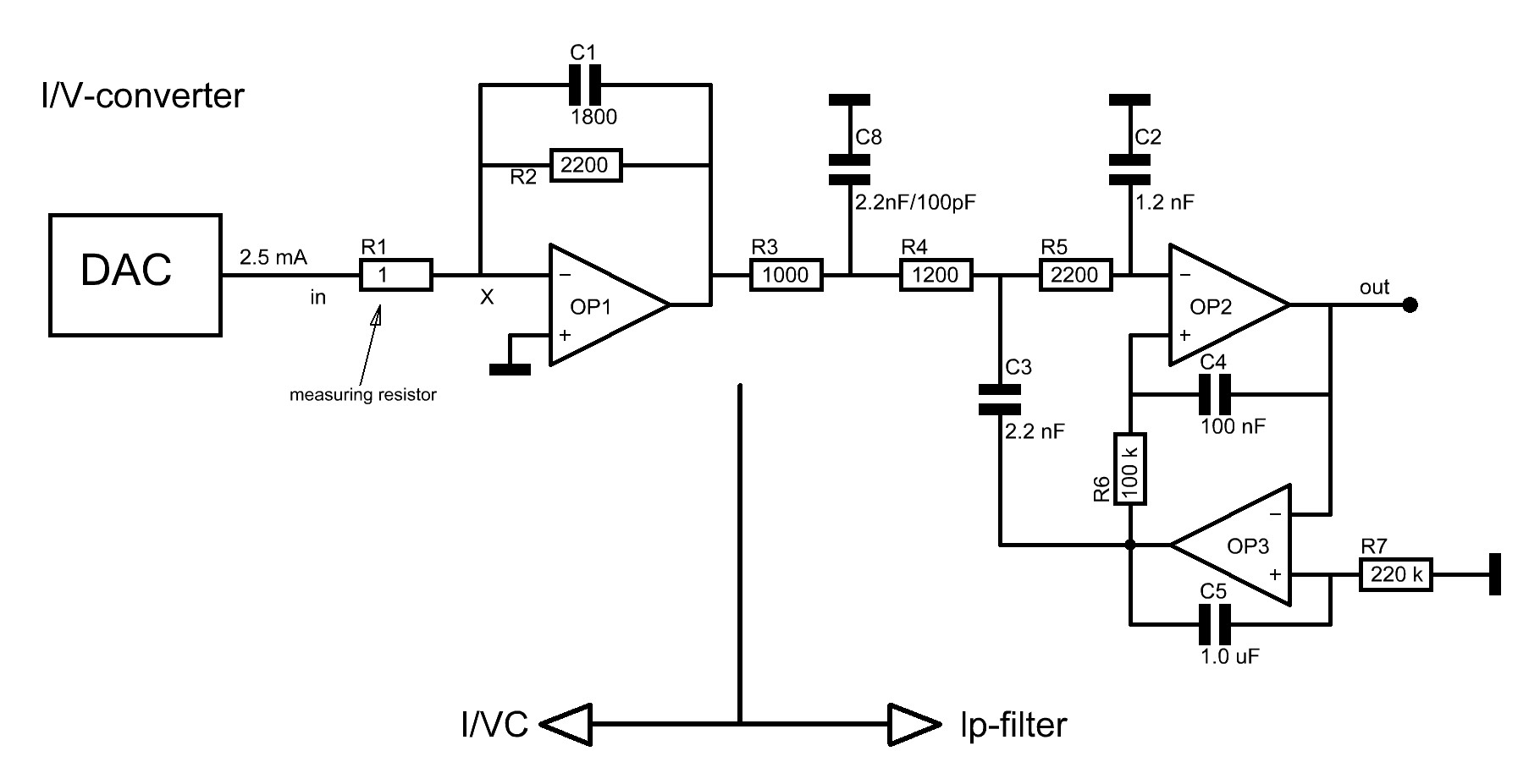
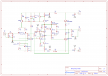
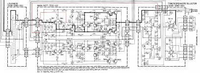
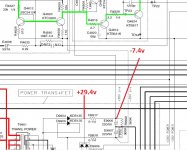
customer sent a schematic diagram of a digital power amplifier, which requires 22uh,2A, power is 25W*4.

Consider from the information already known, what are the inductance 22uh, current 2A, 25W, *4, and what's the qualified inductor?

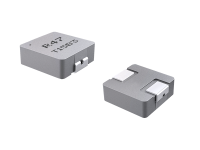
Considering that the power of the power amplifier is not large, the ones that meet the conditions in the impression are selected, SPQ, SPRH, one-piece molding, CSD, CPD, CPE, and these series can be done. From the consideration of cost performance, the CPD and CPE series are screened out. It is a big cow pulling a trolley. In terms of quality priority, the SPQ series screen is removed, and then the CSD screen is removed from the consideration of cost performance. Finally, SPRH is left, and two series are integrated. From the quality and durability, the company’s main recommendation is to select and recommend the use of integrated inductors. , The customer output current is 2A, then the recommended rated current needs to be greater than 2*1.3A=2.6A, and the qualified inductors are CSAB0740-220M, 2.8A,CSAB1040-220M,5A
Customer does not limitation of the size, so It is recommended to choose CSAB1040-220M with a large margin of electrical parameters.

Busk/boost: 1. Suitable for the application frequency of the magnetic core material.
2. The overcurrent of the inductor is 1.3 times greater than the peak current.
3. The overvoltage of the inductor is lower than DC48V.

Half-bridge/full-bridge/PFC inductors:
1. Suitable for the application frequency of the magnetic core material.
2. The overcurrent of the inductor is 1.3 times greater than the peak current.
3. The overvoltage of the inductor is higher than DC300V.

Comparison of magnetic loss of various magnetic materials:
1. Iron powder core 800mw/100K
2. Nickel iron 260mw/100K
3. Mn-Zn 230mw/100K
4. Sendust 200mw/100K
5.Iron-nickel-molybdenum 120mw/100K


https://codaca.com/en/search2.html?m=home&c=Search&a=lists2&keywords=CSAB1040&lang=en#pos

Attachments

  • CODACA class D.png
    CODACA class D.png
    111 KB · Views: 161
  • CPD2315B-220 AMP.png
    CPD2315B-220 AMP.png
    461.3 KB · Views: 156
  • CSAB1040A.png
    CSAB1040A.png
    98.3 KB · Views: 160
  • Class D circuit.png
    Class D circuit.png
    70.6 KB · Views: 153

Aleph 5 distorsion on frequency over 10KHZ

I have realized a Aleph 5 amplifier but i have a problem:

With a resistive load of 8 ohm and input sinusoidal signal i see with oscilloscope a distorsion near max power over 10 khz frequency, under this frequency the output is good.

The six output mosfet are matched and the voltage across R source is similar

I have regulated current gain near at 50%

The voltage cc with voltmeter across R source of the output mosfet without input signal is near 630 mv ( bias ... ) for every mosfet

The voltage rms with voltmeter across R source of the output mosfet at max power ( before saturation ) is near 430 mv / 460 mv for every mosfet

The current rms through the load at max power is about 2.5 A at 100 hz

The power supply is +/- 31.5 volt

I try to insert photo ....

Laser cut metal folding

Has any member of this forum tried making a chassis using laser cutting to enable the folding process to be made without a press brake or folding machine. As some ventilation is required with most tube amplifier designs it may be possible to design an attractive "flat pack" chassis. I would like to hear from any person that has tried this, it it proves practical we could share DXF laser cutting files on this forum.

Metal Laser Cutting : Fold aluminium and steel sheets easily

Need to Bend Some Metal Parts? Just Do The Wave! - SendCutSend

Rusty Sheet Steel Chair by Max Lamb | Dezeen

Laser cut living hinges for neater designs

120 Volt AC Transformer Two-Pronged Polarized Plug Wiring Question?

NAD C 320 DC-Offset Questions?

So I've just replaced a 230v NAD C-320BEE with a correct NAD 120v transformer.


The wiring of a new two-pronged polarized male plug end is the final step, but I'm not sure that I can just wire the new plug end willy-nilly.


Question:


1.) Does it matter?
2.) If so? How do I determine which one of the two transformer primary mains wiring is the neutral wire versus the 120v hot side.


TIA

Question about a 3-stage LC DC power filter

Hi everyone,

I have been using GE FLTR100V20 75V 20A DC power filters in my class D amps for a while now with great success. They seem to clean up the SMPS noise very well.

I am attaching the internal schematics extracted from the datasheet PDF Access Denied . I also labeled the components in the attached schematics (C1-C3, L1-L3).

What values for the inductors (L1-L3) and the capacitors (C1-C3) would you guys use if you had to implement this DC power filter on a prototype breadboard? Also, how would you improve it?

P.S. To be frank, I expected to see at least a couple of non-polar film/ceramic capacitors in there, but it appears that they are only using polar electrolytic capacitors.

Attachments

  • FLTR100V20.png
    FLTR100V20.png
    59.2 KB · Views: 270

LX 521.4 - Anyone complete sets in SoCal area?

Pardon me for creating a mint-new account for this, but I'm not much of a forum user. I think I'm in the right place with this particular request, however.

I have purchased construction plans for the late Linkwitz's flagship speaker design, the LX521.4. I'm sure many of you know about this speaker, or indeed may know someone who has built a set for themselves. I would like to build one, but the expense for me is quite steep, so I would like to try before I buy, in a sense.

Might any owners of this speaker be willing to share the fruits of their labor with me, and indulge me in a demo? I am in Los Angeles and looking preferably for someone close to me, even more preferably for someone with a turntable capable of playback through the speakers. If I can't find such a right person within proximity, I would be willing to make a little trip out to you. I can offer you money or a vinyl record in exchange for your time, and would abide by whatever COVID protocols you think necessary (within reason); I am vaccinated. I can email you a scan of my driver's license to ensure safety.

It used to be that one could go to Mr. Linkwitz's home and demo his personal set of speakers, but no more, for obvious reasons. For better or worse, this makes y'all who have built these speakers their new ambassadors, and I hope I can meet one or several of you soon.

Limiting short-circuit current for 230V testing supply

hello,

I plan to make an AC testing supply for the bench. Idea is to have some tools in a box :
- line filter,
- galvanic isolation,
- switch neutral to earth
- differential switch
- power/volt meter
- variable or step limiting fuse
- variable voltage not requested but if possible

there are tons of solutions ! At first sight, a Shaffner two stages filter, an isolation transformer with screen, a combi power volt meter and a differential switch on DIN rail... for variable short-circuit may be a selector with differents automatic thermal fuses....

Tell me please if you have another way to answer the need.

Have a nice day.

How to fix front panel door on HK AVR 435

How to fix front panel door on HK AVR 435 (solved)

1) I have a used but fully functioning HK AVR 435 home theater receiver. Works well but the bottom panel door does not close, parts are plastic but am wondering if there maybe a way to repair (diy of course). Thin magnet glued to the door and panel work?, velcro likely will leave a gap.

2) On the same receiver volume knob silver color has several spots that has peeled off. where can I expect to find a touch up paint that may work?, home depot or car parts store?

Attachments

  • 2021-07-12-094034.jpg
    2021-07-12-094034.jpg
    118.2 KB · Views: 110
  • 2021-07-12-094009.jpg
    2021-07-12-094009.jpg
    169.7 KB · Views: 114
  • 2021-07-12-094020.jpg
    2021-07-12-094020.jpg
    177.9 KB · Views: 108
  • 2021-07-12-094052.jpg
    2021-07-12-094052.jpg
    138.7 KB · Views: 113
  • 2021-07-12-094106.jpg
    2021-07-12-094106.jpg
    153.9 KB · Views: 119

Recommend kit for 2-way active (home theater)

I'm looking to do a 2-way with active crossover (MiniDSP). They'll get paired with a SVS PB-16 Ultra sub. I'd like to just keep it cheap - let's just say, under $300 for the pair. Should be do-able, I'd think, since no crossovers are getting built.

I know (well, from research, anyway) that 2-ways aren't ideal for this, and there are limitations. So let's just see how well we can do, inside the limitations.

I'm not that knowledgeable, so please be gentle...

DAC Output Stage using AD812

Hi folks

I want to build an output stage for current output DACs such as the PCM61 so I have been looking at I-V conversion methods.

Rather than use the op-amp built into the PCM61 it is better to use an external opamp with better specs. The op-amp inside the PCM61 DAC chip has a slew rate of only 12V/uSec but to properly reproduce the signal coming out of the DAC the opamp should have a slew rate of 1000V/uSec.

The AD811 has been widely used for I-V conversion and has a slew rate of 2500V/uSec. I don't have any of those and they are expensive, but I do have several AD812s, which is the dual version and has a slew rate of 1600V/uSec.

The PCM61 also requires the external opamp to have close to zero input impedance, which the AD811 offers.

Anyways, after research I found lots of people had successfully used the AD811 with the PCM61 or one of the similar Burr-Brown DACs.


I don't see any reason why I can't substitute the AD812, but I haven't been able to find any circuit schematics specifically for the AD811/2 as an I-V converter.

So does anyone have a suitable schematic for an I-V converter using the AD811/2, or can I just use something like the scheme present by Herbert Rutgers:

https://www.by-rutgers.nl/IV-converter.html

IVconverter.JPG

Teflon Tape Plugs

I recently experimented with wrapping the inside of my RCA connector with a regular white PTFE/Teflon tape that are usually used in plumbing. After a bit of listening, I found a bit difference in the wrapped vs the unwrapped connector. It sounded more defined, and more clearer than the unwrapped connector which is a bit veiled.

From what I understand, PTFE is one of the best dielectric material, but air is the best. My question is, in theory the unwrapped connector should be better because it uses air as a dielectric vs the teflon wrap. Why does this happen? Thanks!

Looking for used Mark Levinson 332 voltage gain board

I adopted a ML332 that has some technical issues. The usual failures such as bad main caps are present. There is also evidence of some rather shady repair work on the right channel voltage gain board. Long story short that board has had a major failure and some traces on the edge of the board were disintegrated. Whoever attempted the repair did some real shady point to point soldering with un-insulated tinned wire. They also removed a chunk of the burned area with what appears to be needle nose pliers. Now there is a small jagged chunk of board missing. Not cool at all. The person who did this should be tarred and feathered.

So I am in the market for a replacement board. I am not concerned with the working condition of the replacement. I just would like a nice board to start with and I will troubleshoot the rest later.

Anyone know where I can get my hands on a scavenged board for ML332 right channel? Thanks!

mg12 crossover

hi, unfortunately my room dictates both speaker and listening positions. I am getting a ~10bd spike at frequencies 120hz down to 60hz. would a notch filter (image attached) work to attenuate this?
I think it would bu I'm looking at about £100 in part to find out, which isn't a problem if it works.

cheers adie

Attachments

  • Screenshot_20200629-224720_Chrome.jpg
    Screenshot_20200629-224720_Chrome.jpg
    114 KB · Views: 176

A song you cant get out of your head

Been a DJ for 40 years and always been heavily into music.
Songs come and go and seem to be addictive for a while.
I recently did a search on youtube for older songs that might be good.
I found a Deep purple track from many years ago and just need to keep listening to it. Its not as repetitive as most songs.
A slow starter but is very good.
Which song can you not get out of your head ?
Deep Purple - Knocking At Your Back Door (Perfect Strangers) - YouTube

The Intellectual People Podcast - Dan Wright of ModWright Instruments

Dan Wright started ModWright Instruments as a hobby to modify equipment. Today, ModWright has grown into a well respected Audio Company which leverages Dan's design skills along with some of the industry leading circuit designers. Please enjoy Dan's story as it's quite an interesting one!

Dan Wright of ModWright Instruments | Ep 34 - YouTube

Attachments

  • Modwright Thumbnail.jpg
    Modwright Thumbnail.jpg
    110.4 KB · Views: 95

IRS2092/IRFP4227 Output DC problem

Hello
I have 2ch class D DIY apm. Iraudamp7 conception. The first is fine, the second has a problem. The sound is good but 0,8 - 1V DC at the output (not signal). The DC voltage increases with the load and the external DC protection switches off. I replaced the transistors, but that didn't help. May be IRS2092 defective? What else can I check?
Thank you for any help.

Rudimentary thermal tracking solution for to92 transistors

For my modular preamp im working on a grandious version of a diamond buffer with cascoded current mirrors- 4 transistors per mirror, and only with to92 transistors. In trying to tweak the most out of the circuit by implementing a thermal tracking, i had an idea thats probably more doable then looking for an unobtanium to92 heatsinks.

What if, a flat headed to92s were used (such as zetex brand ones) and and they lined up single row front to back and then bam, tied all up with shrink wrap? Im not good enough to do the layout in my head but i imagine the traces will be suboptimally long. But still this simple solution of thermal tracking is hard to ignore.

What do you guys think?

Size box for my Dali Phantom 7" with limited specs.

Hi all this is my first post I spent all last week making some speakers and have just uncovered these Dali Phantom 7" woofers I had in storage. I'd love to use these In conjunction with with my new 6.5"SB acoustics SB17NRXC35-8 speakers (will separate the Dali 7" and SB 6.5" with divider in speaker box to simplify my calculations)

Problem is there are no specification sheet for the Dali 7" woofer on the internet which makes it near impossible for a novice like me to try and incorporate them my DIY ported cabinets. I have a spare 50 litres available space in each cabinet for them and was thinking I'd only need 20 or 30 litres of that for a Dali 7"

The only info I have is the Dali 7" were used in M-375 in wall speakers with two passive radiators. Here is the cutout size of it
29.6" x 8.9" x 3.9"

The inside cone volume which I measure this morning is 350 ml equals 360 cubic cm volume. The 2 passive radiators in each enclosure should measure the same which comes to 720 cubic cm which converts to same for port volume.

Is anyone able to close approximate what size port and enclosure I need. I'm thinking 20 to 25 litres and a port size 6.3 x 23 cm. But this is only a rough guess based on rudimentary calculations any help appreciated.
Regards Tim

IMG_20210714_072243_031.jpg

Screenshot_2021-07-14-05-59-48-793.jpeg

How to evaluate diminishing returns?

When producing open source designs, or engineering designs in general, one would like to compromise between good performance and that which can be built within the budget and skill set of one reasonably skilled. So the question I ask myself is: how do I know if a level of performance can be not be so difficult to achieve in practice as to be practically unattainable, and if the level of performance is going to be perceptible or provide value to the consumer?


Now this may be heresy to ask this question on a forum dedicated to achieving the highest levels of audio perfection, but it is good for such evaluations to exist so that designs can be out there that can provide satisfactory or even excellent performance without extreme expense or difficulty.


As a wise old engineer once said: anyone can design a bridge to stand up, but only a good civil engineer can design a bridge to barely stand up.


After doing some searching out on the net, I was trying to find how much information there is on perceptible maximum permissible THD or other measures of distortion or noise (odd or even harmonics), amplifier slew rates, perceptibility of distortion in loud signals (sine wave or music), how well speakers can reproduce sound from voltage source inputs and current source inputs, what effect does speaker resonance have on audio perception, etc.


I realize there are probably very few objective ways to answer such questions, perhaps using psychophysical tests, for example A/B testing, and a lot of the audio business is marketing. Still, there are quantifiable measures of system performance, its just that it may not be that well understood how those measures relate to perceptual differences.


Is there some kind of compilation of research or bibliography of such research? How do other engineers go about obtaining answers to these questions? I would like to build a bridge that perhaps stands up perhaps more than BARELY but not for a hundred times the required load either.

How long befre the Pot is passed switch cleaner ? ?

I was at a house clearance place I visit every friday and saw this .. liked it and bought untested for £20. It I know it needs an new stylus but it does play records .. auto drop works etc.

mihRJ2D.jpg


fmev7Bn.jpg

BdaxFuO.jpg

Mhj6zIO.jpg

After a nice soak with Servisol Super 10 the hum and crackle on the volume pot has gone. The left speaker sounds great but I think the balance pot is beyond saving. As you see it 75% over to the right before I get balance and the right speaker is a bit muffled but not bad.
It could be speaker, it may be going. If I turn the balance all the way to the right and crank up the power its loud.
But the balance pot is loose.
I'm thinking I need to replace it, what do the tech's think?

Crossing over a tweeter to a full range driver at 6 DB?

Good morning everyone..I had no idea were to post this topic but, here? I am looking at putting a capacitor on a tweeter at 6 DB on my speakers with a full range driver. I keep reading that the calculators online really don't know what they're doing and they can do the crossover wrong because you're not measuring them or measuring the drivers? I have a few programs I paid for that I can use..The driver am using is full range but, I want it not just for cosmetic looks but also for little bit of Sparkle On Top. Please let me what you think? Jeff

Topping D30

Hello,

I have an old modified CD player REGA Planet and i have bought an second hand DAC to connect digital gadgets to my rega amp and my totem arro.
Wen i connect the DAC, i notice some lack of Mids , its define and clinical but doesn't give me natural sound has the CD player DAC.
The Topping D30 have an OPA2134, what is you suggestions?
I have seen some reviews OPA627,OPA1622, MUSES8920,SOUND OPAMP V5i , MUSES02.


Or it will be better to throw away the topping.

thank you

req. suggestions for re-purpose / salvage damaged LCD TV

Hello,

My 32 inch LCD TV's screen/panel got damaged and its not showing up picture well. Service guy told its not reparable and only option is to replace the LCD panel, with its cost and panel availability in question, its better to go for new TV.

Is there anything interesting we may make out of this TV, re-purpose or salvage any parts in it to make something useful.
We may get couple of speakers, but again it will be difficult to plan for a box for them without its specifications (ts parameters).

While looking in youtube/internet only thing i found so far is to re-purpose it as a big bright lamp, which is not much interesting or worth with the size of lamp we will be getting.
Is there any thing else we can do with it.

Diy bench power supply snag help

I built this power supply years ago. Its 0-50V and 0-4Amp.
Its been serving me well.
I recently built a mosfet amplifier and decided to test it with my dual bench power supply.
I connected an 8ohm load and 1khz input signal to the amp, and powered it up.
Works great until i reach a certain output level. Then my bench supplies start dropping the voltage and my current limit drops down to 2 Amps from 4 amps.
I did notice that if I bypass the current sense resistor R8 with a piece of wire, the current shoots back up and I regain my full 50v output.
This tells me that there is an issue with the current limit circuit.
I can see a slight oscillation equal to the 1khz fed into the power amp input on the supply rails of my power supply.
I suspect that this is feeding into my current control circuit.
Is there a way to fix this on my circuit??. See attached.
I know its not a fault on my amp board as it powers and works fine on a commercially bought power supply.
Thank you!!

Attachments

  • 55284FBE-F8C7-4ACE-BDD6-9340804ED5AC.jpeg
    55284FBE-F8C7-4ACE-BDD6-9340804ED5AC.jpeg
    879.9 KB · Views: 210

8 channel audio, no idea where to start

Hey!

I am trying to get a low cost solution to play 8 independent audio streams over speakers.

I have been looking at the Octo Audio for the Rasp Pi, but I am mystified at how it works...

The idea I am working towards is having 8 speakers playing different .wav files (or 1 wav file with 8 channels). The 8 channels are going to have different delays built into them so they are being played at different times.

From an audio processing standpoint the way I understand it is:
1. There is the Pi audio processing that gets the signal to the RCA outputs.
2. The signal then gets sent to the speakers and it plays the music.

I think I have been able to read up on #1 and think I can get the audio sent to the RCA outputs, but I am not sure I understand #2.

I am really struggling to understand how much power I can deliver to 8 small speakers. Do I need to put inline amplifiers to each speaker?

Is there a better way to cheaply deliver 8 unique channels to 8 unique speakers?

Soldering Iron/Station

I'm in the market for a new soldering iron. Something for doing simple crossover work and possibly some diy amp building and repair work in the near future.
The iron I have was a hand-me-down Weller WTCPN, I believe it's an early 80's unit that's seen better days. I'm looking for something a little more ergonomical.
I've set my budget around $150 USD or so. Models I've considered are the Hakko FX888D, Weller WE1010, KSGER T12, and the TS100, TS80P type irons. I'm also open to other suggestions as well.

6h30n-dr tube tester

Hi, I'm checking some 6h30n-dr valves of my bat vk51se preamplifier with an EICO MODEL628 tube tester with the specifications of the 6922 valve and they all give me good in the area of more than 80 life, but when I put them in it makes me noise when lowering and raise the volume or mute or change fonts.
I've bought macheted sovtek valves and they don't make any noise, but the sound isn't as good as the DRs.
Would there be some way to find out which valves are wrong with the EICO tube tester or in some other way.

Transformer supply for Tentlabs filament supply

Hi. I'm looking at buying the Tentlabs filament supply for my amp project. The Tentlabs website says that each unit should have a separate transformer secondary though. My current PT only has one available 6.3V winding, but it's rated for 5A. Is there any reason I can't connect both units to this in parallel?

As an alternative, I also have a spare transformer with a centre tapped 12.6V secondary. Is it possible to use the centre tap to make this behave like two 6.3V secondaries?

vintage kenwood amp help

Hello, i have a friend that gave me an old kenwood kr 3400 from the 70´s. i liked the sound and since is a simple to get the main boards out and i had caps at home, i made a recap on the power supply and on the main board after i dowloaded the schematic.
When i looked at the schematic i found the the bass and treble controls are connected to the negative feedback of the amp. i´m trying to find a way to disconnet them to bypass the tone control pots but i need some help.
I don´t know if i took off the first input 6.8uf cap and the 6.8uf output cap from the tone controls block will to the trick.
i tried only disconnect the negative feedback pin 5 and 6 on the main amp and i have more gain and also litle noise mixed with music.
the ideia is to bypass the tone controls and maintaining the amp linear.
thanks.

Attachments

  • kenwoodkr_3400.jpg
    kenwoodkr_3400.jpg
    1.1 MB · Views: 416

Adjustable Cathode Bias with TL431

I just want to share a mod of cathode bias, that I have good results on my Dynaco SCA-35. It will be equivalent to "fixed bias" without the need of negative power rail.

You need one this mod for each single tube, so that you can adjust bias point of each single tube.

Q1 needs to be medium power transistor such as DB140 to dissipate the heat.

Attachments

  • sch.PNG
    sch.PNG
    17.7 KB · Views: 408

Fane 12-250TC vs FC152 (15-300TC)

Hello.

I just made some boxes for the Fane 12-250TC, and after running some sweeps and hooking up a regular minidsp 2x4, tried running them in a bit and do some listening to see what's the difference between these things.

The room I tried the 12"s in had some issues, but after applying 6 bands of EQ I was able to get fairly even response, and while remaining within limits of power supply, amps, minidsp and the drivers themselves, I get nice even response and can play around 105db from low-ish bass region and up at ca 1.5 meters.

The boxes are about 120liter BR/TL pending on definition, I applied a 35hz 48db/oct BW HP filter to keep the drivers safe.
I put some melamine foam and metal grilles in front of the drivers. I will probably ponder a bit the amount and placement of foam, as I feel there are some minor improvements to be made.

Here is a sweep using a somewhat agressive "house curve" (that I actually decided to remove afterwards, no measurements sans "house curve" sorry!), sweeps are roughly 0-10-25-40 degrees in a rather noisy enviroment (close to road).

Sounds great, a tiny bit hot at 0degrees like the 15", so far I prefer the 15" overall, tiny difference.

Will be back with more later on. Maybe more measurements in a week.

Attachments

  • minidsp 12-250TC.jpg
    minidsp 12-250TC.jpg
    208.9 KB · Views: 978
  • Measurements Fane 12-250TC after eq.jpg
    Measurements Fane 12-250TC after eq.jpg
    222.9 KB · Views: 990

Variac buying advice needed, safety concerns

I've been thinking about buying a variac for servicing tube amps.

I live in Finland where we have 230V line voltage. I've been looking at these devices on german ebay. My main concern is safety.

What do you think about this one?

s-l400.jpg


Those screw in banana terminals look quite scary to me. OTOH the device is in a neat looking box. Some other ones seem to have like a US type wall socket. That doesn't help much here in the EU.

Here are some of the options if anyone is interested:
variac | eBay

Rockford Fosgate Power BD1000.1 issues

Rockford Fosgate Power BD1000.1 - works, produces sound but...

There is something like a switching noise at the output speaker terminals (can be heard really well even with a subwoofer mounted in the trunk).

Another concern is Q13, Q14, Q15 and Q16 are getting extremely hot in a very short time. Is that an indication of an issue or it is "factory" like that ? I can replace the heatsinks and use a bigger ones but that would not resolve anything if there is an actual issue.

Any guides ?

Attachments

  • rockford3.jpg
    rockford3.jpg
    131.8 KB · Views: 110
  • rockford2.jpg
    rockford2.jpg
    177.7 KB · Views: 111
  • rockford1.jpg
    rockford1.jpg
    135.1 KB · Views: 100

FS: Ortofon SPU (AlNiCo, Line Contact)

Hello,

I need to downsize my collection therefore I am selling my Ortofon SPU (ALNICO magnet) nude, but I am selling it with an adapter to make it usable in standard headshells.

Specifications
Tracking force: 20mN
Tracking ability: 90 micron/20mN/315Hz lateral
Stylus: Line Contact III
Cantilever: boron
Coils: copper (original)
Coil impedance: 1,9 Ohms/ch DC
Damper: new (silicone)

After the rebuild it has been barely used (less than 5 hours) and the cartridge has just been checked and cleaned by Ana Migthy Sound before the sale to ensure that the new owner will have a trouble-free playback.

Asking price: EUR 800 plus shipping

Snw6Y0e.jpg

2QOY3yP.jpg

6Ha151N.jpg

JnEIVR6.jpg

pZYDPI7.jpg

PQ346Vy.jpg

NLwQkKj.jpg

FS:DCB1 Salas built with top components

Unit works perfectly although some refinement work need to be done for aligning better both the volume control and the switches. Rotating the control is not perfect as there is a slight misalignment between the switches rods and the Elma selector and volume attenuator. the attenuator works smoothly but the selector switch has some noise. I bough this for a fellow one year ago and he planned to re-case it in a new chassis. I bought it as is and due to transport issues I had to replace the 4 fast recovery diodes and with all the tight tolerances I could only reposition one of the cooling heatsink at 45 degrees. As said you can use the unit as it sounds perfectly but if you are a perfectionist you will not tolerate this. This is a 650mA unit
List of components:
Acoustic dimension attenuator, 41 steps (only this costs 150 Eur)
Elna selector
Jupiter Cu foil and wax coupling caps
Riken ohm and shinkoh
silver wiring
4 Inputs and 2 outputs
100Va trafo.

Will sell without the chassis bottom cones as too expensive and what to keep them.

Chassis is basic as you can see as the plane was to rehouse it., I put two stickers on front panel to make it nicer, they comes from my modular electronic activities.

Ship in Europe only and beware UK buyer will have probably to pay duties due to Brexit.
Toroid wired for 230 Volts.
Price 400 obo, shipping included
Paypal is fine

Revox B226 issues

I have a Revox B226 with issues. It powers up, the tray operates smoothly and the CD starts to load. The spindles starts up and spins for a few seconds, no track info displays and then the spindle stops. I have read a few threads here and started to pursue some of the suggestions. So far I have downloaded the service manual and schematics and cleaned/inspected the inside of the unit.

I plan to clean the laser, check the adjustment of the torx screw under the motor and check the condition of the electrolytic caps. I started by trying to inspect the 5 electrolytics that are supposed to be on the drive board under the unit. I found that my drive board does not have 5 EL caps and the board says Studer instead of Revox. I have included some pictures. Can someone tell me which transport I have and if this unit has been previously repaired or did they commonly mix circuit boards between Revox and Studer markings? Also, how do you suggest that I proceed? I have a scope and good electronics knowledge but this is my first CD player repair.

Thanks,

George

Attachments

  • B226 front.JPG
    B226 front.JPG
    214.7 KB · Views: 498
  • B226 rear.JPG
    B226 rear.JPG
    258.3 KB · Views: 445
  • B226 plate.JPG
    B226 plate.JPG
    472.8 KB · Views: 557
  • B226 board 1.JPG
    B226 board 1.JPG
    532.5 KB · Views: 530
  • B226 board 2.JPG
    B226 board 2.JPG
    850.1 KB · Views: 707
  • Transport.JPG
    Transport.JPG
    805.6 KB · Views: 510
  • B226 transport.JPG
    B226 transport.JPG
    388.9 KB · Views: 458

Which 10" driver for 4m TL?

Hey Guys,

I'm planning to build my first sub and it will be TL of around 4m length. 😀
My goal is to add the really low frequencies to my audio system: like down to around 15 Hz. I'm not looking for extreme SPL (I have neighbors), but quality sound.
I have a corner in my room to fit a tower shape of around 30 cm width and 30 cm depth, 240 cm tall. Because of the width, a 10" will be the max size.
Within the 240 cm I can easily make a very long TL with just 1 fold.

First try in Hornresp with a Seas 10" on 125 Watts:

attachment.php


First question is: which driver should I take?
I think I have 2 reasonable options I can afford:
SEAS XM001-04_L26ROY for E 250,=
Dayton Audio UM10-22 for E 230,=
What do guys think of these? Any experiences?

I think about a Crown XLS 1002 to amp it. Enough power (1100 Watt bridged on 4 Ohm) and a very usefull adjustable lowpass filter. So I won't need to build a passive crossover in my sub.

Attachments

  • TL-sim.png
    TL-sim.png
    68.6 KB · Views: 1,410

Alpine PMX-F640 pre-drive issues

Hi mates

Alpine PMX-F640 stays in protect.
Defeating the protection circuit turns on the PS section, but there is -7v DC offset on all of the speaker terminals even without the output BJTs.

Found something in the pre drive circuit is not OK, picture attached. Instead of +30v at the + line there is -7.4v dc. Any help would be appreciated to fasten the process to find the issue.

Schematic is in the attached file.

Attachments

Which order to apply room correction tools?

I am now at the point where I want to try some equalization, timing, etc. My system is 2.1 with 3 subwoofers. My DAC/preamp is a MiniDSP SHD, so I can do all of the DSP filtering these tools offer. It also includes DIRAC. What is the best sequence to apply these tools: e.g. B, A, D, C, etc.?

A. Front Speaker placement, with help from "Rational Speaker Placement" (Sumiko Method)
B. Multi-Sub Optimizer (MSO)
C. DIRAC
D. Sub placement - crawl method or ??
E. REW - frequency response filtering
F. REW - timing and phase adjustments
G. Room treatment

Thanks

Sunfire HRS-8 resistor identification

Im working on a Sunfire HRS-8 that suddenly decided to stop working. No power or standby light. Its not the usual humming, pops, etc that affects many Sunfire subs. Pulled the plate amp and everything seems normal accept there are afew SMD resistors on the standby board (one in paticular that looks charred). I cannot read the resistance and was hoping someone might be able to sneak a peak at their amp if they have one available. The resistors in question are R438 and R439 on the standby board...R439 appears to be the worst shape. This would be sooo much easier if carver would just publish the schematics. Pictures attached. Thanks

Attachments

  • IMG_6273.jpg
    IMG_6273.jpg
    765 KB · Views: 176
  • IMG_6274.jpg
    IMG_6274.jpg
    985 KB · Views: 173

Lm7809 hiss noise

Hi, i am building regulated power supply for guitar effect (compressor).

There is a bridge rectifier (db107) and a cap (4700uF).
The regulator has 220nF at input anf 100nf at output.

There is no hum, but a sibstantial hiss when I run the effect. Putting another 4700 uF at the regulator output reduces the hiss, but still something remains.

There is no hiss if I power the effect with a 9v battery.
Changed the electrolytic caps, but hiss remains.
What could be wrong?

Can I reduce noise further, if cascade 7812 and 7809 in series? (7812 feeding 7809)

Regards

  • Poll Poll
PCBONLINE Aluminum Nitride PCB One Stop Manuacturing

Typical Applications of aluminum nitride PCBs?

  • IGBT module

    Votes: 0 0.0%
  • VCSEL module

    Votes: 0 0.0%
  • CPV (focused photovoltaic) solar power supply module

    Votes: 0 0.0%
  • High-power LED lighting

    Votes: 0 0.0%

News:

Do you want one-stop aluminum nitride PCBs for LEDs, solar battery modules, car-class IGBT modules, aerospace, defense, medical...? PCBONLINE provides 100% aluminum nitride PCBs. PCBONLINE is a competent partner for ceramic PCB solutions because of:

  • PCBONLINE adopts DPC technology that can achieve three-dimensional design;
  • A better welding performance and more high-temperature resistance;
  • Arbitrarily customized circuit layer thickness between 1μm-1mm;
  • Has high-density process capability - 20μm minimum line space;
  • Free one-on-one engineering support (DFX);
  • Online register, instant quote, $100 coupons for online purchases.

Email: info@pcbonline.com
Visit our website: PCBONLINE Official: Middle and High-end PCB Manufacturing and Assembly

very low wattage power stage question

Hi all,

I have been searching the forum for wisdom on designing an output stage that does not favor maximizing wattage, but understandably there are many more threads dedicating to squeezing the most out of each tube. Several years ago I built an Aikido preamp with 6sn7s and provided them with a generous PS. I wondered the other day if I could use that unused B+ to supply an unimposing pair of output tubes. The transformer HV secondary is rated for 150mA and the 4 preamp tubes use around 40mA all together. Would it be possible or advised to fit a pair of, say, 6l6s in there so they draw no more than 40mA each and still sound good? The Aikido provides a lot of voltage gain, I have efficient speakers, and I plan to listen at modest volumes near by. I love the idea of adding an output stage for the price of 2 tubes, OPTs, and a handful of small components. Am I dreaming? If not, what tubes should I consider, and are there any simple schematics that lend themselves to this objective?

Thanks for your suggestions.

Passdiy Pearl 2 Phono stage

Built it late last year. I guess not much description is needed here. I used the same enclosures 6L6 used in the build thread, but silver in color. Umbilical with XLR connectors using Kimber wire. power supply using the diy audio store PS board.
Inform me if it would be for MC or MM cartridges so the appropriate input parameters are soldered. Would be shipped via USPS priority $700.00 plus shipping.

Attachments

  • 6C737547-6B33-44E7-8D79-307A8CF2526F.jpg
    6C737547-6B33-44E7-8D79-307A8CF2526F.jpg
    914.6 KB · Views: 341
  • 7F4A15E6-7050-4697-BF79-06E926ADF9B2.jpg
    7F4A15E6-7050-4697-BF79-06E926ADF9B2.jpg
    806.8 KB · Views: 230
  • 1719D8B2-8237-4AB9-A4AB-667E5634F441.jpg
    1719D8B2-8237-4AB9-A4AB-667E5634F441.jpg
    705.2 KB · Views: 230

Ross RE-270 Headphones

I was rummaging through some boxes at home and came across a pair of Ross RE-270 headphones I last used maybe 35 or more years ago. I seem to recall they were quite good at the time but needed the right amplifier to do justice to them; otherwise they were not very loud.

Does anyone know what is the input spec for those headphones? Impedance, power, etc.? Are they transformer-inputs? Does anyone have a spec sheet they could scan?

What is the best way to drive them?

Like I say, it's 35, maybe 40 years, since I last used them and had a suitable amp for them. I'm curious to see how they've survived and whether my memory of the sound quality is correct. The amps I now have at home don't have headphone sockets; plugging them into a Samsung tablet, the sound is not loud but seems very clear throughout the frequency range.
Projects by fanatics, for fanatics
Get answers and advice for everyone wanting to learn the art of audio.
Join the Community
507,811
Members
7,889,362
Messages

Filter

Forum Statistics

Threads
406,290
Messages
7,889,362
Members
507,811
Latest member
Cystore