Need enclosure sugestion for Mark Audio CHR 120

Hello,

I never heard a good full range speaker.

I´m from Brazil and here we dont have quality speakers for "home use" because the audio market here only have products for automotive (focused on SPL) or outdoor professional big events

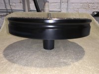
I am thinking in buy from Madisound a pair of Mark Audio CHR 120 because i read that its have a very good bass extension, and it is what i am looking for

and i am in doubt whats enclosure would be the best for my use:

i have a small room 15m2

i hear mainly "old jazz" (miles davis, bill evans, jim hall, dave brubeck etc) and Rock (Beatles, Pink Floyd, Rush etc)

and i want an enclosure that could give the more clear and profound bass i could get from this songs

so from all the enclosure sugestions founded in the Mark Audio site ( CHR-120 | Markaudio )

what will be the one that probably will fit better in my room and in my expectations?


do you think i will be good have a subwoofer to help too?


PS: if there is another speaker in Mark audio (or other manufacturer) instead of CHR 120 that is better for what i want please let me know too

  • Locked
DIY Sony VFET lottery entry

This is it 🙂

This thread will remain locked until the first lottery entry window opens.

----------------------------------------
How to enter:

  1. Read the VFET Store Information Page
  2. Please go to diyaudio.com/vfet before the window opens
  3. You will be automatically redirected to the right thread 1-6 minutes after the lottery opens, to help spread server load. Please wait to be redirected. Thank you for your compassion!
  4. Post one short and sweet message ("In!" is fine...). Please wait until the window closes before making another post in the forum.

We're taking a "Hope for the best, plan for the worst" approach. We'll be monitoring the server and if it has any issues, the event will be extended until there's a full 15 minutes without issues. Additionally, if our database connection limit is hit (which prevents the server from overloading), you'll be provided an off-site link to enter.

----------------------------------------
Further reading and discussion:

OUTPUT TUBES ON HK TA5000X

Right now my receiver is working pretty good but seems a little under-powered and is not incredible balanced channel to channel. I have a mismatched bunch of old untested 7355 power tubes (different brands), which I have balanced as well as the existing circuits allow. Plate dissipation is about 21 watts on Channel A and 19.5 on Channel B, both exceed the 7355 spec'd 18 watts rating. The existing circuits don't allow to lower/raise the bias of the push tube without rising/lowering the bias of the pull tube so all you can do is balance them. Because 7355 are too hard to find, I am going to change the tubes to 5881s, which are pinned out a little different but have very similar specs and 23 watt plate dissipation rating.

My question is this, the 5881 are slightly bigger around and while they fit in place, the clearance between the bottles and the output transformers is only about an 1/8" to 3/16"; the clearance with the 7355s is about 1/4" to 5/16". Is there going to be a heat problem with the output transformer that close to the power tubes ? Should I move them over to get a little more clearance?

Folded horn coax?

Good morning.

I recently found a steal on my local Facebook Marketplace and snagged 4 Eminence Kappa Pro 15 LF2 drivers for less than the cost of a single driver. My grand plans are to turn one into a downward firing sub for my dining room, one is going into a bass guitar cabinet, and for the other two I wanted to do either a 2 or 3 way PA cabinet for my back yard.

Now my rather ambitious design idea was to build a set of folded W horn cabs with a small bass reflex box in the center that holds either a full range driver/horn, or a pro coax driver combo.

So my big question is does anyone know of existing folded W horn cab designs for this driver that I can make some mods to or are able to point me to the right things I need to tune the cab correctly?

some amplifiers for sale: Adcom, ATI, Behringer

Here are some amps I would like to sell from my stash. I will post pics upon request. Payment via PayPal.

All prices do not include shipping. Local pickup welcome near Lansing Michigan.

Adcom GFA-2535: SOLD !


ATI AT1502:
This is one of ATI's first power amps I believe. Very well built and has very solid bass. Rated for 150W into 8R, and you can bridge it for 450W into 8R plus 2dB headroom. I used this to drive some dipole subs for a time, but no longer need it. Cosmetically this is in OK shape, with a few scratches but nothing serious. The LED on the power rocker switch is a bit dim. Otherwise great working condition. I have a pdf copy of the owners manual. Weight is about 40 lbs. I do not have any original packaging but will pack well.
Asking $300


Behringer NX3000 with quiet fan mod:
I have two of these on offer. I replaced the stock fan with a high static pressure, low noise Noctua fan so that they are better for use with home audio. There are dyno tests for these amps online and they have lots of power (although NOT even close to 3kW!). These were originally obtained by me as factory refurbished models, so they were checked over and made as new before I replaced the fan. I never actually used them - I had a project for them that didn't pan out - so I am looking to find them a new home. Both are in good to very good cosmetic shape. I have the original box for one amp, and will pack the other well. They only weigh about 8 lbs!
Asking $250 each.

AR3a "improved" - It works!

If anyone has interest - The AR3a "improved" crossover works.

Please find the schematic and pictures of the finished result at :

www.diagrammer.hobbysider.dk and the AR3a "button".

The AR3a "improved" is ready for playing and sounds great - best with only the specified 1 Ohm serial resistor for the midrange and no reduction of the tweeter signal. Very open sound together with expanded stereo perspective and the well known AR woofer attack.

rgds

Attachments

  • pic_0041.jpg
    pic_0041.jpg
    30.4 KB · Views: 653

JBL 075s Cone midrange horn, unity horn,???

So I have these two JBL 075 Ring Radiator bullet tweeters. At around 106dB/W/m It would take a lot of padding down to mate with normal speakers. So what to do. one could

1. By some really expensive compression driver based mid horns
2. Get a pair of 8 or 10 inch PA midranges per side (or a big line array of 4")
3. Some sort of front loaded horn based on full ranges I have laying around
4. Dive into unity horns using 4" or 6x9" drivers I have on hand.

So 3 and 4 are the most appealing. Can the 075s work firing into the end of a unity horn instead of a compression driver? Anyone ever use 6x9 in either front loaded MR horn or unity horn?

I would be expecting the midranges to cover about 500-5k.

Merging Passive radiator and Woofer nearfield question.

When merging nearfield woofer and nearfield passive radiator, are you looking to match up the bottom ends of the tails like you would with a port merge?

The reason I ask, is I am taking both measurements 1/4" from the cone, but I am having to adjust the PR response up almost 4dB in order to get the tails to match.

First pic, nearfield of woofer and PR, a copy of the PR raised to match the tail of the woofer.

two tails.jpg

Second pic, summation with matching tails.

matching tails.jpg

Third pic, summation with no level matching.

not matching tails.jpg

I know I need to add mass to the PR, but before I start those trials, I would like to make sure I am summing them correctly.

This is to be merged with the farfield of the woofer for use in a two way crossover.

Heatsinking pass transistors in series regulators

Did some searching and didn't come across anything specifically applicable to my situation - happy to take pointers if I missed it!

I've got a couple of pass mosfets in my power supply design that will be dissipating around 7W apiece. They're in a TO-220 package (although I'm open to others), and have a 62.5C/W thermal resistance in free air, so they need to be sinked.

I obviously can't just stick them inside a closed chassis, sinked or not. I see a couple options ... I could mount sinks externally, with a hole cut in the chassis to allow direct contact with the flange. Or I could keep them inside, near an edge, with ventilation holes above and to the side to allow convection. What has worked for you?

Side question - what are y'all's preferred heat sinks for TO-220s? Amazon has a bunch of different inexpensive small sinks, but none of them have any meaningful specifications.

(I've got gobs of heater current to spare, so I've also considered using 6080 pass tubes topside, but that seems unnecessary and expensive.)

Morgan Jones' Balanced Hybrid RIAA Stage

I would like to build a balanced RIAA amplifier capable of an MC cartridge with 0.2 mV output. I have been looking at Allen Wright's RTP amplifiers and Morgan Jones' balanced hybrid RIAA amplifier described in his book "Valve Amplifiers" fourth edition on pages 628-645. I like MJ's design since it is quite well described and draws a lot less power than AW's designs. However, MJ's RIAA stage is designed to give 4 Vrms output with 0.3 mVrms in to match balanced digital sources. I don't use any digital sources and my line stage is designed for 250 mVrms input. Therefore, I would like to reduce the gain.

Ideally, I would like to show the schematic here, but I guess that it would violate the copyright. Hopefully, a few of you have a copy of MJ's book.

The first stage is a cascode with a transistor and an E88CC tube in each leg. MJ writes that the gain can be changed to adjust for imbalance between the channels from the cartridge by adjusting the current in the first stage and gives the following equations:

A = gm * Rl
gm = 35 * Ic

3 mA is passed in each leg of the first stage. If my math is right, I would need to reduce the gain in the first stage with a factor of 10, which would reduce the current to 0.3 mA. Would this be feasible?

I could also reduce the gain by reducing the anode resistors Rl.

Reducing the gain of the second stage is also a possibility.

Can this RIAA amplifier be successfully tweaked to suit my requirements? If so, what would the best way be?

Looking for a very nice dual opamp, for 0 to 48 volt DC power range.

It must be within these parameters:
0 to 48 volt DC ( I can regulate the voltage down using a zener diode).
Maximum 10 milliamperes total current draw.
DIP-8 package.
Minimum self noise. Good common mode noise rejection.

Usage: Amplifier and impedance buffer for piezoelectric elements wired in balance.

Why a impedance buffer is needed:
The problem with piezo guitar pickups and piezoelectric crystals is that they are not well matched to typical audio inputs. By their nature they can generate a lot of signal, but they cannot drive a 50 kilohm typical line input. The pickup needs to work into a much higher impedance, typically 1 megohm or so.

So what to people do? They go and plug a piezoelectric disks output directly into the line input of their recorder, typical impedance 50k, or the plug-in-power mic input of their recorder, typical impedance about 7k, and they start to bitch and moan that this damn thing sounds tinny. Which is does ! But they don't understand why!

The reason why these devices often sound tinny is because the piezo sensor presents its signal through a series capacitance which is small, typically 15nF or less. When wired to a normal 50 kilohm line input this forms a high-pass filter, which eliminates the bass.

Super tweeters

Been wanting to try them for a long time now just to see what the fuss is about and the fact I have two sets of speakers (a 10” two way, and 10” three way) that fall off on the top.

I’ve narrowed down to two sets that would fit the system based on sensitivity, and price (under $400/pr.)

one dipole amt 404 Not Found


– ESS Speakers USA


And a horn Fostex T96A Top Mount Horn Super Tweeter

Yes I know bats, cats, dogs……blah blah, I’m more interested in the harmonics

And also I know YouTube videos aren’t the end all but I’ve seen a couple well recorded comparisons (in/out) when in the transient/focus difference is very apparent.

One cap in series around 1uf or less will get to my target area of 14-16k, attenuation with l-pad if needed.

Just wondering if anyone had any experience with either of these particular units or thoughts on anything comparable.

One thing I’ve been wondering is how super tweeters would effect a mtm, I have all the parts gathered to build a set of 10” mtm but haven’t found time to build yet. Especially interested in the dipole with mtm……it might influence my decision more if it would help fill the vertical gap a little without compromising the narrow vertical directivity that my strange slope/high ceilings are in need of.

Also does anyone have a fr for the ess amt III ? Cant seem to find it anywhere…..they list it as up to 30khz but seems odd they don’t post any graph.

Cant really afford to buy both sets and then sell one so trying to narrow it down.

Thx 🙂

Greetings

Hello all, George here. Just want to introduce myself as a new member. Been interested in vintage audio since before it was vintage audio. I'm sure I will find a lot of interesting information by being a member and hopefully I can contribute some. Cheers

You're gentle." "I, I don't know how I'll do. It's been awhile. And my age.." "Ah, no worries. I saw when you woke up. That first time. Let me try." Now her hand had moved down over my belly. She unbuckled by belt and opened the top of my pants. Her hand slid down further finding my ****, stimulated, but definitely not hard. She began to hold me, letting her hand move along my ****. When her thumb circled the head she said, "Oh you're cut. The men I've known at home weren't. Let me see." Now she slid down, pulling my pants with her. I was trying to relax. livesexchat.cam – live sex chat, live cam sex videos

She touched my face, feeling my salt and pepper beard. Then let her hand slide down to my chest, and down to lay atop my stomach. "I think think you're sexy. And it's cute how you're almost afraid to touch me. A this 20 year old sprite, excited to hold and inspect my currrently unimpressive old ****. She held it up, still soft in her hand, looking me over, pulling and stroking, feeling some response. Then she put my **** in her mouth and began sucking and licking at me. Finally I felt a jolt, my body jump started into the proper mode. Remembering these feelings and the proper response. My **** stiffened a bit. 1freesexchat.com – free sex chat, live sex web cams

"No really. Maybe it's not having family. Someone to look up to." "You should find someone your age." "And where did that get me?" I took her point. Still, certainly she wasn't suggesting... "I've been on my own, Making my own decisions for years now." Now she stood and walked to sit beside me. , her tongue dancing around the head of my ****, she smiled then those same teeth lightly closing on the tip. She paused a moment to say, "See, he's waking up for me." Jeannie began bobbing her head on me, blonde-red hair shining as she sucked and licked. I closed my eyes and tried to let go to the feelings. Letting my mind go blank to any thoughts that could inhibit me. Jeannie was patient and relentless. livesexcams.top – live sex cams, free sex chat, hot girls

Welcome

Good morning,
My name is Tomasz and I'm from Poland, I'm interested in audio equipment and music. I used to build various electronic systems during my school days and for several more years.
After a 20-year break with electronics, I decided to build another amplifier, this time something called Hi-Fi equipment. I have been enjoying music amplified by the FirstWatt F5 clone for 2 months now and I want to go further and improve the parameters of this wonderful amplifier. I bow to Nelson Pass, who, despite sharing the idea, still offers advice here on the forum.
It's a pleasure to welcome all users of this Forum.
Sorry for my English.
Greetings Tomek

Micromega Stage 2 modification - and incorrect info...

Hi,

My first post here. I've been mildly audiophile for many years, and have done minor electronic tweaking (output stages, caps, power supplies) in the past but remain pretty clueless about the digital world.

My system (a few years old...)
-Micromega stage 2 cd player
-Audiolab 8000P+C amps
-PSB stratus silver speakers

The Micromega is either leaving or getting updated. Mine has always worked flawlessly, so I must have been among the lucky few.

Possible updates are:
-Tentlabs or D-clock (www.newclassd.com) clock, with dedicated power supply
-separate power supply for analogue section (transformer, caps and regulators, like the Tentlabs shunt regulator)
-new opamps (NE5534N originally)

Any feedback/suggestions on these? Will it improve the sound, or should I go for an other player? Rather like the sound though...

One possible show stopper: Several references online suggest the stage 2 is equipped with saa7321 converter, which appears to be of rather nice quality. I opened mine, however, and underneath the mother board i found 2x TDA1305T, as I understand a budget DAC found in Cambridge DACMagic and others.

Question remains then, how much further can I go, sonically, with this converter?

Any feedback/hints/suggestions are most appreciated!

Cheers!

Hot-rod bluetooth speaker

Heya.
Just bought and tested Sencor SSS 6800. For the price, it actually does good job. I bought it just for the casing though, to install better components in the platform. Bad move. It is not serviceable, and I ruined it. So much for the easy way.

Now I will start from scratch.

It should be borderline compact and mobile - so not much bigger than the original Sencor. Shape can be round or somewhat boxy, but with small footprint. Sencor delivered that when put on side...

Regarding upgrade, I'm thinking two Daytons ND91-4 and three 4“ passive radiators. Box volume hanging around 3l/0.1 cu.ft.

Did anyone attempt something like that seriously?
Any interesting ideas?
Thanks.

Need Help with an Oscillating Amplifer

Hello All,

I am working on an amplifier with a topology very similar to the simasym amplifier that has been discussed at various times on this forum. The major difference is that this amplifier has a MOSFET output stage and operates at + / - 70V. This is a current commercial design, so I can not publish the complete schematic, but the attachment 1 shows the topology for the VAS and output stages. I blew it up by accidentally powering it up with out connecting the ground to the power supply. I have replaced all damaged components, and the amplifier seems to be in basic working order. The distortion spectrum (attachment 2) confirms that it is operating, but not very well. Attachment 3 shows a DSO photo with a 40 mVrms input, where the yellow trace is the output from the amplifier, and the green trace is that output after a 1 KHz passive notch filter, all looks well. However, attachment 4 shows the same setup but the input was increased to 70 mVrms. The oscillation during the bursts is about 11 MHz. The gate stopper resistors all measure within 2 ohms of the specified value. The propensity to oscillate decreases as the circuit warms up.

I would appreciate any help in directing me toward the source for those oscillation burst.

Thanks in advance for your help.

ceulrich

Attachments

  • Attachment 1.jpg
    Attachment 1.jpg
    30.7 KB · Views: 368
  • Attachment 2.png
    Attachment 2.png
    61.8 KB · Views: 372
  • Attachment 3.png
    Attachment 3.png
    62.6 KB · Views: 347
  • Attachment 4.png
    Attachment 4.png
    41.6 KB · Views: 356

Can I use op-amp with PCM5102A?

Hi, folks
I'll be driving car's head unit through it's CD changer input, so not sure what load is it. Maybe there is a standard for this?
Is it possible to use op-amp with PCM5102A? In my application the load is much lower than 10k, so as a result I have much lower Vrms than it's defined in the datasheet (2.1V). So maybe it's possible to use op-amp or should I use a different DAC chip for this application then?

Anyone have ideas of it? Thank you in advance!

Naim NAP 140 offset voltage

I have just reset the bias current to 4.5 mv across each 0.22 ohm power resistors as per acousta.org advice. Before starting the offset voltage was 7mv each channel. The initial bias was 3mv on channel 1 and practically zero on 2. On completion the offset voltage was rechecked and it had gone mad nearly 0.5 v on ch 1 and 0.2V on the other. All I did in between was set bias and disconnect power supply to measure apprx 35ma. BUT I did not turn off the amp, just pulled out the power tag to the circuit board and inserted the ammeter leads. Then put the tag back. Could this have damged anything, if so what should be checked.
Any guidance appreciated

Mark K's er18dxt

Here Is the design , a basic 2-way monitor using the Seas ER18RNX paper woofer ( same as In zaph's SR71 ) and the Seas 27 DXT tweeter .

The Seas ER18DXT ported two way

It's a rather new design but whats special about it is the Xover network using a second order on the tweeter , makes him play really low ... but it works .

Thing is I was going to build zaph's SR71 until I came upon this , on a meeting of fellow DIY'ers mark brought these things and they were best in show , You can see the link there .

even on zaph's own blog he considers this to be an upgrade from the SR71 , L18 builds ...
costs slightly more then the SR71 ... but probably outperforms it in any way.

your thoughts ? im seriously wondering about building these now 🙂

BC337-40BU

HELP!!

I've been searching for several days for 30 x BC337-40BU transistors. These are the bulk, straight leg type, not the ammo or tape versions which have splayed legs. The best result that I've obtained so far is from Arrow Electronics fro £0.81, plus £32.63 shipping, plus a highly probable £12 Customs charge. Not the best way to buy parts.

I have got some on back order from CPC which were supposed to come back into stock last week. That date has been bumped forward by another month and I anticipate that date changing again. Nobody in the UK and none of my normal American providers (Digikey, Mouser, etc) have stock of the bulk type. They are all giving expected stock dates well into 2022.

Annoyingly, two of my usual suppliers sent me the splayed leg type despite their web pages showing the straight leg types.

I have found several European suppliers who have current stock but they no longer deal with UK individuals due to Brexit (n.b. I voted to stay in!).

Does anyone have these transistors in their stock? Would anyone be willing to order them from one of the European suppliers please? I would of course cover any reasonable costs incurred.

OPS asymmetry

I am modeling an amplifier with Multisim using an EF3 OPS with 6 pairs of MJL3281A/MJL1302A driven by MJE15032/MJE15033.
With a 1KHz input signal and an output voltage of 34.6VRMS into a 4 ohm load (300WRMS), the Fourier analysis of the output node shows a THD of less than 0.0001% (9 harmonics) so the closed loop behavior seems OK.

I do a Fourier analysis of the VAS (the test node is the connection of the VAS collector to the bias spreader) to get an idea of the "correction" applied to the OPS.

With 0.2R emitter resistors, the VAS THD is 0.054% with a dominant 2nd harmonic (0.026%).

Changing the emitter resistors *only* on the PNP output devices (MJL1032A) to 0.26R (empirically determined) lowers the VAS THD substantially to 0.011%, now with a very low second harmonic. (<0.0002% = much better symmetry)

The bias is set for best THD (approx. 70mA).

I thought that something may be wrong with the models but I also tried MJL21194/MJL21193 with similar results.
Looking at the data sheets, I see that these PNP devices tend to have a higher current gain which seems to explain this.

Your thoughts and/or experiences please.

[POWER AMP] Hypex NC502MP full balanced 2x350W / 8R, free shipment Europe

Hi,

I selll a brand new Power amp based on the Hypex NC502MP module.
Everything is mounted with a great care
2x350/ 8 ohms
Full balanced inputs + Audio grade Filter module
Push Banana Plugs
Full alu case

Paypal Only
Free shipment to Europe only please.


Price : 550 euros


Hypex NCore NC502MP twin Channel Module
Full alu case / Sommer German cables
PSU SMPS integradted 1500W
XLR inputs full balanced
Auto sensing 100-240V mains input operation
0.5W standby operation
1.5KW Main PSU
47K Ohms Input Impedance, low output impedance
THD 0.0018%
S/N Ratio 116dB
26dB Voltage Gain
2 x 350W 8 Ohms


en majuscule

Tutorial: Raspberry Pi as Music Server, DSP, and Crossover

Hi DIYers,
I thought I'd share a little project I've put together for Pi Day! I made a music server, DSP, crossover on the Raspberry Pi 2 using native ALSA hosted LADSPA plugins using Charlie Laub's ACD-L plugins.

Check it out and let me know what you think. I'd also love for you to vote for my instructable in the the Raspberry Pi contests. 🙂

http://www.instructables.com/id/Raspberry-Pi-Music-Server-With-Built-in-Crossover-/

I have to also shout out a big thanks to Richard Taylor, Charlie Laub, and FracoLargo. Without their help I could not have made the thing 🙂

Share and enjoy,
JR

About to dive into a steel voigt pipe build

My metalworking skills are better than my woodworking skills so I prefer to work in iron. I saw a youtube video mention that steel is better than wood because it does not vibrate the cabinet.
I'm following the plans from here

Lowther Club Of Norway - The Voigt Pipe
I plan to weld shut the gap at the top unlike most which leave it open. I will use sheeps wool to stuff the upper part of the cabinet because the fleeces are readily available.
I haven't decided on a driver, i do not have a debit card at the moment so will likely have to scavenge some 8" drivers from my current setup, or put a 4 ohm resistor network to match some 8" 4ohm car speakers to my cambridge audio axa25 amp. I think i'll still have enough drive power available to meet my needs if i do so.

I have bought two 8ftx4ft sheets of 6mm steel, so the speaker will be heavy, though not as large as some voight pipes.

I plan to pass the speaker wire through a hole instead of using binding posts, because i have no way to buy them.
So thoughts? is this a waste of time? my old sony floorstanding cabinet used to vibrate at the seams, i like that this will not because it's all welded together. I would have started assembly today but was shaking off a cold and given the plague that's around i didn't want to risk it.
There is a music shop nearby i will contact to see if they have a driver and binding posts to suit me.
Should i leave the top of the cabinet open. I find tuning maths difficult, am a total newbie but i figure if i assemble it i will get acceptable results with a random driver. Is this a correct assumption with a 6ft long cabinet, not the folded type.

TO-3 top-mount heatsinks (Aavid PF523, etc.)

Does anyone have experience using diamond shaped top-mount TO-3 heatsinks like the Aavid PF523 or Fischer Elektronik AKK 127?

oRs0WCB.png


ESqgIAF.png


Since these heatsinks are anodized or lacquered and mount on top of the transistor, it seems like screws would not be able to establish an electrical connection to the collector/case as they typically might.

I'm not sure if there's space between the transistor top and the heatsink to place a ring terminal connector, or if this would then create a gap in the transistor-heatsink interface and interfere with heat transfer.

Assuming that the TO-3's are attached to a T-bracket and then a PCB mounted underneath the bracket, I'm curious if anyone knows the ideal method and required components for installing these heatsinks. I've reached out to Aavid, but thought I'd also see if anyone here has used this style of heatsink as an additional measure for keeping TO-3s cool.

DIY audio accesarry for full-range driver

What audio accessories do you use for full-range driver?

Full-range driver has weak-points, "distortion increases when volume is large" and "mid and high range becomes muddy when bass is large volume"
So, I make my own accessories to reduce weaknesses .

Ladder type Speaker Cable
Cable : Single core coaxial cable 1.25sq or 0.75sq * 2
Banana plug : SteinMusic IBP-24
DIY%20accesary%2001.jpg


[+][-]separated RCA Cable
Plug : AECO RCA plug
Cable : Single core coaxial cable 0.5sq * 2
DIY%20accesary%2002.jpg


[signal][power]separated USB Cable
Plug : Normal plug
Cable : 2-core coaxial cable 0.5csq * 2
DIY%20accesary%2005.jpg


Speaker Insulator
original, semi-floating insulator
DIY%20accesary%2003.jpg


Cable Insulator
original, wood and tetron thread used
DIY%20accesary%2004.jpg

Marantz PM6100SA

Hi

My friend brought to me 2 of these amps to fix. One works with all inputs(CD,Tuner,Tape,Phono,etc). The other plays only the CD input, all others have no output. This amp at times plays only the CD input even when you select other inputs. If I select the PHONO input, the front PHONO indicator lights up, but the sound is still from the CD. I could not get a schematic for this amp. It uses a TMP87CH46N-1k40 micro controller and 2 input selector ICs (LC78212 and LC78213). The 2nd amp at times seem to work OK, plays all inputs but when you OFF and ON back the amp later, the problem comes back again. I am confused at what is causing the problem. Please assist.

Thanks

Carlos

SSE Cathode Bias Resistor Value swings when cathode feedback is not used

I am building a Tubelab SSE, my first build.

I am wiring as per image attached, with cathode feedback not used.

SSE_grounding_1.jpg


With the multimeter I try to read the ohms across R17 and R27. The meter swings up and down, not giving me a quick precise reading, like if a capacitor is connected in series.

If I do remove the two jumpers from T2-SEC and T3-SEC, then I can quickly read the correct ohm rating across R17 and R27.

Is this intended behavior?

I would like to point out I am using at R17 and R27 two 750ohms potentiometer in series with a 300ohms resistor, so that I can regulate the value of each R17 and R27 between 300ohms and 1050ohms, to possibly change the bias depending on the power tube used.

Thank you!

Carbon Composite Panel System

As I am getting closer to a full carbon fiber cabinet build I'll post some of the most interesting results here.

This work is focused on a 2-way Purifi PTT6.5 driver selection. The immediate goal is to access the full capability of the PTT. An overarching goal is to incorporate this work into an off-grid battery powered system. Lightweight, portable, and compact are priorities (aside from sound quality).

Currently I have made two attempts at an iso-grid style of construction. The initial concept was to use a woven fabric to mold two shells that will then be bonded under tension. This turned out to not be viable as the fabric is not able to drape into the opposing contours; it's basically fighting itself.

The second attempt utilized yarn that was placed into the ribs of the mold. An epoxy "core" then fills the remaining space until even with the mold face. Cloth is then applied to complete the sandwich construction. This attempt proved viable which brings the current attempts to date.

From the second strategy it is clear that some version of this technique could be used to create excellent results-- meaning smooth surface, no voids, good mechanical performance, etc.

Finally, the always entertaining failure test was performed. The highly [un]scientific test consisted of standing on the panel balanced over a 8" pipe until it failed. The combined cross section of ribs at the narrowest point is about 1.25" X .25" with a thin carbon shell. Rough guestimate puts the failure around 100ksi to 150ksi which is pretty good in my opinion.

Why does failure matter for a cab? The plan is to place the panels in tension. One way to achieve this is to take one panel and bend it into a curve, then take another and bond the two into the tensioned form. A possible problem in doing this is that the panel is already very stiff and bending it can induce considerable strain. So it will be necessary to keep the curvature profile within acceptable limits of the panel's strength. A benefit if curving the panels is free volume creation. Ok, enough rambling.....

Attachments

  • 20210710_082708.jpg
    20210710_082708.jpg
    1,010 KB · Views: 354
  • 20210710_183457.jpg
    20210710_183457.jpg
    1,009.8 KB · Views: 347
  • 20210710_225847.jpg
    20210710_225847.jpg
    720.7 KB · Views: 347
  • 20210711_131139.jpg
    20210711_131139.jpg
    632.5 KB · Views: 342
  • 20210722_210010.jpg
    20210722_210010.jpg
    901.4 KB · Views: 344
  • 20210725_100925.jpg
    20210725_100925.jpg
    822.6 KB · Views: 231
  • 20210727_162253.jpg
    20210727_162253.jpg
    646.4 KB · Views: 238
  • untitled.19633.jpg
    untitled.19633.jpg
    252.7 KB · Views: 224

convert cm/dyne to um/mN

Posted: 09 May 2009 22:05 Post subject: objective comparison: cm/dyne to um/mN in actual values/conv


--------------------------------------------------------------------------------

I am wanting to compute arm resonances for various carts/arm combos.
The cartridge database (www.cartridgedb.com) works only w/cm/dyne.
One cart is 28um/mN, another 30. People say go by tracking force; my Yamaha MC705 calls for 1.7g, but has a compliance of 6.0x10(-6)cm/dyne, a very low compliance, whereas my B&O MMC1 is 1g/very high compliance. Sure would help to have empirical data and plug it into the calculator

Causes of high 2nd order harmonics (tweeters)?

Hey guys,
A few years back I acquired some tweeters of the same make/model. All display low harmonic distortion, except for one. Right around resonance its 2nd order harmonic disortion shoots for several percent.


Its frequency response, impedance and CSD appear normal compared to the others.


I've considered it might be voice coil rub, but isn't that usually recognized by high order harmonics?

My first Sansui AU-111 Rebuild

I'm working on my first Sansui AU-111 rebuild. This is an older unit, ~1964, and I'm putting together orders to re-cap the thing.

This is a friend's Uncle's unit, and it sat in a garage for more than a decade, so it had a good bit of dust, cobwebs, and the occasional roach leg inside. That's all cleaned out now.

One issue I'd like to solicit opinions on: The Uncle was a heavy smoker, so I've been cleaning the inside with isopropyl alcohol, brushes, and paper towels, but the metal finish on all of the interior chassis parts is pitted and kind of sad looking. I'm perfectly content to leave it as it is (cleaned, though) and just rebuild the electronics, but I'm wondering if anyone has any tricks or methods to clean and shine up the interior chassis, or would you just leave it as is? I see some pictures of others that are nice and shiny metal, and this one inside is a dull pitted gray. Thoughts?

Selling my Pearl 2 Phono

Dabbled with analog for some months, got frustrated with it. Could not stand the surface noise, continuously getting up to change sides, high price of new LP’s, etc. Then, when I was considering getting -more money into the pit- a proper cleaning machine, I said; “that’s enough”, sold my Linn Sondek, bought used in a nostalgic moment remembering one I had 15 years ago, selling cartridges and hence the Pearl. I consider this kind of a pandemic madness episode. It is posted in the swap thread.

Passdiy Pearl 2 Phono stage

Built it late last year. I guess not much description is needed here. I used the same enclosures 6L6 used in the build thread, but silver in color. Umbilical with XLR connectors using Kimber wire. power supply using the diy audio store PS board.
Inform me if it would be for MC or MM cartridges so the appropriate input parameters are soldered. Would be shipped via USPS priority $700.00 plus shipping.

JBL 3-way Build....

JBL 3-way Build....crossover help/advice

Hello Everyone! I first want to say thank you to all of you and your wonderful contributions to this hobby. I started lurking here around 2019 and soon after started collecting some parts. I have an older thread on a cabinet build, but due to the Rona that project is a bit behind. More on that later....

I have collected drivers and components over the last year and a half, putting a system together. Finally down to working on some crossovers. I am plagued with analysis paralysis, I need some help.

I need a crossover for JBL 2405, 2420w/ Azurahorn, and 2235H 5cuft enclosure. The 16 ohm/118dB 2420 is really throwing me off.

I currently run them via dBx Driverack PA2 and a 6 channel Hypex amp, but really want to switch to passive.

I purchased a pair of these JBL L300/4333 Charge-Coupled Crossover Circuit Boards - One Pair | eBay JBL L300/4333 Charge-Coupled Crossover Circuit Boards. I figured if they were not used on this project they would be handy in the future. They incorporate the Nelson Pass mod.

My question is what do I need to change to that L300 board? I need some attenuation as well.


Vintage HiFi Club JBL L 300 Summit - Vintage HiFi Club

JBL 3133 crossover schematic

Once I get home Ill add my driverack crossover points, I run the 2235H at a LP frequency of 461hz LR 36dB roll off, the 2420 bandpass from 774 24dB to 5250 12dB, 2405 at 9.47k up with a boost 13k to 20k.

I'm running the 2420 at -15dB to the 2235H

I also have a Umik-1 and REW handy if anyone needs me to post some data.

Thanks

Nathan

AI Modulus preamp...heat damage?

I purchased an Audible Illusions Modulus 2D about 4 years ago as part of my exploration into the world of tubes. I had a rough start, as it showed up at my door with a damaged face plate and it sounded horrible. I packed it up and sent it down to Art Ferris of AI in Florida. It took some time to get it back, but it eventually showed up with a replacement face plate, a good set of tubes and a clean bill of health having been checked over and a few other things replaced and adjusted.

I loved what it did for my system. I had also gotten back into vinyl and picked up a very nice Counterpoint amp. Everything just seemed to be working great together.

Things got tight soon after that with my employer closing down and etc. I found myself having to cut back and ended up using the system not just for my own audio pleasure but also family HT use as well.

The system was located in a wall cabinet to discourage little hands from exploring knobs and buttons. Normally, I just opened up the door of the cabinet about a third of the way during use. I had monitored the temperature of the preamp and amp a few times like this by feeling the cases and they seemed OK.

Unfortunately things didn't always go as they should, and on a few occasions while I was playing music I wondered out of the room. When I came back later I found the door to the cabinet closed and the amp and preamp hot to the touch.

Eventually my Counterpoint amp failed, although for completely unrelated reasons having to do with wiring. I have missed my system since then, and want to get something working again with the AI preamp and some Quicksilver amps I picked up.

I was pretty sure it was time for new tubes in the preamp after all the use it had seen. It had started sounding flat to me. I wanted to check again to see what tubes had been installed. When I removed the preamp cover I discovered discoloration on the PCB around the diodes by the power supply which looked like heat damage. The anodizing on the preamp's cover directly over the transformer had been affected as well. I had remembered seeing the anodizing faded in that area from the outside previously, but did not recall noticing the discoloration on the PCB before.

I realize this preamp is probably 20 years old, and there may be other issues with it of greater concern like the need to replace capacitors or who knows what else. But it was checked out thoroughly 4 years ago and did work very well for me up until the spring of this past year when my amp failed.

For those that have had experience with these Modulus preamps, and other tube preampss, should I be concerned with the condition of the PCB and/or the diodes located in the area by the transformer where the discoloration is?

I am wondering if this is something that is to be expected after 20 years of use or if it is my fault because I allowed it to get too hot on a handful of occasions when the cabinet door was shut accidentally or if this is something that is inherent to the design of the Modulus preamp and it running hot as I know there are later versions that use a separate power supply.

Sorry for the novel. Lousy pics below. Appreciate any feedback.

AI_PCB_diodesbyPS.jpg


AI_coverbyPS.jpg

Massive p3000.1

Hi guys I have a massive p3000.1 I had 5 shorted output fets. I have replaced all the output fets and the amp will play audio for about 5 min then it will start making loud pops and screeches and go into protect. I noticed after 5 minutes that the output inductor on board 1 is like 205f and board2 is at 105f. I swapped the inductors from board to board and board 1 still gets really hot. What should I check from here?

Odd speaker design

Hi all,

I'm not really up on speaker design and crossovers, but I've inherited some fairly hefty 25mm MDF cab 3-way speakers of unknown origin. I've been told they were originally 4-way, as there was a hole in the back of the mid enclosure (now sealed) which originally house a small ribbon tweeter (which is weird in itself).

External dimensions are: 1150mm high, 330mm deep, 220mm wide with the mid enclosure taking up the top 180mm.

The Mid driver is in a sealed box at the top front, HF driver is in the bottom half of the cab mounted just below the Mid driver in the same box as the 2 parallel LF drivers which are fitted rear mounted at the bottom of the enclosure.

The crossovers are DIY point-to-point wired on MDF boards, the LF separate, but both wired to the terminals. I don't have any component values (including drivers) other than the caps and resistors.

I have absolutely no details on the drivers other than the tweeter is silk dome, them mid is 4" kevlar, and the 2 bass drivers are 6" (unknown material).

Sound wise, they are not the worst sounding speakers I have ever heard. The mid's/hf's are pretty tight, but the bass is a little flabby (all subjective mind you).

Any thoughts on the crossovers (apart from the obvious mistake at C2 which should be in parallel with R1)?

😕

Attachments

Speaker relays turn off too slow after poweroff

I'm servicing an old HK (770) amp from the 80's, replaced most of the caps and redone the solder joints but got another problem in return - now both speaker relays take about 5-10 seconds to turn off after switching the amplifier off.

Yet they always respond immediately if I press the speaker 1/2 buttons. It looks like the coils remain powered for too long, but what would cause this? C21/C22 value too high?

Attachments

  • Schermafbeelding 2021-07-27 235513.png
    Schermafbeelding 2021-07-27 235513.png
    111.1 KB · Views: 188

Sony TA-AX7 Transitors get hot

Hello,

I have a Sony TA-AX7 and two transistors (q503, q504) get very hot. Which results in that the amplifier gets almost too hot to touch, even idle. I checked and set the bias and dc offset according to the service manual and this didn't solve the issue. Besides that, I replaced most of the electrolyte capacitors.

Next to this it seems like a modification has been made to the circuit, since 2 capacitors have been added. These 2 caps of 10uf are not mentioned anywhere in the technical drawings. In the attached image I added this part in green. Can I remove this safely or does it have an important function? Next to this I measured the voltages, those where slightly off and I have added those in red

Currently I do not know what could cause the issue, so help would be welcome. Do you have any idea what I can check right now to identify what is causing this?

in the link I have put the schematic diagram, the problematic transistors can be found at location 5E.
service_manual_ta_ax7.pdf - Google Drive

Thanks in Advance!

Attachments

  • extra capacitors.png
    extra capacitors.png
    511.8 KB · Views: 232
  • location.PNG
    location.PNG
    245.1 KB · Views: 237

Recommendations for Adjusting F5 Turbo Monoblocks to New Speakers

Hi all,
I recently acquired a used pair of Revel Ultima Salon 2s that I'm hoping to use with my F5 turbo monoblocks (assuming they have enough power). My current configuration is 42V rails with the source resistors biased at .2V. This results in a heatsink temp of around 50C.

I'd be willing to switch out the transformers in the monoblocks to a lower voltage and increase the bias if that would be more optimal for these speakers. I would appreciate any thoughts and recommendations.

Thanks.

Counterpoint NPS-400

Hello All,


I have come into possession of 2 late model Counterpoint/EASE NPS-400 amps. The back panel is labeled Counterpoint NPS-40 while the front panel calls them EASE Signature Series Fidelis-400. They work fine but sound a bit dull and uninvolving. I am planning to check out the tubes, electrolytics, and voltages to see if anything has gone awry over the last 30 years. I do have a couple questions for you all:


From what I have found on this site the person to get service manuals from is Mrs. Weber. Does anybody know if that is still the case?


I've heard that these can be run bridged/mono. I can't find a switch labeled "Stereo/Mono" or anything to that effect. Is this something that needs to be done internally?


Has anybody worked on these amps and found if cap or tube replacements will make any difference in the sound?


Thanks in advance!


TKO

open baffle mod

Inspired by the open baffle woofer design by Mr. Nelson, I thought if I can modify it by removing the bottom, since there is floor beneath, and add one side on top of the woofer, making it U shape box, it would still function as open baffle, plus, if desired, or frustrated with lack of bass, one would flip it over and make it pseudo closed box, with bottom missing, but the floor is still there to complete it as slightly leaky closed box. Too long sentence, I know. But the idea is simple.
What do you think? Was this done?

Attachments

  • ob NP.jpg
    ob NP.jpg
    146.7 KB · Views: 310
  • ob.jpg
    ob.jpg
    111.8 KB · Views: 305

How to use solid state rectification the best way

Hello guys. Im in the proces of making my SE EL84, but due to low voltage on the power transformer, I have to use solid state rectifiers.
Since this is SE amplifier, I need the most clean power supply, without any switching diode noise etc. But how to do that?
Every time I found solid state diodes to sound harsher and worse in highs than vacuum tube ones. So, how to use solid state diodes properly?
What precautions to use to make them sound good, what type of diodes should I use, should I bypass them, etc?
Thank much everyone for help.
Best regards, Michal

PS filtering with feed through hum cancellation

Reading through old Audiocraft magazines Feb 1956... I came across something I've never seen before, a feed through resistor over a power supply CLCR train where a bit of 180 degree hum is injected front to back feed-forward. The problem is that you need to tune the feed forward resistor. Is this a reliable design easy enough to implement? I could see tuning it safely by hooking it to a low voltage 6.3v AC transformer with a pot and the scope, adjusting the hum balance, then replacing the pot with a fixed resistor and then applying B+ voltages. I clipped the section fig 10 and circled it here.

Why do we not see this very often? I've never seen it or noticed it.

FeedTroughHumCancellation.PNG

Miller Inclusive Compensation (MIC) Design Example

Miller Input Compensation (MIC) Design Example

Wanted to be able to find this from a thread title rather than dig for it:
Bob C. on how to design with MIC:
From: http://www.diyaudio.com/forums/soli...l-interview-bjt-vs-mosfet-78.html#post1207962

Originally posted by G.Kleinschmidt

Could you pretty please articulate your design procedure for this type of compensation? Using your accessible 50W EC amp design as a reference would be good.

Cheers,
Glen

Hi Glen,

Here's how I do it. Let's assume I've chosen a closed loop gain of 20 and a gain crossover frequency of 2 MHz. This means that I want the forward gain of the combined input stage and VAS to be 20 at 1 MHz, assuming that the output stage has unity gain (if the output stage had a gain of 2, the target would be 10 instead). Having chosen the feedback shunt resistor to be 215 ohms, I now know that the reactance of C4 must be about 19 times 215 ohms at 1 MHz, or about 4k. Thus c4 becomes 20 pF.

I then want to put in a stabilizing zero at a frequency above the gain crossover frequency. This is done with R13 at 680 ohms. This gives me a zero at about 11 MHz.

Next I analyze and stabilize the inner loop that is closed by C4 and R13. This can be a high-bandwidth loop with a gain crossover beyond 10 MHz, since only small-signal fast transistors are in the loop. This fast loop is stabilized by C3 and R14. This is very light lag compensation.

Note that there is not a lot of interaction at the base of Q2 because the 215 ohm resistor is small compared to the impedances of C4 and R12.

The advantage of the scheme is that it rolls off the high frequency forward path gain by applying feedback around the input stage, increasing its dynamic range, reducing its distortion, and not making it work harder at high frequencies (the way Miller compensation does). It only has to work harder at very high frequencies where C3 comes in, but this is pretty far out.

This compensation approach is what allows me to get 300 V/us slew rate. It is like input compensation in a way, but is more elegant because it does not use the brute force of shunt lag compensation across the input gates.

Cheers,
Bob

Sansui 771: DC Offset Issue

I'm trying to suss out the source of fluctuating elevated DC offset in the left channel of a Sansui 771 receiver. The DC varies from nearly zero to as high as 100mV+, sometimes becoming audible through speakers.

I traced the instability to the negative side of C23 on the tone board. Replacing this 2.2uF 50V electrolytic with a Kemet film didn't make any difference. While taking measurements on the board, I also noticed a voltage difference between the two channels starting at the negative side of C07 and C08, though I'm not sure if it's related to the DC offset issue.

One other thing worth noting is that there was a factory mod made to a trace connected to C23 that isn't reflected on the schematic.

At this point, I'm going to check if C17 is leaky. Any other suggestions regarding the DC offset or the voltage difference at C07 and C08 are welcome!

Attachments

  • Marked Up Tone Board 1.jpg
    Marked Up Tone Board 1.jpg
    225.4 KB · Views: 190
  • Trace Side.jpg
    Trace Side.jpg
    252.6 KB · Views: 173

L7 MOSFET DIY amp kit by LJM

When testing this amp with a +/-55V power supply (my observations also hold for lower supply voltage), I found that there is a severe fire risk, as soon as the SOA or max junction temperature of the IRFP9240/ IRFP240 is exceeded. The NCC5551 (equal to 2N5551 with different pin-out) in the "totem pole" exploded and cought fire and the 2N5401 in the totem pole became shorted.


This failure mode is a result of the IRFP9240/IRFP240 exceeding the operating junction temperature limit, 150°C, according to the data sheets or SOA limit, which is about 5A at 55V Drain_Source voltage with 10ms pulsed signal (100Hz). According to LJM, +/-55V rail supply is allowed for the L7 amp. With thermal resistance junction-case of 0.83 W/°K, the L7 amp's heat sink is very critical and sufficient heat dissipation very difficult to accomplish for 50W and more into 4 Ohms.


Conclusion:
The L7 amp is not "safe" to use for >50W into 8 Ohm load or >30W into 4 Ohm load because the MOSFET' thermal resistance junction-case is 0.83 W/°K. To maintain at 50W (sinus) a junction temperature of <150°C it requires a total thermal resistance (incl. heat sink) of 0.5 W/°K or better. That however, is not possible (or only possible for a short time) with a single power transistor pair, given the high MOSFET junction-case thermal resistance of 0.83 W/°K (data sheet). This is even so if the heat sink's thermal resistance is less than 0.5 W/°K.


Safety Precautions:
1) Because there is no resistor in the power amp stage in series with the source or drain, a very high current will flow in case a power MOSFET becomes internally shorted. Usually, the resistor would open in such case to prevent the worst. Not here however, because the L7 circuit comes without it. Therefore, it mandatory, that the rail supply voltage lines +Vcc and -Vee are protected by a fuse each (fast type), which opens when a specified current is exceeded, i.e. 1.5 amps). This is actually "good practice" and would not need to be highlighted, but can be forgotten sometimes.


2) To avoid that the small signal transistors NCC551 (and/or 2N4501) can explode and burn (with an open flame) in case of internal short of a power-MOSFET, I can only recommend to LJM (if he reads this) to consider including two 10k resistors as indicated in the modified schematic attached below. It was tested in LTSPICE and has no negative impact on the amp's performance (output power, THD, intermodulation, all remains as before). In a power-MOSFET fail incident, these resistors would limit the current to a few milliamps, so that no danger could result from the totem pole transistors anymore.


Other Recommendations:
I found that the THD with the L7 is low up to 1 kHz, but can increase significantly up to 0.2% from 1kHz to 20 kHz, due to crossover distortions, depending on how well the MOSFET pair is matched. The bias is fix by the voltage divider resistor pair 9.1k/10k at the bias transistor gate. This is a "safe" configuration, but often not sufficient to cancel the crossover distortion at higher (i.e. 10kHz) frequency. Leaving it up to the hobbyist to adjust idle current himself, may be not a good advice, because within a few hundred ohms only, the idle current goes through the roof and the power-MOSFETs ....bang! I found a good compromise with both voltage divider resistors at the bias transistor exactly 10.0 kOhm. They must be measured and selected for being precisely the same, tolerance of 1% is not enough. Therefore, I am not sure if that is a practical solution for a DIY kit. Nevertheless, it provides improvement of THD and IM-distorions.


Further improvement is possible with a 33pF capacitor parallel to the resistor in the NFB-line. In early versions of the L7 the resistor was 10k and the corresponding foot-resistor in series with the NFB electrolytic cap (1000µF formerly) was 330 Ohm. In the newer L7 version the NFB resistor was increased to 33k, the NFB electrolytic cap changed to 470µ and the series resistor with the cap 1k. Thus, a 33pF foil cap parallel to the 33k resistor (formerly 10k) in the NFB improves higher frequency distortion. Why only 33pF? Higher capacities (47pF and up) can cause oscillation.


Perhaps some L7 users find this review useful.


Best Regards
Reinhard

Attachments

  • L7 modified.jpg
    L7 modified.jpg
    481.8 KB · Views: 3,300
  • Like
Reactions: ti_ta

Meridian M10

Saw these for the first time. They have something of a brutalist flair, no?


Meridian_M10_2_AllegroSound.jpg


It got me thinking, being that the driver layout is the exact opposite of what Ive seen so much here with regards to creating a time coherent point source mtm. In the m10 The two opposing mids are behind the tweeter slightly and angled upwards and down. Then they are actively time aligned to give some type of effect of a live singer (or so its advertised). Could there be any advantage to this or other strange driver layouts being that they can just be time aligned actively. Or was this just a bad idea acoustically?

$_86.JPG

Attachments

  • index.jpeg
    index.jpeg
    24.8 KB · Views: 242

How to limit the inrush current on a very big linear PSU?

Hello All
I like to reduce the inrush current on a large capacity linear PSU.
I have 2 x 3 68000µF at start i have put a chinise limiter (Carte de Protection de demarrage progressif, Circuit imprime haute puissance, Module de Protection contre le tonnerre de relais 220V 275V 100A | AliExpress) but the 10A fuse after the rectifier blown sometime again.

Can you help me?

Regards.

Tube Amps for Infinity speakers ?

I’m seeking info on what type of tube amp/amps that can be used on more demanding loads, the curse of being an Infinity Speaker guy….power..power…power. It always comes down to the more the better.

I’ve recently acquired a pair of Delta-Gammas, the bottom end I can deal with, dual 12” woofers, one being servo controlled.

The top end, one L-emim, emim, emit, one front and one rear firing + a semit.

The manual says the top end requires 70 to 200 watts. I know nothing about tube amps, I’ve read some here and there but it’s beyond me. I know there sure is many beautiful looking tube amps 🙂. I’d love to try the Latino ST-70’s but they end on the scale where my recommended power starts.

So for you tube gurus, given the situation what would you use that could handle this power requirement at a reasonable cost ? Is it possible to do with a 2-5k budget.

Thank you for any help.

Quad 34 crackling from 1 channel

Hi I wondered if any one has any advice for trouble shooting my 34 pre amp that is making a crackling noise in one channel?
Seems to improve as the amp warms up.
I tried disconnecting the power amp (Quad 405/2) and the noise goes away so am assuming its to do with the 34.
Theres also popping/crackling noises when switching inputs.
Any advice appreciated, have some limited technical abilities 😁 and would like to attempt my own repair.

Obsessive passive cooling guide

This a guide on how to attach your heatsinks to achieve 10-20% more efficiency without changing the design.

Is this necessary? In most cases, probably not. However keeping your amp cool is always a good thing and ultimately translates into better reliability.

One thing you should be aware of is that this process will make it hard to pull everything apart again. There is no thermal epoxy involved, but the "suction" effect is so strong that I've ripped chips from their sockets trying to get them apart. If you do have to remove them, remember to use a slow lateral motion before you pull on them.

Wet Sanding

On both the heatsink and the transistor there are imperfections as well as oxidation that impede thermal transfer. This is especially true with older transistors.

uc
(large)

Attach some NEW 800-grit wet/dry sandpaper to a sanding block. If you don't have a block then white-glue the sandpaper to some masonite. It works as well, if not better than a block.

uc


For the heatsink, use copious amounts of water and gently sand back and forth with the metal grains. The mill marks will be inline with the metal grains. Deviating from this method will cause score lines the metal that will take twice as much work to sand out.

Sand with 800-grit until the surface "breaks". You'll feel the surface break when the block no longer sticks to the surface when you stop, but instead glides back and forth easily. Repeat the process for 2000-grit. The surface will break just like the 800-grit. Clean the surface with rubbing alcohol. Note that you'll never get a mirror finish with milled aluminum.

For the transistors, flip the sanding block upside down and add a very small amount of water. It's better to keep adding a few drops of water rather than submerging the transistor. The water shouldn't harm it in either case as long as you clean it with rubbing alcohol afterward. Move the transistor in a circular motion over the block with your fingertips. If you're OCD then use a figure-eight motion. Don't go overboard here. There will be a natural dip in the metal surface that can't be completely removed without potentially damaging the component. 50% flat is still 50% flatter than it was before.

Don't worry about removing the nickel plating. The surface will be sealed.

uc
(large)

You should now have perfectly flat surfaces

uc
(large)

Thermal grease/paste

Next, add a 3mm dab of thermal paste to the transistor. Less is more because we want the thinnest layer possible to cover the whole surface. I mean like microns thick! You can add more if it doesn't fully cover the surface. If there is one area that just won't cover then the surface is not flat enough and you may choose to go back and do more sanding.

As for brand, I have arctic silver but it really doesn't matter that much. The only thing I would say is that mil spec is more durable but also too thick to get a precision thermal layer.

uc
(large)

Now, I use a razor blade between my thumb and middle-finger, using my index finger for stability and to prevent the blade from flexing. I generally hold the transistor in my left hand but I had to put it down to take the picture.

uc
(large)

Important: Once you've spread the paste in every direction, then you must go over the entire surface in the same direction for 5-10 swipes. This is akin to cracking clay, in that you're aligning the paste particles so they fit together perfectly.

uc
(large)

Next, clean the mica sheet with alcohol and place it on the paste. Turn it over and press it on a surface. You can use your fingers but remember to clean the top of the mica with alcohol again.

uc


For the second layer of paste, it's much easier to apply it to the heatsink but you waste more thermal paste. Adding it to the mica can be tricky because the layers like to slide around and you have to repeat the "cracking" process which pushes the mica in one direction.

uc
(large)

Finally, carefully lay the transistor down on the heatsink, imagining where the holes should line up. I can usually finesse all the layers into alignment with the screw. Rather than cranking the screw down and risking cracking the die, just snug the screw down while holding everything in alignment. Wait awhile for the layers to compress and then snug it down again.

If you care what it looks like, then clean then excess paste away with rubbing alcohol.

uc
(large)

Part 2 (passive convection) to be continued...

Troels sba10 cabinet build

Hi All,

I recently completed the build and I am happy with the sound. The cabinet however is not perfect, and that's the problem. The cabinet is a couple of mm out here and there and the lean on the truncated pyramid is also a degree out, here and there. What I thought would be a straight forward build was actually very challenging. I had zero woodwork experience and to make matters worse I don't believe the table saw I used is especially accurate either....although they say a bad workman always blames his tools!!

I love the speakers and therefore want them to be perfect (or as close as possible).

Could anyone point me in the right direction of a CAD designer who would be able to complete a CAD design for the cabs. Alternatively if there is anyone on this site who is able to do that I would be more than happy to pay a good rate.

I'm based in Yorkshire (UK)


Many thanks

Paul
Projects by fanatics, for fanatics
Get answers and advice for everyone wanting to learn the art of audio.
Join the Community
507,905
Members
7,893,212
Messages

Filter

Forum Statistics

Threads
406,470
Messages
7,893,212
Members
507,905
Latest member
Oddball72