New member retired engineer
- By dougf
- Introductions
- 4 Replies
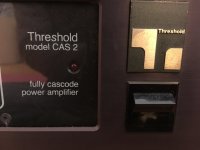
New member interested in valve equipment


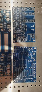
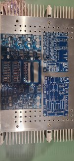
 https://flic.kr/p/2mybhNU
 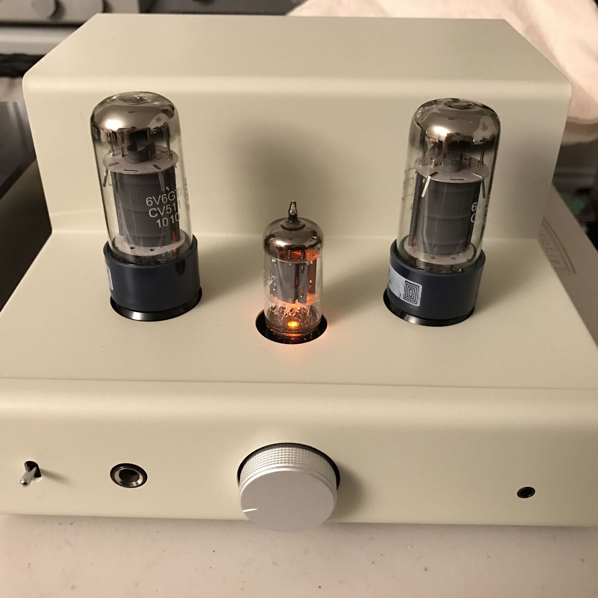 tu-8150 https://www.flickr.com/photos/64593884@N08/


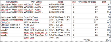
Manufacturer            Part Series             Value                   Pcs     New price per piece     Sum
Jantzen Audio Denmark   WAX Coil 16 AWG L       0.22mH / 0.15R          2       21      42
Jantzen Audio Denmark   WAX Coil 16 AWG L       0.75mH / 0.31R          2       30      60
Jantzen Audio Denmark   WAX Coil 16 AWG L       2.00mH / 0.57R          2       45      90
Jantzen Audio Denmark   WAX Coil 16 AWG L       3.30mH / 0.77R          2       57      114

Jantzen Audio Denmark   Superior Z-cap          3.3uF / 800Vdc / +-2%   2       25      50
Jantzen Audio Denmark   Superior Z-cap          22uF / 800Vdc / +-2%    2       110     220
ClarityCap              MR22uH400Vdc            22uF / 400Vdc           2       221     442
Obbligato Premium +     Audio Cap               33uF / 250 Vdc          2       38      76
Obbligato Premium +     Audio Cap               47uF / 250Vdc           2       49      98
Mundorf                 Mcap EVO SilverGold Oil 10uF / 450Vdc / +-3%    4       97      388
Mundorf                 Mcap EVO SilverGold Oil 4.7uF / 450Vdc / +-3%   2       63      126
Mundorf                 Mcap EVO SilverGold Oil 5.6uF / 450Vdc / +-3%   2       68      136
                        Silver Mica             10nF / 2%               4               0
                                                                                TOTAL   1842