You are using an out of date browser. It may not display this or other websites correctly.
You should upgrade or use an alternative browser.
You should upgrade or use an alternative browser.
Filters
Show only:
Krell reference amp schematic
- Solid State
- 2 Replies
Krell reference amp schematic could not find any information
Attachments

Replace drive for ALTIS AUdio Centauri
- By dontzknow
- Digital Source
- 0 Replies
Hello, iam looking for a friend. He have a cd player " ALTIS AUDIO CENTAURI ".
Inside is there should be a Philips CDM 12 industrial transport refer to all infos what i found.
As the unit is very old we want to replace the drive with the Philips CD Pro 2 MF - VAU1254/31LF (Cd Pro 804 C)
All that infos are the stickers and printed on the drive what we bought some years ago.
It can be swapped with the original drive with not much work-just a cover on the mechanical side.
So my questions are:
1)
As the new unit have a splitted analog and digital ground and the original not,
i want to know the pinning of the connection for power on the old industrial drive.
Every info is welcome, best of coarse are schematics, service manuals and more.
2)
Confusing is that the "user manual Premium 10501 " from the Philips CD Pro 2 MF - VAU1254/31LF (Cd Pro 804 C )
tells that the A/D grounds ar not connected on the PCB, but in reality they are. They PCB ground is connected over the mechanical metall chassis.
So i also search here for a real electrical schematic for the PCB.
The player is extremly seldom and have a seperate power supply and the company is not existend anymore as the owner passed away in the year 2002..
Iam a very skilled electronical/mechanical, but its stupid to start that kind of work with not enough knowledge infos.
So please, every help is sensefull and very welcome here.
Thanks Robert
Pioneer SA-7500ii output transistor question
- By DOM123
- Solid State
- 4 Replies
Hi Everyone,
Picked up an old & very dirty Pioneer SA-7500ii showing signs of past mishaps. The original output transistors 2SB618A & 2SD588A are present on one channel, but on the other channel they have been replaced with SC2579 & SA1104, with a hole drilled in the heatsink to mount them. From the filth & dust build-up it must have been done a long time ago. Also one of the emitter resistors is is not original & the board is quite severely charred beneath this resistor, so probably from the time of the original failure.
Has anyone ever heard of these transistors being used as a sub for 2SB618A & 2SD588A and should they be OK ? On paper the specs look ok & to be fair the amp seems to work ok. Should I just leave them in or replace all 4 transistors with new ones ?
I know on various forums other replacements transistors are proposed, but to be honest most are not easily available at a reasonal cost. I can quite easily get 2SC3858 & 2SA1494 though. Any advice welcome.
Darlington TO-3 okay for parallel output class AB Pioneer SX-1250? Ebay part arrived this way, not what I ordered...
- By TankAudio
- Solid State
- 3 Replies
Hi,
Always thankful for everyone's time and interest. I have received a part that I'm not sure is genuine. Can a part that tests as Darlington with Rshunt and w/ Protection Diode features be used in place of a standard TO-3 device? In my application - class AB power amp, where only the PNP's are Darlington - I think not, because the Vbe is double on the Darlington devices, so class AB signal switching won't line up properly.
I am repairing a Pioneer SX-1250, which has been blowing the main 12A fuse on startup. After testing the output devices, one bank of TO-3's has been found completely shorted. There are 4x total TO-3 devices per side: Parallel pairs. Neither side appears original. The good side has been tested with sig/scope and music, by disconnecting the power supply and driver board for the bad side. As it stands now, the working good side has 2SD555 and 2SB600 pairs (NPN and PNP, respectively), while the blown side has NTE87 and NTE88.
I have purchased 5 pairs of 2SD555 and 2SB600 parts from a vendor on eBay. The 2SB600's are the ones that test as Darlingtons, and so these are the one's I suspect to be questionable, as the datasheet for this part does not show either a Darlington schematic or mention of this arrangement. Tonight I pulled the known, good 2SB600's from the working side and they tested as standard ~.602 Vbe.
Equipment used for testing: Peak Atlas DCA75.
*Since we're on the shared topic of transistor matching, can I get a quick confirmation that Beta/Hfe testing is of primary importance when matching individual/solo (stereo) pairs of preamp/power devices, and Vbe testing is primarily important when matching parallel pairs? Thanks.
Elsinore Waveguide Loading or Crossover Point
I have purchased the Elsinore waveguide, the most recent one for a centre speaker I am designing with a hypex amp. I would like to know a little more about the waveguide especially as it's not common in size, shape or width for that matter, not matching my 4 inch woofer diameter that it will crossover to. (They usually say the waveguide needs to match the diameter of the crossing woofer)
What is the lowest crossover point I can use which will still ensure controlled directivity to my matching Scaspeak 12W/8524G00?
And the waveguide is not like any other it's slightly deep but not wide. What are the tradeoffs of this kind of waveguide and what is the design principal behind it?
What is interesting is I know that the crossover recommendation for this waveguide is somewhat of a higher point of around 3000 hz but as the waveguide is larger in size I have a C-C distance issue so on paper at least I would like to go lower.
Printing on panel in Front Panel Express
- By jan.didden
- Software Tools
- 2 Replies
I am trying to place a printed text on a front panel in Front Panel Express. I select Insert|Text Engraving and in the dialog box select "Always print this element". But I keep getting an error message: "Error, printing on this material is not possible. Please select a printable material or choose another option for engraving mode".
I tried selecting different materials, alu, perspex, with/without coating, for the panel but the error stays.
What am I doing wrong?
Jan
I tried selecting different materials, alu, perspex, with/without coating, for the panel but the error stays.
What am I doing wrong?
Jan
Fons CQ30 - power supply rebuild
- By kunlun121
- Analogue Source
- 2 Replies
As part of a project that involves a complete makeover of a Fons CQ30 turntable, I want to rebuild the power supply. The components are all ancient and the shape of the PCB is odd. No doubt this is due to its place in the turntable's enclosure, but i want to move it to a separate box. The elco on mine is most certainly dead.
As a noob (both to this forum and to diy audio) I wouldn't be able to do so if it weren't for the enclosed schematic I found over at Vinyl Engine. So a thank you to them.
Before I embark on making a new pcb from this schematic, I want to ask the open question: can any of the folks here with turntable expertise recommend straightforward ways for improving on the design of this power supply or the choice of components? (Without starting over with a blank piece of paper.) Anything that can improve the stability of the speed control for example. And I haven't checked but at least some of what is listed here must be obsolete.
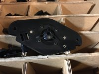
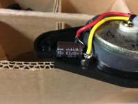
The only choices I have made are the easy ones: a rotary selection switch for the speed selection, and new (rotary) potentiometers for the pitch adjustment. I plan to replace the motor with a NOS unit from a Philips GA312 I ran into recently, as mine requires some manual help to start spinning. Apparently these are are a drop-in replacement for the CQ30's motor (unlike the Philips GA212's motor, which are easier to find but makes the platter spin at around 150RPM without adjustments).
All advice would be much appreciated.


As a noob (both to this forum and to diy audio) I wouldn't be able to do so if it weren't for the enclosed schematic I found over at Vinyl Engine. So a thank you to them.
Before I embark on making a new pcb from this schematic, I want to ask the open question: can any of the folks here with turntable expertise recommend straightforward ways for improving on the design of this power supply or the choice of components? (Without starting over with a blank piece of paper.) Anything that can improve the stability of the speed control for example. And I haven't checked but at least some of what is listed here must be obsolete.
The only choices I have made are the easy ones: a rotary selection switch for the speed selection, and new (rotary) potentiometers for the pitch adjustment. I plan to replace the motor with a NOS unit from a Philips GA312 I ran into recently, as mine requires some manual help to start spinning. Apparently these are are a drop-in replacement for the CQ30's motor (unlike the Philips GA212's motor, which are easier to find but makes the platter spin at around 150RPM without adjustments).
All advice would be much appreciated.
Slate & acryl DD tt
- By trondkj
- Analogue Source
- 23 Replies
Slate & acryl DD tt
Hi folks, my first serious post here, hope you'll enjoy.
It began with a Dual 701 DD turntable, a nice turntable, but with an arm that is not up to the specs I wanted. The automatics were malfunctioning, so I slaughtered the tt and bought an acrylic platter from Diy Hifi Supply.

I was thinking about the plint, should I make a aluminium-ply-mdf-ply-aluminium sandwich like this:?

..or go for something different?

I went for something different, and since then I have done a lot of thinking, and a little work:

The acrylic platter on top of the slate plint illuminated by the midnight sun
Last easter i got a hole in the slate so that the EDS1000 motor would fit in.

Before that I had installed the power supply and speed selector / pitch control in a box:

The turntable with the motor and platter installed:

..and with a couple of arm boards temporarily placed on top:

I nice member of this forum saw the picture above on a Norwegian forum, and offered to make a couple of acrylic arm boards for me:

For this turntable the arm(s) have to be DIY as well, I am going for a Ladegaard tangential on the left arm board, and a 12" Schröder copy on the right arm board.
But I do not have enough patience to wait for the arms to be finished, so one of my temporar arm boards have to do as a base for my SME 3009/S2 Impr. for so long.

Not willing to make holes in the stone for the arm screen under the base, I had to do a little modification to the arm:

The left arm board is mounted to the stone with brass standoff/legs:

The right one is only standing on its legs, but they are shinyer than the other ones:

And of course there's something that simply does not fit in, and therefore has to go:

I am thinking about a motor cover made of black transparent acryl to replace this wooden thing.
The turntable plays with a Shure M75ED 2 with a Jico SAS needle to plow the grooves, and sounds really promishing.
Kind regards
Trond Kjetil
Hi folks, my first serious post here, hope you'll enjoy.
It began with a Dual 701 DD turntable, a nice turntable, but with an arm that is not up to the specs I wanted. The automatics were malfunctioning, so I slaughtered the tt and bought an acrylic platter from Diy Hifi Supply.
I was thinking about the plint, should I make a aluminium-ply-mdf-ply-aluminium sandwich like this:?
..or go for something different?
I went for something different, and since then I have done a lot of thinking, and a little work:
The acrylic platter on top of the slate plint illuminated by the midnight sun
Last easter i got a hole in the slate so that the EDS1000 motor would fit in.
Before that I had installed the power supply and speed selector / pitch control in a box:
The turntable with the motor and platter installed:
..and with a couple of arm boards temporarily placed on top:
I nice member of this forum saw the picture above on a Norwegian forum, and offered to make a couple of acrylic arm boards for me:
For this turntable the arm(s) have to be DIY as well, I am going for a Ladegaard tangential on the left arm board, and a 12" Schröder copy on the right arm board.
But I do not have enough patience to wait for the arms to be finished, so one of my temporar arm boards have to do as a base for my SME 3009/S2 Impr. for so long.
Not willing to make holes in the stone for the arm screen under the base, I had to do a little modification to the arm:
The left arm board is mounted to the stone with brass standoff/legs:
The right one is only standing on its legs, but they are shinyer than the other ones:
And of course there's something that simply does not fit in, and therefore has to go:
I am thinking about a motor cover made of black transparent acryl to replace this wooden thing.
The turntable plays with a Shure M75ED 2 with a Jico SAS needle to plow the grooves, and sounds really promishing.
Kind regards
Trond Kjetil
Hypex Ncore NC500MP Mono module to sell. Europe only
- By daniboun
- Vendor's Bazaar
- 7 Replies
SOLD to close
SOLD TO CLOSE
SOLD TO CLOSE
Speaker unit suggestions for Valve Amplifier (Baby Huey)
Hi,
I'm trying to work out the budget for speaker units for the BH amp I'm planning on building.
Thinking of a Woofer + Midrange + Tweeter. How does one go about sizing the wattage specs for the these units. Any specific ones that someone can recommend would be a good starting point for me.
Will build the cabinets from scratch.
Thanks
Earl Josh
Retrofitting a GRS 2522 into an old Radio Shack CS-5 center channel
- By Vidgamer
- Planars & Exotics
- 5 Replies
I took an old Radio Shack CS-5, gutted the old Linaeum tweeter, and substituted the GRS 2522. (The old tweeter was not working well and I could not fix it.) I chose the CS-5 because I had existing RS LX-5 speakers, and thought it might make a good tonal match, but time does not seem to be kind to the Linaeum tweeters. The GRS 2522 looked like it might be a reasonable substitute, so I decided to give it a try.
I tested with REW (generating white noise) in a non-ideal location (speaker propped on other stuff, and near a wall and corner), and got the below result. Except for the dip at 8k, this is better than I expected. I managed to guesstimate the match with the woofer pretty well, and it's eerily flat through the important midrange.
Woofer and tweeter use 1st order crossovers, which seems like it could be problematic, but it matches up OK, based on this. I estimate the woofer crossover to be starting at about 1500Hz, and the tweeter at 4k, so there's a lot of overlap.
I need to do a more complete write-up, but thought in the meantime, someone might find this interesting and/or tell me what my 8k dip is from. I did add a series 2.2 ohm resistor to try to match levels, so it's possible that it brought the higher treble down more than lower treble, I suppose.

(Edit: fixed attachment)
I tested with REW (generating white noise) in a non-ideal location (speaker propped on other stuff, and near a wall and corner), and got the below result. Except for the dip at 8k, this is better than I expected. I managed to guesstimate the match with the woofer pretty well, and it's eerily flat through the important midrange.
Woofer and tweeter use 1st order crossovers, which seems like it could be problematic, but it matches up OK, based on this. I estimate the woofer crossover to be starting at about 1500Hz, and the tweeter at 4k, so there's a lot of overlap.
I need to do a more complete write-up, but thought in the meantime, someone might find this interesting and/or tell me what my 8k dip is from. I did add a series 2.2 ohm resistor to try to match levels, so it's possible that it brought the higher treble down more than lower treble, I suppose.
(Edit: fixed attachment)
WTB Manganine wire 0.1mm
- Swap Meet
- 0 Replies
Hi, i need some manganin enameled 0.1 mm wire ~60ohm/m to build some resistors.
Please PM if any has some spare .
Best regards!
Please PM if any has some spare .
Best regards!
WTB: TOSHIBA 2SK369-BL
I'm in a need for multiple pcs/pairs of 2SK369-BL. Used are also fine..
Offers in PM.
Thanks!
Offers in PM.
Thanks!
Peter Walker and his current dumping principle
- By revenant
- Solid State
- 125 Replies
Hi to u all ,
a long time ago peter walker and mike albiston patented the current dumping circuit in which a powerful class b amp took over from a little linear class amp to provide the muscle drive needed by hungry lodspeakers through a wheatstone bridge.I would like to know if that topology has been used by other manufacturers and if so,what are its advantages and disadvantages compared to other conventional circuits?thanks.
a long time ago peter walker and mike albiston patented the current dumping circuit in which a powerful class b amp took over from a little linear class amp to provide the muscle drive needed by hungry lodspeakers through a wheatstone bridge.I would like to know if that topology has been used by other manufacturers and if so,what are its advantages and disadvantages compared to other conventional circuits?thanks.
Jordan VTL / GM MLTL-31 hybrid
- By wallis61
- Full Range
- 11 Replies
Hi,
I'm interested in building my first single driver speakers but don't know enough yet to try an original design of my own.
The Jordan JX92s driver seems to be well respected and I like the wide baffle esthetics of the VTL. But from reading this forum, it seems like the GM MLTL-31 may sound better.
I notice that the CSA of the VTL and the GM MLTLs are almost identical. So my question is: can I use the cabinet volume and a port with same length from the MLTL-31, with the cabinet width and depth of the VTL and expect good results?
Also, how critical is the vertical placement of the driver? I like the look of the high driver placement of the VTL.
Thanks so much for such an interesting forum!
Wally
FS: Eminence Delta-15LFA Woofers (2) - $175 Shipped in CONUS
FS: Eminence Delta-15LFA Woofers (2) - $160 + split shipping
As close to new as you can get. Mounted in my folded OB speakers for a couple days, then pulled out. Powered with 45 SET amps, so not stressed in the least. They are backordered at PE:
Eminence Delta-15LFA 15" Low Frequency Driver
Will ship in the same packaging they came to me from PE in. I'll split actual shiping cost with the buyer. Look new, but I can get you pics if needed (they are boxed up). Thanks.
2SC1318 sub in flip flop circuit
I'm trying to sort out a Start/Stop problem in a turntable (see here) and want to try swapping out TR12, a 2SC1318. Any thoughts on whether a KSC2383 would be adequate in this location?

Steg 310.2
hello all!
i have a problem with a steg 310.2, it was working but it had the usual problem on the potentiometer wich made noise in the output, and unbalanced volumes in output..
so i desoldered it, cleaned and resoldered, after 5 minutes it goes in protection..
i checked the mosfets and teh Q64 was burn!, checked them all and replaced all the 6 mosfets on that side from the IRF540a with FQP33N10 as mentioned in the service manual..
but after 5 minutes of play i got protection again: this time was the Q63, replaced that one only, and after 5 minutes of music not at full volume same thing, q63 burn..
can it be a defective gain potentiometer the cause??
excepting from the unbalanced output it worked great form months!
EL34 triode mod
- By mongting
- Tubes / Valves
- 11 Replies
I got Jolida JD302B recently. The amplifier is EL34 PP with ultra linear. I would like to modify it as triode connection.

I got this schematic and

I was told to cut the connection to the pin #4 and put 100 ohm resistor between pin #3 and pin #4.
Then, I found another schematic about triode mod.

This one tells that I need to cut the connection to pin #3 which is connected to the plate of a tube. And it also shows the disconnection from the output transformer to C2.
I am confused now. Which one is right?
1) cut the connection to pin 3 and put 100 ohm resistor between 3 and 4.
2) cut the connection to pin 4 and put 100 ohm resistor between 3 and 4. additionally, cut the connection between the output transformer and C2.
I don't have much knowledge in circuit theory.
I got this schematic and
I was told to cut the connection to the pin #4 and put 100 ohm resistor between pin #3 and pin #4.
Then, I found another schematic about triode mod.
This one tells that I need to cut the connection to pin #3 which is connected to the plate of a tube. And it also shows the disconnection from the output transformer to C2.
I am confused now. Which one is right?
1) cut the connection to pin 3 and put 100 ohm resistor between 3 and 4.
2) cut the connection to pin 4 and put 100 ohm resistor between 3 and 4. additionally, cut the connection between the output transformer and C2.
I don't have much knowledge in circuit theory.
When to recap?
- By Old bones
- Solid State
- 19 Replies
I have noticed a lot of threads about repairing older units and advice about not paying too much for them because they might need recapping either right away or soon.
My amp (Sony TA-F450ESD) is from about 1980. It sounds fine to me but I can't say my ears are in top shape so was wondering..............
What would be the noticeable signals that would indicate it is time to reach for the soldering iron?
My amp (Sony TA-F450ESD) is from about 1980. It sounds fine to me but I can't say my ears are in top shape so was wondering..............
What would be the noticeable signals that would indicate it is time to reach for the soldering iron?
-
Locked
FS: Signal Transformers Altec, Jensen, Soweter, Onetics
I love transformer coupled audio circuits. But I have some transformers kicking around my parts box that need to find a new home.
$150 takes the lot. And I'll throw in some no name mic transformers.
$5 shipping each pair to USA and territories. PayPal or Venmo payment preferred. Outside USA please esquire, I'll check prices.
All working, just been sitting in the parts bin doing nothing for years. Put them in your projects and make them sing again!


$45 Pair: Altec/Peerless 15356 Octal base. Look old, sound great. Some solder on the pins.$35 Pair: Jensen JT-11-HFMPC Tested but never used.$40 Pair: Sowter type 3128. Short leads, pulled from a circuit board. Screw mount$45 Pair: Sowter 9809f. Original length leads.$20 Pair: Onetics microphone transformers. 1:1 has center tap (I think) Jensen shown for scale.
$5 shipping each pair to USA and territories. PayPal or Venmo payment preferred. Outside USA please esquire, I'll check prices.
All working, just been sitting in the parts bin doing nothing for years. Put them in your projects and make them sing again!
Sony Reference Discs
- By EUVL
- Digital Source
- 1 Replies
Hi,
I am sure it is beginner's mistake, so please don't laugh.
I have a sony SACD (XB940), which ceased to play SACDs one day though CDs are still fine. So I thought the laser had drifted and got myself a new laser unit, but that was even worse (won't even play CDs).
Then I digged up the service manual. Apparently the servos of the laser unit have auto-tune. And once should do that with a Sony reference disc HLX-501 (or 503, 504, 505).
Without that on hand, I tried with an ordinary SACD just in the hope that it would also work. And of course wishful thinking.
The reference disc is next to impossible to get and cost a fortune. I wonder if anyone can help / advice.
(PS I already had a look at the other thread for the Sony CD reference disc, but the reference number for the SACD is different.)
Many thanks in advance,
Patrick
A modern Mullard 5-20 circuit
- By kstagger
- Tubes / Valves
- 2 Replies
I have a Frankenstein version of the venerable Eico ST70, modified with no preamp section so it only operates as a basic power amplifier.
Gain is silly high - especially with a Audio Research SP-8 preamp. Short of rebuilding with a H-K Citation V circuit, what input tube would you use to replace the 12AX7?
See here for the 12AX7/6SN7/5881 circuit
http://tronola.com/html/st-70_mods.html
Gain is silly high - especially with a Audio Research SP-8 preamp. Short of rebuilding with a H-K Citation V circuit, what input tube would you use to replace the 12AX7?
See here for the 12AX7/6SN7/5881 circuit
http://tronola.com/html/st-70_mods.html
Source for 2SK3497 and 2SJ618
- By ridikas
- Solid State
- 2 Replies
I’m looking to purchase 8 of each 2SK3497 and 2SJ618 MOSFETs. I do not need them matched. They must be real and not the fake ones available on eBay. I’m willing to pay a premium. I’m located in Illinois United States. Please PM me your offer. I’m also looking for information on what equivalent parts could be substituted? If anyone has any information, it would be greatly appreciated. Thank you all in advance.
Lecson AP1 & AP2 Detailed Information
- By PMK145
- Solid State
- 1 Replies
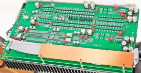
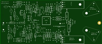
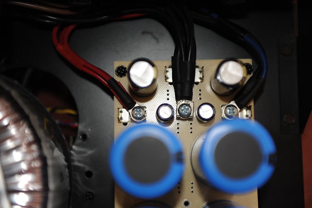
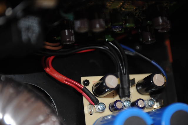
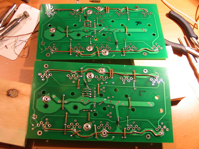
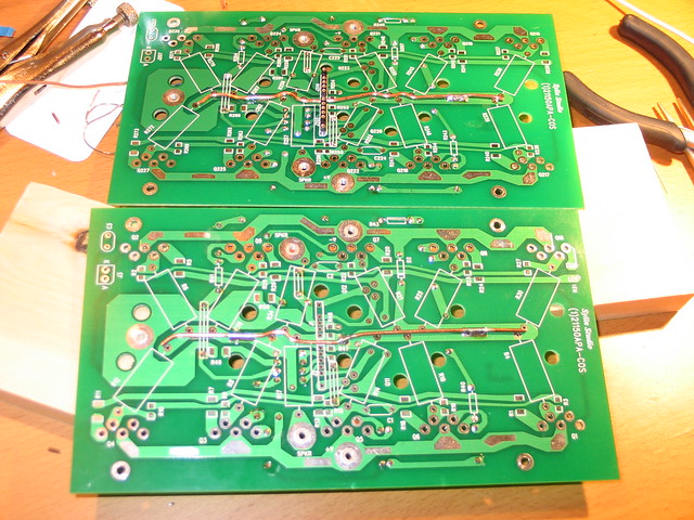
As an opportunity to learn a bit more about amplifiers and particularly transistors, I've bought a Lecson AP2 Power Amp that has a circuit board that's been burned by overheating components - the centre of the board is all but trashed. I'm designing a new circuit board with as far as possible, the components, the layout and tracks being identical to the original. According to the schematic (not the one in the AC1/AP1 Service Manual the 'other one') there are a few resistor changes that distinguish the AP1 from the AP2, but even that schematic is a little different from the manufactured item.
Does anybody have a high def image of the AP1 that would enable the resistor values to be identified? I'm interested to see if my new boards would enable the repair of an AP1. The tantalum capacitors at the front end on mine are 15 microfarad not 22 microfarad. I wonder how many versions of the AP1 & AP2 were produced?
Attached are images of my 'good' board and the top silkscreen of my prototype replacement. I believe somebody had previously replaced two 0R27 wirewound resistors with that pole of grey resistors
Attachments

Some diyAudio polls from the past
- By AllenB
- The Lounge
- 0 Replies
About 10 years ago for a short time this site was set to display random polls from current threads, on the home page. As a curiosity, these have been harvested from the wayback machine.
-----
What's your next project?
Source - 7.47% 18 Votes
Preamp - 20.75% 50 Votes
Amplifier - 42.32% 102 Votes
Loudspeaker - 24.90% 60 Votes
Other - 4.56% 11 Votes
-----
Do You Think Single-Ended Class-A Amplifiers Sound Best?
YES! - 40.45% 108 Votes
NO! - 19.10% 51 Votes
Nothing Special. Just Another Amplifier. - 22.10% 59 Votes
I Haven't Seen Such An Amplifier. - 18.35%
-----
Cat or Dog, Tubes or Sand?
Tubes + Cat - 23.81% 35 Votes
Tubes + Dog - 18.37% 27 Votes
Sand + Cat - 27.89% 41 Votes
Sand + Dog - 18.37% 27 Votes
Other (be nice to us and tell) - 11.56% 17 Votes
-----
Have i lost it or is it good?
You've got it totally wrong - 50.00% 2 Votes
You're overlooking other important things so it'd have no effect - 50.00% 2 Votes
There is cleverness in it, but you're not quite there yet - 50.00% 2 Votes
All hail the messiah of audio fidelity! - 75.00%
-----
well, do MC carts sound better than MM ones?
yep - 70.77% 46 Votes
nope - 29.23% 19 Votes
-----
Most neutral/least audible crossover topology?
B3 - 15.38% 2 Votes
LR4 - 7.69% 1 Vote
B5 - 0% 0 Votes
LR6 - 0% 0 Votes
B7 - 0% 0 Votes
LR8 - 0% 0 Votes
LR2 - 23.08% 3 Votes
none of the above - 53.85%
-----
Colour of the pcb
Red, white print and gold pads - 20.00% 4 Votes
Blue, white print and gold pads - 20.00% 4 Votes
Black, white print and gold pads - 30.00% 6 Votes
Black, yellow print and gold pads - 0% 0 Votes
Yellow, black print and gold pads - 0% 0 Votes
Green, white print and gold pads - 25.00% 5 Votes
White, black print and gold pads - 20.00% 4 Votes
White, red print and gold pads - 0% 0 Votes
-----
What's the highest frequency you can hear?
Up to 21kHz - 1.43% 1 Vote
Up to 20kHz - 0% 0 Votes
Up to 19kHz - 4.29% 3 Votes
Up to 18kHz - 17.14% 12 Votes
Up to 17kHz - 20.00% 14 Votes
Up to 16kHz - 22.86% 16 Votes
Up to 15kHz - 11.43% 8 Votes
Up to 14kHz - 12.86% 9 Votes
Up to 13kHz - 2.86% 2 Votes
Up to 12kHz - 7.14% 5 Votes
-----
Will MJL21193's crazy design work as proposed?
Yes - 49.30% 35 Votes
No - 8.45% 6 Votes
Maybe. - 29.58% 21 Votes
I'll laugh when it doesn't. - 12.68%
-----
What cabinet should jlux use?
Del Sol -Aura NS3 design - 5.26% 1 Vote
Milli Fonken - 10.53% 2 Votes
RS100 Transmission design - 26.32% 5 Votes
HEY- The best choice is none of these!!! - 57.89% 11 Votes
-----
To Glue or not to Glue, that is the question.
1 - Glue the covers on at the Factory. - 0% 0 Votes
2 - Leave loose, let end users choose to use or discard cover. - 87.50% 35 Votes
3 - Offer both glued and loose cover options. - 12.50% 5 Votes
-----
What's your next project?
Source - 7.47% 18 Votes
Preamp - 20.75% 50 Votes
Amplifier - 42.32% 102 Votes
Loudspeaker - 24.90% 60 Votes
Other - 4.56% 11 Votes
-----
Do You Think Single-Ended Class-A Amplifiers Sound Best?
YES! - 40.45% 108 Votes
NO! - 19.10% 51 Votes
Nothing Special. Just Another Amplifier. - 22.10% 59 Votes
I Haven't Seen Such An Amplifier. - 18.35%
-----
Cat or Dog, Tubes or Sand?
Tubes + Cat - 23.81% 35 Votes
Tubes + Dog - 18.37% 27 Votes
Sand + Cat - 27.89% 41 Votes
Sand + Dog - 18.37% 27 Votes
Other (be nice to us and tell) - 11.56% 17 Votes
-----
Have i lost it or is it good?
You've got it totally wrong - 50.00% 2 Votes
You're overlooking other important things so it'd have no effect - 50.00% 2 Votes
There is cleverness in it, but you're not quite there yet - 50.00% 2 Votes
All hail the messiah of audio fidelity! - 75.00%
-----
well, do MC carts sound better than MM ones?
yep - 70.77% 46 Votes
nope - 29.23% 19 Votes
-----
Most neutral/least audible crossover topology?
B3 - 15.38% 2 Votes
LR4 - 7.69% 1 Vote
B5 - 0% 0 Votes
LR6 - 0% 0 Votes
B7 - 0% 0 Votes
LR8 - 0% 0 Votes
LR2 - 23.08% 3 Votes
none of the above - 53.85%
-----
Colour of the pcb
Red, white print and gold pads - 20.00% 4 Votes
Blue, white print and gold pads - 20.00% 4 Votes
Black, white print and gold pads - 30.00% 6 Votes
Black, yellow print and gold pads - 0% 0 Votes
Yellow, black print and gold pads - 0% 0 Votes
Green, white print and gold pads - 25.00% 5 Votes
White, black print and gold pads - 20.00% 4 Votes
White, red print and gold pads - 0% 0 Votes
-----
What's the highest frequency you can hear?
Up to 21kHz - 1.43% 1 Vote
Up to 20kHz - 0% 0 Votes
Up to 19kHz - 4.29% 3 Votes
Up to 18kHz - 17.14% 12 Votes
Up to 17kHz - 20.00% 14 Votes
Up to 16kHz - 22.86% 16 Votes
Up to 15kHz - 11.43% 8 Votes
Up to 14kHz - 12.86% 9 Votes
Up to 13kHz - 2.86% 2 Votes
Up to 12kHz - 7.14% 5 Votes
-----
Will MJL21193's crazy design work as proposed?
Yes - 49.30% 35 Votes
No - 8.45% 6 Votes
Maybe. - 29.58% 21 Votes
I'll laugh when it doesn't. - 12.68%
-----
What cabinet should jlux use?
Del Sol -Aura NS3 design - 5.26% 1 Vote
Milli Fonken - 10.53% 2 Votes
RS100 Transmission design - 26.32% 5 Votes
HEY- The best choice is none of these!!! - 57.89% 11 Votes
-----
To Glue or not to Glue, that is the question.
1 - Glue the covers on at the Factory. - 0% 0 Votes
2 - Leave loose, let end users choose to use or discard cover. - 87.50% 35 Votes
3 - Offer both glued and loose cover options. - 12.50% 5 Votes
Tube redundancy between amp and preamp?
- Tubes / Valves
- 14 Replies
Hi all. Tube neophyte here with a potentially stupid question. Please bear with me.
I already own a tube preamp which is currently feeding a solid state amplifier. I am interested in adding a <5 watt valve amplifier to my listening room. I see many of the designs I'm looking at have tubes on the input stage like a 12ax7 or 6j1, as well as their output stage tubes. Is this going to be redundant or unnecessary since I already have the tube preamp? Should I just be looking for plans to build a model that is valve output only, to simplify the design and reduce cost? Is a tube input signal chain "too many" tubes?
Thanks for your patience.
Why do drivers with a low EBP reach down so deep in a BR alignment?
- Multi-Way
- 1 Replies
We've all been told an EBP fifty and lower is the more "suitable" choice as sealed for your favorite woofer...but when I model out these drivers in a BR alignment, the graphing has said drivers reaching way deep as to easily pass thru 20 hertz flat as a pancake. So what are those "tragic" consequences of this :unsuited" driver in this alignment.?
EG...GRS RSRMO-8
125W
90 Db
2.25 " VC
fs 22 Hz
Re 7.2
Le 1.82 mH
Qms 4.94
Qes 0.63
Qts 0.56
Vas 342.35 L
X 2.5 mm
----------------------------------------------------------------------------------------------------------------------------------------------Rick....................................
EG...GRS RSRMO-8
125W
90 Db
2.25 " VC
fs 22 Hz
Re 7.2
Le 1.82 mH
Qms 4.94
Qes 0.63
Qts 0.56
Vas 342.35 L
X 2.5 mm
----------------------------------------------------------------------------------------------------------------------------------------------Rick....................................
2x12 and 1,4 coax CD Synergy
- By petterhaus
- Multi-Way
- 100 Replies
Hi
I'm Alessandro from Italy
My english is not very good.
This is my first synergy project. I've planned it for many months reading almost every threads about MEH on the web especially on diyaudio so I deciced to subcribe here and say BIG THANK YOU for the immense knowledge and passion
without being hungry when different opinions are involved
(italian forums are diametrically opposite, my bad).
My idea was initially to replace 2x MACKIE SA1521 (133db max and 46kg) with
something with same or higher spl and less weight and max same dimensions to fit on a wagon car.
Immediatly I've found BFM DR series, good sensitivity but not high power handling.
When I've seen first Synergy pictures and threads I felt in love 😱
In the same time the Peter Morris PM90 i think are no brainer for quality, dispersion, high output, dimension and weight.
So I decided to design a 80x50 Synergy with:
2x rcf mb12n351
1x b&c dcx464
YES the same drivers suitable for PM90.
So if my synergy attemp is crap I will make pm90.
Tomorrow 😀 maybe the drivers will arrive from TLHP-france.
I have a diy steel 900mmx450mmx170mm so I would use for this project.
Meanwhile I have some questions:
1-80x50 coverage is good for me because I can implement 2x12 in 600Wx350Hx430DEPTH and horizontal pattern control is 300hz according to Bwalso speadsheet v5 (immense thank you) but is unual for a synergy, however is exactly 1.6 ratio.
2- with coax CD I can cover mids without cones and mid ports location "problem" so can I move 12"s a little far away from CD?
3-I want to extend frequecy to 100-110hz to use with subs. My hornresp AP-AP1 parameter selections are correct simulating reflex ports inside the horn?
4- on diyaudio DCX464 I read throat exit angle of this driver is 0°. I've tried to design on Fusion 360 (loft function) a round to rectangle using 80x50 angles to smooth CD throat. Can I have problem with distortion? Can I do it better maybe with first segment at 0°?
In Attached Hornresp 4pi simulations, Designs on Fusion without secondary flare.
Thank you very much
Ale
View attachment 956830
View attachment 956831
View attachment 956832
View attachment 956833
View attachment 956834
View attachment 956835
View attachment 956836
FS: Iso Tango / Hashimoto transformers
- By Geluidloopt
- Swap Meet
- 8 Replies
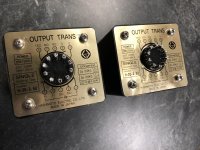
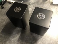
FS:
One pair of Hashimoto 20-3.5U Output transformers
3.5K into 16/8/4 ohm
Asking 450€/pair
Will ship worldwide
One pair of Hashimoto 20-3.5U Output transformers
3.5K into 16/8/4 ohm
Asking 450€/pair
Will ship worldwide
Attachments
Low noise Balanced MC Pre
- By Bonsai
- Analogue Source
- 436 Replies
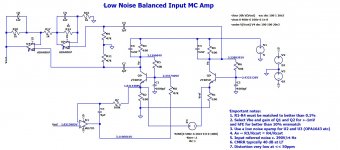
Here's a simple circuit I've been playing with for a balanced input MC pre. I'll do a bit more work on it in the coming few weeks. Its a pretty low cost approach - the most expensive item being a decent dual opamp like the OPA1642 for example. The noise will improve with higher collector currents, but a practical limit would be about 6-8 mA per side - any higher than this and the 5-8V reg will probably need a series pass device.
Note carefully the comments about resistor matching for R1-R4 - the CMRR depends on it!
U1 servos out any DC voltage difference across the emitters of Q1 and Q2 to ensure DC current through the cartridge is minimized. In practice, an OPA2188/9 would be used for this function (I just used the AD745 because this is what was in the LTspice library) as I have done in the X-Altra MC/MM RIAA (that is an unbalanced input, but lower noise). The other half of the servo can be used for the 5-8V reg - the PSRR of these devices is superb, so they work well in low noise servo and low noise regulator functions.
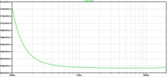
Update 02 January 2022 - I have added the PRELIMINARY 1st cut measurements - see PDF file below
Note carefully the comments about resistor matching for R1-R4 - the CMRR depends on it!
U1 servos out any DC voltage difference across the emitters of Q1 and Q2 to ensure DC current through the cartridge is minimized. In practice, an OPA2188/9 would be used for this function (I just used the AD745 because this is what was in the LTspice library) as I have done in the X-Altra MC/MM RIAA (that is an unbalanced input, but lower noise). The other half of the servo can be used for the 5-8V reg - the PSRR of these devices is superb, so they work well in low noise servo and low noise regulator functions.
Update 02 January 2022 - I have added the PRELIMINARY 1st cut measurements - see PDF file below
Attachments
Help with F5 with Gamut style MOSFET's
- By Uunderhill
- Pass Labs
- 132 Replies
I am tweaking an F5 Amp and using IXFN 180 n10 and IXTN 170 p10p power MOSFET's.
http://ixdev.ixys.com/DataSheet/98546.pdf
The channel resistance of these is less than 0.012 ohms - that's not a typo.
Have lowered the current detecting resistors R11 and R12 to 0.1 ohm
and changed resistors controlling the current limiting bi polar transistor appropriately.
Have prototyped these MOSFET's in Aleph style amps and the F5 biased at 0.4 amps.
The sound is jaw dropping.
However, these power MOSFET's have 10 times the transconductance of the
power MOSFET's spec'ed for the F5.
Because the transconductance is 10 times, I am concerned about thermal run away,
and do not want to be a member of FAB (N.P. refers to them as Fearless Audio Builders).
So, I either lower the voltage gain of the first stage, or increase the Feedback.
any recommendations ?
Thanks,
For Sale Super cheap, good dome tweeters
- By Bobulator55
- Swap Meet
- 0 Replies
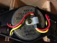
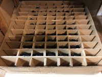
| New old stock 3/4" Delphi tweeters as shown, pricing is $8 for a set of 4. However I have a large supply of them, let me know if you want large quantities of them for a Line Array or whatever and I'll discount: 10 for $20, 50 (a box as pictured) for $75, or sell you my entire lot (like 600) for $1 per! Shipping separate. Includes a 4.7 uf crossover cap, but you can remove if you prefer a more sophisticated or customized xover. 4 Ohm, approx 3/4 " diameter dome tweeter. They sound really good, I used them in some speakers in the past. Inventory clearance! bobdrake55@gmail.com. |
Attachments


I pimped my Citation Sixteen! (or, resurrected?)
- By nattawa
- Solid State
- 5 Replies
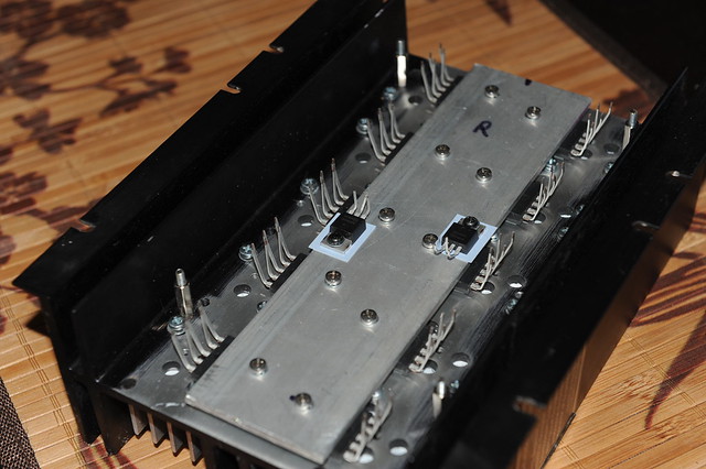
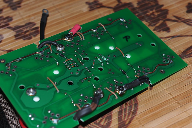
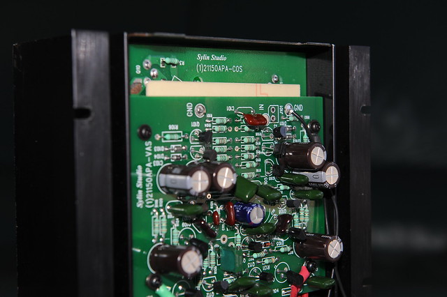
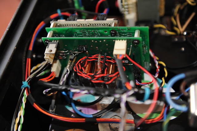
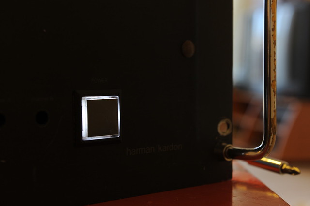
Bought a beaten-up Harman Kardon Citation 16 as a fixer-up unit and thought I’d fix whatever went wrong and it’d be my sleeper amp, only to end up with gutting this legend out completely. Now this amp has nothing but chassis and heat-sinks that are left over from the Citation Sixteen. It has two-channel Leach amp in it, with an output stage consists of 5-pair/channel ThermalTrak devices, NJL3281/1032 of On-Semi. By the way, could this be the first Leach Amp on TermalTrak output devices in this forum? Any ways here go the pics:
ALL-BUCKLED-UP...will it be a rough ride?
LITTLE DRIVERS…Can they handle the ark?
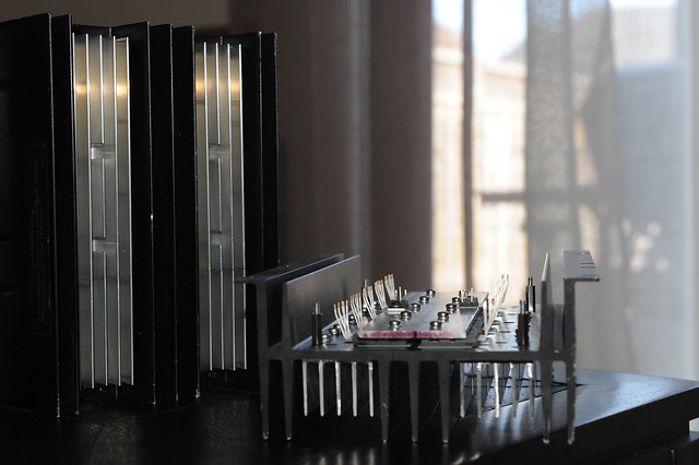
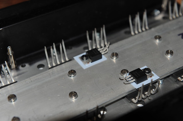
HEAT-AND-ITS-SINK
I piggy-back bolted some extra aluminum--scrap extrusion yet not particularly cheap🙁 from ebay-- to the center channel of the original Citation 16 heat-sink where the TO3s used to be to hopefully beef-up the heat-sinking capacity.
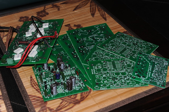
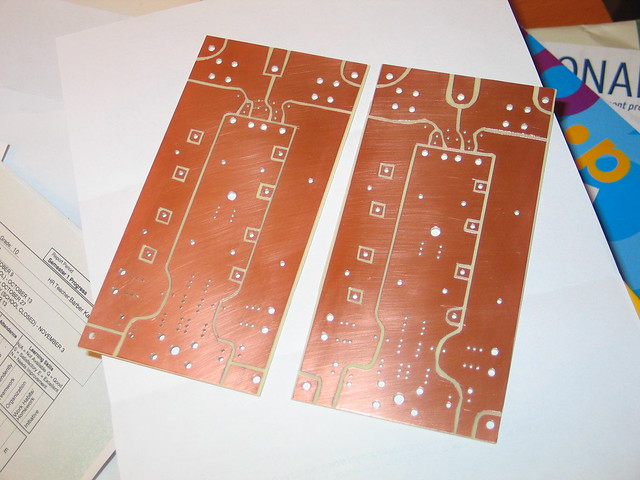
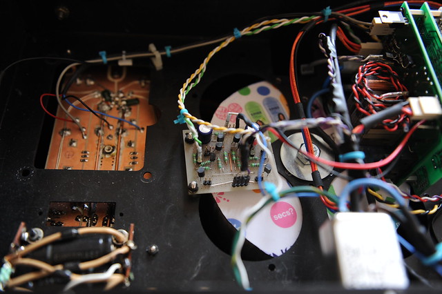
PCBS
Got these fabricated in China , cheap and in better-than-okay quality
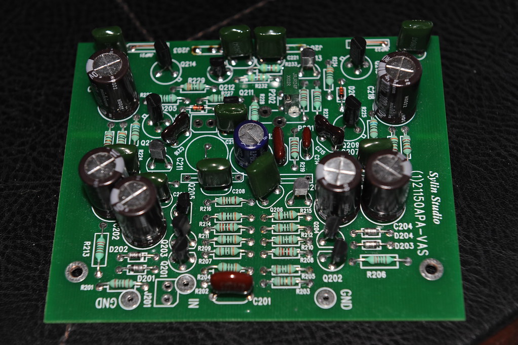
VAS
Voltage Amplification Stage assembled. I cut the GND copper foil to give the driver supply filter and the amplification stage supply filter separate ripple return paths after the PCB were made. The cuts show up on the component side as light marks mid way along the sides to the board edges
POWER-SUPPLY-BOARDS
These are hand-cut with a knife. The copper foils were later re-enforced with bus bars
PWR-CONNECTORS
Ring lugs over Erni Power-Tap was my choice of power connection
POWER CONNECTIONS
Each Power-Tap connector receives 2 ring lugs. For the center GND there are 7 wires, 3 of them form a triple #14 gauge going to the speaker binding post, the other4 are driver supply filter return, amplification stage supply filter return, output zobel GND lead, and the signal GND reference. For the power connections there are 3 wires per each rail, one goes to the amplification and driver stage, and #14 doubled go to the output transistor common rail. Why double/triple the wires you ask? The butt end of my ring lugs is too large for a #14 stranded, plus they all say size matters😉
BUS-BAR-BOT-COS
Current output board gets bus bars on the supply rails. I also put in pem nuts for easy attachment of the ring lugs. They were first pressed on the PCB into the plated holes, then got soldered to the copper foil.
BUS-BAR-TOP-COS
The output node gets a bus bar too
COS-BOT-WIRING
Ring lugs made doubled-up wiring easy
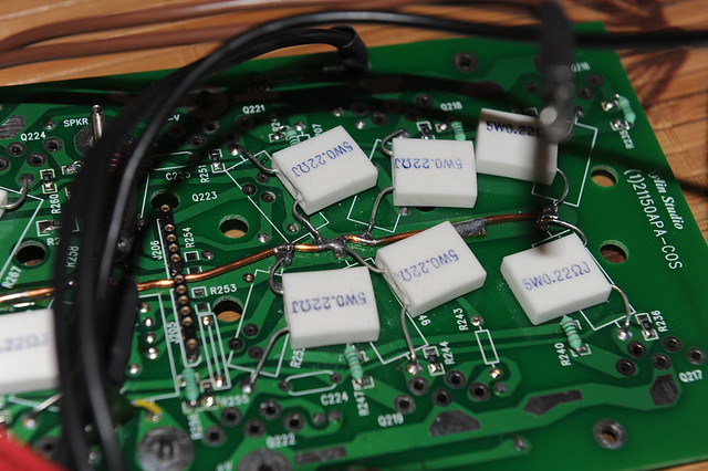
COS-DETAIL
Emitter resisters hooked up to the bus bar
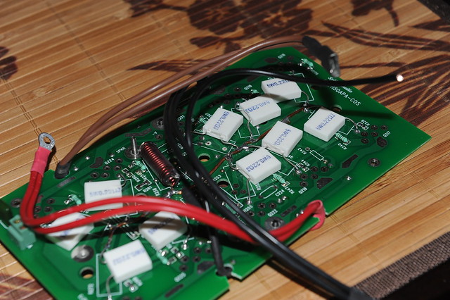
COS-WIRING
Current output stage ready to go onto the transistor/heat-sink assembly. Oh, noticed the 2-conductor terminal block at about the lower left corner in the picture? They are temperature sensor terminals reserved for on-die temperature measurement or warning/protection. Four out of the 10 ThermalTrak diodes are hooked up in series and wired up to this terminal block.
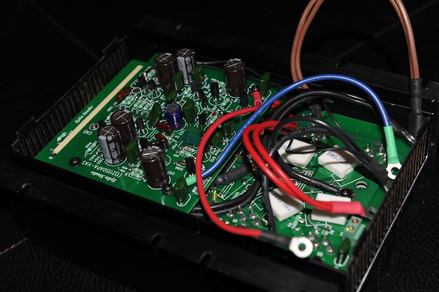
MODULAR-AMP
This is how the thing looks
THE SHIELD
I sandwiched a third PCB of solid copper foil on GND in between the VAS and COS to cut down any possible capacitive couplings between the output stage and the input stage.

AMP-MODULE
Ready to go on the chassis and rock
AMP-OFF-CHASSIS
Powered up for the first time......with fingers crossed......
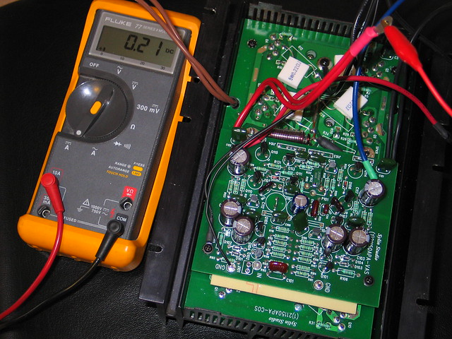
BIAS-ADJ
Started bias adjustment. I finally set the idle at 400mA to give the heat-sinks a nice warm touch. Stability has been good so far since the amp went into service a few months ago.
LEFT-CHNL-TOP
Left channel is on the chassis. The Neutrik RCA jacks look good, don’t they?
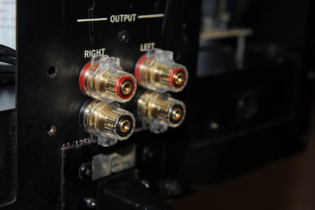
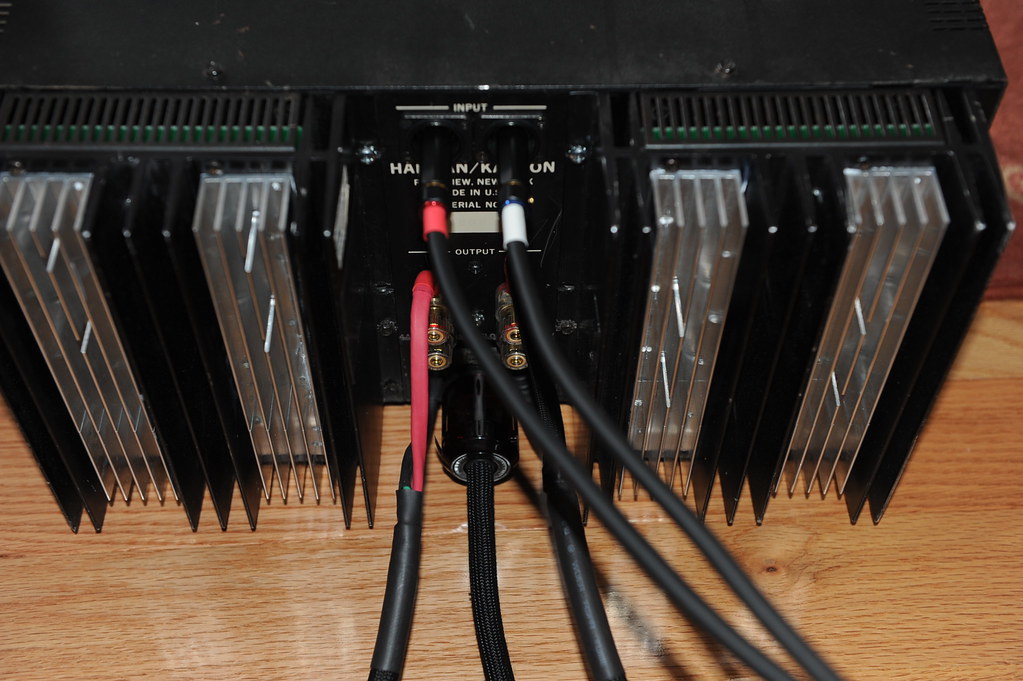
BINDING-POSTS
Are they too good?
R-CHNL-OFF-BINDPOSTS
Another view with right channel off chassis

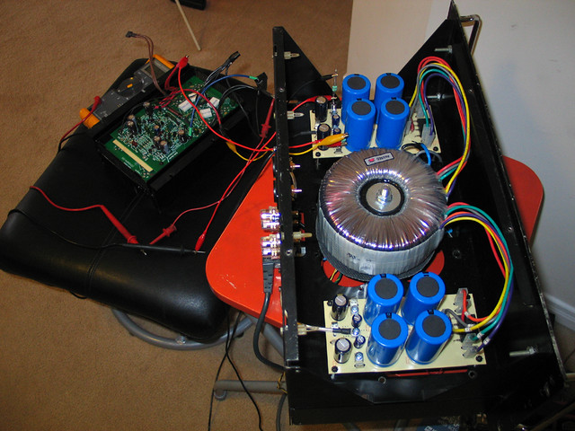
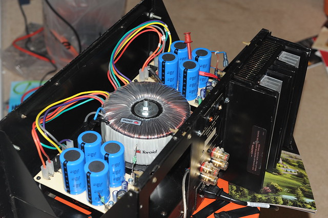
TOP-VIEW
All put together! This is the "living room" of the chassis. The two black blocks sitting next to the RCA jacks are the speaker relays. These are automotive relays with 80A contact capacity. The transformer looks nice in the chassis to me, despite the fact it was scavenged from a broken Behringer EP2500 power amp.
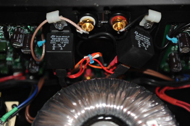
spk-rly-RCA-jack
A close up view
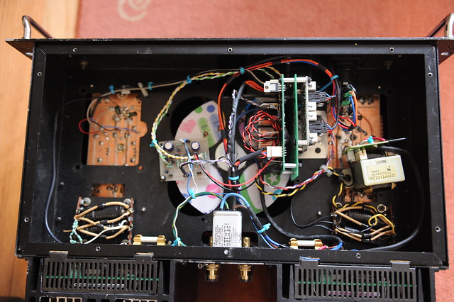
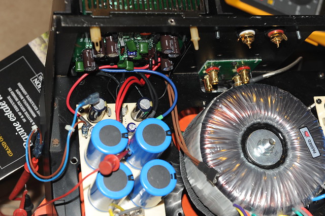
BOT-VIEW
Let's go to the basement and take a look at all the supporting components. There are a few assemblies there, working on a secondary power supply. The secondary power supply transformer was scavenged from a broken CD player
INRUSH-LIMITING
This PCB has three relays of 12A AC contact capacity on board for the mains. One to connect through thermisters, the other two in parallel bypass the in-rush control when the rails have become stabilized. It also controls two out-board relays to cut in and out speakers. (more on this later). The coiled up twisted black/red wires in the middle (a bit unsightly) are not connected at this time. They are reserved for working with protection mechanisms to shutting down the power. The PCB in green behind the inrush board is a piece of scrap and work as a supporting base for other PCB assemblies to attach to.

DISCHARGR
It discharges all 4 power rails quickly when power is turned off. (more on this later) The black chunk in the lower right is the power switch with lighting. It came with 12V incandescent bulb in it, but I don’t like the yellowish color so I replaced the bulb with 4 white LEDs in series.
DC-DETECTION
It sends fault signals to the inrush PCB to have the speaker relay(s) cut out when DC is detected. It also lights up a warning LED indicating the channel in trouble.
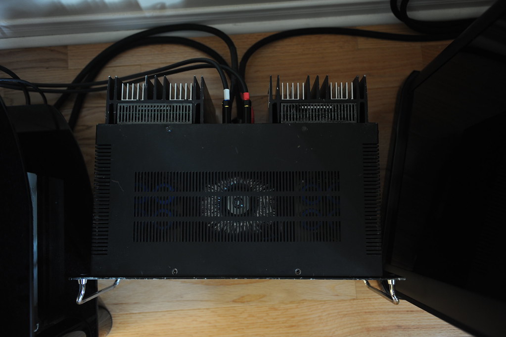
IN-SVCE-TOP
Case closed.
IN-SVCE-REAR
Ain’t her rear end smokin’ hot? 😉
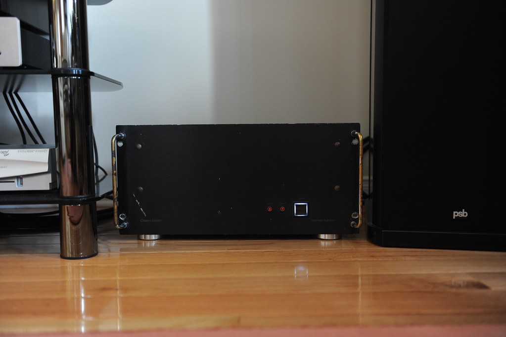
IN-SERVICE-Front
Hey, how do you like her in new shiny shoes? The original neon bulbs in the fixture have been replaced with LEDs that serve as DC warning. They seem to be glowing in the picture but they are in fact not. When they do they’d be much brighter than that.
My Paul-Sue-Barton’s are happy. So is the wifie. Beethoven has never sounded more Beethovenian.
TOE-OPERATED
The power switch is a push-button momentary switch so that one could easily operate with a toe and save his/her back. Here is how to:
http://www.flickr.com/photos/21102007@N04/4833640424/in/set-72157624460926929/
I’d get my dog to learn to do that for me if I had one.
About the Inrush PCB: (schematic will follow)
The big toroidal power transformer of over 1KVA and 80,000uF smoothing capacitance have made inrush current limiting a must. This circuit is based on hard-wired logic/timer devices, it controls the mains power relays and speaker relays. It works on a 12VDC secondary supply. This was laid out on a two-sided PCB that requires some basic SMT soldering skills to assemble. The circuit works with a lighted push-button switch with momentary contacts as the power switch, each push starts a 5-second time window during which the switch itself is disabled and the switch lamp flashes. When start from standby the soft-start relay will engage for as long as the time window lasts (5s), the mains power is applied through three GE CL-40 NTC thermister in series (15 ohms in total at room temperature). This will limit the inrush current and charge up the main caps in a controlled manner. The main caps should be charged up well within the 5-s time window and the rail voltage flats out. A flat-out detection circuit will engage a power-good monitor and if a power-good is positive the circuit enters power-on mode, the main relays (two in parallel) will bypass the inrush limiter and connect the primary winding of the power transform directly to the mains supply, the lamp in the power switch stops flashing to glow at a normal brightness, the speaker relays will also engage at the same moment given that there is no DC detected at the amplifiers’ output. The soft-start relay then cuts out at the end of the 5-s time window. If no power rail flat-out is detected or no power-good is detected during the 5-s time window, the main relays and the speaker relays will not engage, and the circuit returns to standby mode at the end of the time window, the lamp in the power switch then stops flashing to glow a dim light. Pushing the power switch during power-on mode will simply disengage power relays and speaker relays, and a 5-s time window follows to allow the main caps to be discharged deeply enough prior to responding next button push.
About the Discharger: (schematic will follow)
It brings main caps down to under 5V a few seconds of power off. It was built on prototyping board. The discharger is engaged whenever all the mains power relays cut out, and disengaged when any of the mains relays actuates. There are 4 jumpers on the board that allow for disabling the discharging operation. I used 4 photo couplers to isolate the control side from the audio GND, as well as audio GNDs of left and right channels. Such isolation also allows a very simple and uniform circuit implementation on all power rails using power MOFETs of one single model.
DC detecting circuit: (schematic will follow)
It works in tandem with the soft-start PCB to cut out speakers when DC presents at the amplifier output, it lights up a warning LED of the channel in trouble too. Built on prototyping board.
To be implemented: (schematic suggestion welcome)
An on-die temperature measurement/warning/protection using the roughed-in temperature sensor.
ALL-BUCKLED-UP...will it be a rough ride?
LITTLE DRIVERS…Can they handle the ark?
HEAT-AND-ITS-SINK
I piggy-back bolted some extra aluminum--scrap extrusion yet not particularly cheap🙁 from ebay-- to the center channel of the original Citation 16 heat-sink where the TO3s used to be to hopefully beef-up the heat-sinking capacity.
PCBS
Got these fabricated in China , cheap and in better-than-okay quality
VAS
Voltage Amplification Stage assembled. I cut the GND copper foil to give the driver supply filter and the amplification stage supply filter separate ripple return paths after the PCB were made. The cuts show up on the component side as light marks mid way along the sides to the board edges
POWER-SUPPLY-BOARDS
These are hand-cut with a knife. The copper foils were later re-enforced with bus bars
PWR-CONNECTORS
Ring lugs over Erni Power-Tap was my choice of power connection
POWER CONNECTIONS
Each Power-Tap connector receives 2 ring lugs. For the center GND there are 7 wires, 3 of them form a triple #14 gauge going to the speaker binding post, the other4 are driver supply filter return, amplification stage supply filter return, output zobel GND lead, and the signal GND reference. For the power connections there are 3 wires per each rail, one goes to the amplification and driver stage, and #14 doubled go to the output transistor common rail. Why double/triple the wires you ask? The butt end of my ring lugs is too large for a #14 stranded, plus they all say size matters😉
BUS-BAR-BOT-COS
Current output board gets bus bars on the supply rails. I also put in pem nuts for easy attachment of the ring lugs. They were first pressed on the PCB into the plated holes, then got soldered to the copper foil.
BUS-BAR-TOP-COS
The output node gets a bus bar too
COS-BOT-WIRING
Ring lugs made doubled-up wiring easy
COS-DETAIL
Emitter resisters hooked up to the bus bar
COS-WIRING
Current output stage ready to go onto the transistor/heat-sink assembly. Oh, noticed the 2-conductor terminal block at about the lower left corner in the picture? They are temperature sensor terminals reserved for on-die temperature measurement or warning/protection. Four out of the 10 ThermalTrak diodes are hooked up in series and wired up to this terminal block.
MODULAR-AMP
This is how the thing looks
THE SHIELD
I sandwiched a third PCB of solid copper foil on GND in between the VAS and COS to cut down any possible capacitive couplings between the output stage and the input stage.
AMP-MODULE
Ready to go on the chassis and rock
AMP-OFF-CHASSIS
Powered up for the first time......with fingers crossed......
BIAS-ADJ
Started bias adjustment. I finally set the idle at 400mA to give the heat-sinks a nice warm touch. Stability has been good so far since the amp went into service a few months ago.
LEFT-CHNL-TOP
Left channel is on the chassis. The Neutrik RCA jacks look good, don’t they?
BINDING-POSTS
Are they too good?
R-CHNL-OFF-BINDPOSTS
Another view with right channel off chassis
TOP-VIEW
All put together! This is the "living room" of the chassis. The two black blocks sitting next to the RCA jacks are the speaker relays. These are automotive relays with 80A contact capacity. The transformer looks nice in the chassis to me, despite the fact it was scavenged from a broken Behringer EP2500 power amp.
spk-rly-RCA-jack
A close up view
BOT-VIEW
Let's go to the basement and take a look at all the supporting components. There are a few assemblies there, working on a secondary power supply. The secondary power supply transformer was scavenged from a broken CD player
INRUSH-LIMITING
This PCB has three relays of 12A AC contact capacity on board for the mains. One to connect through thermisters, the other two in parallel bypass the in-rush control when the rails have become stabilized. It also controls two out-board relays to cut in and out speakers. (more on this later). The coiled up twisted black/red wires in the middle (a bit unsightly) are not connected at this time. They are reserved for working with protection mechanisms to shutting down the power. The PCB in green behind the inrush board is a piece of scrap and work as a supporting base for other PCB assemblies to attach to.
DISCHARGR
It discharges all 4 power rails quickly when power is turned off. (more on this later) The black chunk in the lower right is the power switch with lighting. It came with 12V incandescent bulb in it, but I don’t like the yellowish color so I replaced the bulb with 4 white LEDs in series.
DC-DETECTION
It sends fault signals to the inrush PCB to have the speaker relay(s) cut out when DC is detected. It also lights up a warning LED indicating the channel in trouble.
IN-SVCE-TOP
Case closed.
IN-SVCE-REAR
Ain’t her rear end smokin’ hot? 😉
IN-SERVICE-Front
Hey, how do you like her in new shiny shoes? The original neon bulbs in the fixture have been replaced with LEDs that serve as DC warning. They seem to be glowing in the picture but they are in fact not. When they do they’d be much brighter than that.
My Paul-Sue-Barton’s are happy. So is the wifie. Beethoven has never sounded more Beethovenian.
TOE-OPERATED
The power switch is a push-button momentary switch so that one could easily operate with a toe and save his/her back. Here is how to:
http://www.flickr.com/photos/21102007@N04/4833640424/in/set-72157624460926929/
I’d get my dog to learn to do that for me if I had one.
About the Inrush PCB: (schematic will follow)
The big toroidal power transformer of over 1KVA and 80,000uF smoothing capacitance have made inrush current limiting a must. This circuit is based on hard-wired logic/timer devices, it controls the mains power relays and speaker relays. It works on a 12VDC secondary supply. This was laid out on a two-sided PCB that requires some basic SMT soldering skills to assemble. The circuit works with a lighted push-button switch with momentary contacts as the power switch, each push starts a 5-second time window during which the switch itself is disabled and the switch lamp flashes. When start from standby the soft-start relay will engage for as long as the time window lasts (5s), the mains power is applied through three GE CL-40 NTC thermister in series (15 ohms in total at room temperature). This will limit the inrush current and charge up the main caps in a controlled manner. The main caps should be charged up well within the 5-s time window and the rail voltage flats out. A flat-out detection circuit will engage a power-good monitor and if a power-good is positive the circuit enters power-on mode, the main relays (two in parallel) will bypass the inrush limiter and connect the primary winding of the power transform directly to the mains supply, the lamp in the power switch stops flashing to glow at a normal brightness, the speaker relays will also engage at the same moment given that there is no DC detected at the amplifiers’ output. The soft-start relay then cuts out at the end of the 5-s time window. If no power rail flat-out is detected or no power-good is detected during the 5-s time window, the main relays and the speaker relays will not engage, and the circuit returns to standby mode at the end of the time window, the lamp in the power switch then stops flashing to glow a dim light. Pushing the power switch during power-on mode will simply disengage power relays and speaker relays, and a 5-s time window follows to allow the main caps to be discharged deeply enough prior to responding next button push.
About the Discharger: (schematic will follow)
It brings main caps down to under 5V a few seconds of power off. It was built on prototyping board. The discharger is engaged whenever all the mains power relays cut out, and disengaged when any of the mains relays actuates. There are 4 jumpers on the board that allow for disabling the discharging operation. I used 4 photo couplers to isolate the control side from the audio GND, as well as audio GNDs of left and right channels. Such isolation also allows a very simple and uniform circuit implementation on all power rails using power MOFETs of one single model.
DC detecting circuit: (schematic will follow)
It works in tandem with the soft-start PCB to cut out speakers when DC presents at the amplifier output, it lights up a warning LED of the channel in trouble too. Built on prototyping board.
To be implemented: (schematic suggestion welcome)
An on-die temperature measurement/warning/protection using the roughed-in temperature sensor.
Remote control stepped attenuator for tube preamp - choices?
- By andyjevans
- Tubes / Valves
- 13 Replies
What are the choices now in 2021/22 for a stepped attenuator with a remote control? I want to add one to a type 47 preamp, so around 100K.
I know about Khozmo, but I'm sure there are many more of different types and at different price points.
Experiences and suggestions please?
I know about Khozmo, but I'm sure there are many more of different types and at different price points.
Experiences and suggestions please?
Acoustat 1 + 1 High Frequency Output From Panels
- By chuckw
- Planars & Exotics
- 7 Replies
I have a pair of 1 + 1s with Red Medallion transformers that were given to me. They sat for a few years unused. I just got a new turntable and cartridge and did some serious listening and noticed something wasn't right. The left and right channel balance didn't sound right while sitting down and listening near field. After listening in mono and up close to each panel, I noticed the right channel lower panel has a reduction of treble, and the left channel upper panel also has a reduction of treble. I switched the transformers and get the same issue, so it appears the panels are the problem. I looked at the wires from the panels and the connections to the speaker wire spades and HV pin to the circuit board look good on both speakers. Listening further away in my usual location still sounds amazing.
What could cause this? Has the output wire from the high frequency transformer come loose from the panel? If so, is there a way to fix this?
Any other possibilities?
What could cause this? Has the output wire from the high frequency transformer come loose from the panel? If so, is there a way to fix this?
Any other possibilities?
Hand wound transformer question
Hey guys, i'm preparing to build a ribbon microphone and i've decided on winding my own transformer.
I've done the math and come up with the appropriate wire gauges and turn counts, and i will be using a smallish iron powder toroidal core, but i was wondering if anyone potentially has more knowledge when it comes to audio transformer construction. My biggest question currently has to do with the "layout" of the windings, more specifically, should the primary and secondary windings be wound into each other, or separated along the circumference of the toroid? i'll attach an iffy paint drawing to illustrate what i mean if it's unclear 🙂
(also another thing, but does the orientation of the windings in relation to each other, i.e. if one's would Clockwise and the other counter-clockwise?)
2" full-ranger loaded in a large 2" horn?
Thinking about something cheap(ish) and easy for a domestic corner horn. Any thought on using a little full-ranger in a big horn?
These drivers below look like they might do OK. I would cross to a woofer at about 500Hz or as low as the 2" will play.
I just want some opinions if this is worth pursuing. Thanks.
Tang Band W2-2243S
https://www.parts-express.com/pedocs/specs/264-803--tang-band-w2-2243s-spec-sheet.pdf
Tang band W2-852SH
https://www.parts-express.com/pedocs/specs/264-808--tang-band-w2-852sh-spec-sheet.pdf
2" Throat Horn Bolt-On 18"x10"For Assorted Bolt On 2"Exit Drivers 90°x 40°
https://www.ebay.com/itm/231420420855?hash=item35e1bb62f7:g:E6gAAOSwhglTxvJm
Headphone Amp design, Airplane hubcap
- By A6C5O7
- Tubes / Valves
- 0 Replies
Hello!
Long time lurker here. Although I've built a few kits I'd like to build my own now. With the kits I did they all had one similar design characteristic, they all fit in boxes. I procured a unique hubcap to an aircraft. Specifically a 707. I had intentions of turning it into a clock but didn't like the idea hanging a 5lb weight from a wall, lol. The material is cast aluminum and can be brazed. The difficulty here is finding something that'll fit inside of it. It's 8" diameter x 4" deep. Flat bottom and relatively flat top with the exception of the branding "Boeing" across the top that is cast into it. I don't mind drilling holes but would like to keep it to a minimum. Ideally I would like to have the in and out connections on the sides but the question is the volume knob, it's going on a desk so putting it on the top would be kind of weird but with the curvature of the sides and the larger diameter knob I'm afraid it won't sit as flush.
Does anyone have a build that'll fit such a size case with minimal through holes (which I realize is a big ask with tubes) but this is intended to be a gift to the guy that got me interested in tube amps 20 years ago.
Thank you for any help you may provide
Audio Sector Dac 1
- By chuck55
- Digital Line Level
- 3 Replies
Since this DAC inverts polarity, Is it best to switch polarity at the speaker terminals?
Is this NOS DAC the same as the Denafrips, R2R, BYOB, etc NOS DACs commercially available now?
Is this NOS DAC the same as the Denafrips, R2R, BYOB, etc NOS DACs commercially available now?
LM1875 Early Clipping
- By DylanBenton
- Chip Amps
- 11 Replies
Good Evening,
I have a LM1875 running single supply on a 24V SMPS which seems to be hitting the rails and clipping at about 17v (peak to peak) using a 400hz sine wave.
The chip is receiving 21.4v after regulation (LM317t) and while under load. How close can you get to the rails before distortion is expected?

Even with it biased at 10v, i thought it should get 20v without clipping. Is there anything i could be missing to cause this?
I would also assume that getting an output of 6v RMS on a 8ohm load would be pulling roughly 750ma, but it seems to be much lower.

Any help would be gratefully appreciated 🙂
I have a LM1875 running single supply on a 24V SMPS which seems to be hitting the rails and clipping at about 17v (peak to peak) using a 400hz sine wave.
The chip is receiving 21.4v after regulation (LM317t) and while under load. How close can you get to the rails before distortion is expected?
Even with it biased at 10v, i thought it should get 20v without clipping. Is there anything i could be missing to cause this?
I would also assume that getting an output of 6v RMS on a 8ohm load would be pulling roughly 750ma, but it seems to be much lower.
Any help would be gratefully appreciated 🙂
Superscope (Marantz) A-260 amplifier buzz,hum
- By androa76
- Solid State
- 0 Replies
Hi,
I have problem with this amplifier. It has some buzz on output.
First i thought that changing preamp 35V capacitors and adding 6800uf to main filter capacitior will help. But not significant. Maybe little hard to say.
Amplifier has preout-main in rca plugs and switch for interstage preamp connection. Amplifier has buzz when i switch it to internal preamp. But NO hum when i switch internal preamp off. If i connect another preamp to main in it buzz again. If i disconnect cables again NO hum. But when i plug bridge rca plug into Main in socket ( i made rca plugs with signal and gnd connected) it start to BUZZ again. Strange in the past power amplifier can do some buzz with rca plugs opened. But when i bridge them it was silent. Here is oposite. Amplifier BUZZ when has bridged signal and gnd pins or connected preamp (internal or external). Internal preamp don*t make buzz if i connect it to external power amp.
Attachments
Krill construction thread - 100W version
- By Andypairo
- Solid State
- 409 Replies
Hi all,
since the original Krill thread has become way too big I think that is better to start a separated thread dedicated to building questions and experiences.
This way the information for building a Krill amp will be easily available.
Attached the schematic for the 100W amp.
Some notes:
-R5 is actually a 100 Ohm fixed resistor paralleled with a 100 Ohm trimpot
-I omitted the 100Ohm//1K trimmers between the emitters of Q7/Q10 and the collectors of Q8/Q11 since these are not present on the boards.
-R27 is the bias trimmer
Ciao
Andrea
Attachments
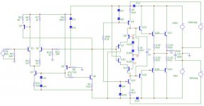
Does anyone have any pcb of a good 5-band tone control?
- By fabiomaster
- Analog Line Level
- 18 Replies
Does any forum member have any project and pcb of a 5-band tone control that doesn't have a built-in preamp and that's stereo that you can share? frequency ranges from 50hz to 16khz?
Paralleling LM3886 output resistor question
Hi all, it’s been awhile since I posted, so if I’ve missed something or a pertinent thread I apologize. Anyhow, I got myself some 4 ohm speakers for Christmas and I’ve been using a standard LM3886 amp with a single chip for my 8 ohm but I’m planning on building an amp with two LM3886 paralleled per channel. I’m using the example parallel circuit in the LM4780 datasheet, and on the output it shows a 0.1 ohm 3W resistor on both chips. I understand it’s purpose there, but it doesn’t seem like 3W is enough for such a low impedance resistor on the output. Am I missing something?
Attachments
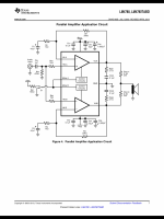
Yet Another Adcom GFA-545-II Restored
- By The Prof
- Solid State
- 39 Replies
Many of us somewhat long in the tooth and who display our gray hairs with pride recall the fondness with which Adcom amplifiers were treated long back. Many of the early amps had the signature of master designer Mr Nelson Pass in their DNA and quite a few models were hot favourites with those who cared for good sound and the ability to drive a variety of speakers well. Recently, after a huge gap of decades, again Adcom gear is finding favour with many and I too acquired a GFA-545-II. Though in non-working condition, I was hopeful of restoring it as a lot of help was available online.
The usual cleaning up of the PCBs, replacement of the electrolytics, checking/replacement of critical components etc breathed new life into it. But the previous owner/service man had tried many things and the amp was not behaving normally. I acquired a copy of the service manual and set out to systematically restore the amp. Soon another 545, in a somewhat worse condition, was acquired with thoughts of cannibalizing stuff for the better of the two. This soon resulted in a working amplifier, but one that had some erratic behaviour.
I had noticed thread where seasoned and experienced Adcom masters were tackling issues with the GFA-565 and posted an SOS there. The resulting exchange is posted here as a new thread. I am also requesting the Admins to delete all the 545-related posts from the 565 thread to do away with the 'thread pollution'.
The posts started with Post #395 on Page 20 on the thread:
https://www.diyaudio.com/community/threads/yet-another-adcom-gfa-565-thread.286742/ :
In order to benefit others who might want to explore working with the GFA-545-II, I am re-posting the entire discussion here in an orderly (though slightly edited) form. Warm regards and much thanks to the masters for all the help.
WONDOM JAB3+ thump
I have a WONDOM/Sure JAB3+ amp and the demo program causes a thump on the line output when there is no signal every few minutes. It is a double thump. Biphasic?
I created a subwoofer program based off their demo and it does the same thing.
Clicking the mute button does not fix it. Disconnecting the external speaker amp from the JAB3+ does fix it which makes me think the problem is with the JAB3+ not the external amp.
Has anyone else experienced anything similar?
Playing music at really low volume also prevents it.
Old heatsink data
- By Kmet
- Solid State
- 3 Replies
Hi there...
I was trying to make amp based on old magazine article and output transistors are mounted on heatsinks. I do not have actual data of thermal resistance so please help me if any of you have old catalogues. Heatsinks are:
Thermalloy 6430B and 6401B
or supplement:
Wakefield 403K and 410K
I will be very pleased with any information regarding thermal resistance or power/temperature rise graph.
Dubravko
2022 project: ALTEC A5
Hi,
On 1st January I bought a pair of A5/A7....what a way to start the year isn't it?
I had to try once.
No "intellectual" project in mind, they will be in my workshop.
What I bought:
Altec 828 clone with the two vertical slots
Altec 416-8C
JBL 2440 16 (but marketing right, they are 8)
JBL 2404H 8
ARAI 290 wood horn
A box filled od components for Xover, but a mess...
What I ordered:
I'm lazy so I ordered two Jagusk Xover crossed at 600Hz and 8500Hz
What I planned to do:
Make them sing, and working on the clone cabinet.
Made from Okoumé ply in 18mm, but the horn panels are really thin, will brace them.
Adding some damping stuff...
My question guys 🙂
1/In order to have them close as OG (crossover excepted ) I'm wondering if Altec 805 (tar filled) would be a better option than ARAI, less audiophile more indaguts thing?
I've a local opportunity for those, not too much money (gosh people are crazy about those 50s' Altec!!)
BUT is:
is this a good idea?
is there a way to use my 2440?
2/ best damping material for cabinet?
3/ share your thoughts 🙂
Thanks
Enjoy 2022
Attachments
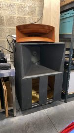
New Issue Email notifications disable doesn't work
- By Elvee
- Forum Problems & Feedback
- 1 Replies
I have unticked both boxes, but I continue to receive email notifications
Why simple crossovers, tuned by ear, don’t work
It seems like almost every day we have a new person asking about online crossover calculators or ready made crossovers.
What we desperately need is a sticky that explains clearly why ready made crossovers don't work, but explained in a way that a person who has no understanding of loudspeaker design understands. Then all we have to do is link to the sticky. I'd do it myself but I think others would do far better job than me.
Anyone up for it?
Primare SPA 23 power problem ...
- By AMaxsplosion
- Solid State
- 1 Replies
Upon turning on my Primare SPA 23, the "Warming Up" light continuously beams but the unit does not complete the warm up sequence so as to be useable.
Is this a fuse problem, I am wondering. If so, how do I fix it. I do not see any repair manuals online. I would be grateful for some guidance.
Is this a fuse problem, I am wondering. If so, how do I fix it. I do not see any repair manuals online. I would be grateful for some guidance.
Pcb layout doubt
- By madhukannan
- Solid State
- 7 Replies
While making a PCB layout should we keep signal, Zobel, and decoupling caps grounds completely isolated? and run separate wires to the power supply ground T ? or is it required to have a connection between them in the PCB?
To which ground the constant current source ground can be combined?

To which ground the constant current source ground can be combined?
6П15П-ЕВ / 6P15P-EV = EL803S / SV83 NOS, NIB (lot of 100pcs)
- By OAA7
- Vendor's Bazaar
- 6 Replies
FS: 6П15П-ЕВ / 6P15P-EV = EL803S / SV83 NOS, NIB (lot of 100pcs)
Hi,
I have in stock excellent special quality electron tubes 6П15П-ЕВ / 6P15P-EV
= EL803S / EL83 / SV83
Index -EB means:
B = tubes of increased mechanical strength and reliability
E = tubes of increased durability (5000 hours or more)
Saratov factory "Reflector"
all the same date codes = Dec. 1976
minimum order = 100 pcs (one box)
price = $200 (i.e. $2 for 1piece)
shipping cost (2500 g)= $30 by airmail
Best regards!
-------------------
Olexandr
Kharkiv, UKRAINE
skype: OAA-1974
Usb microphone for voice and learning
Hi,
I want to build an usb microphone to use on my pc for remote working and podcast recording. If could definitively buy a blue yeti or any streaming microphone but I would not learn much from this.
Where I start from :
-I can solder SMDs, and work wood (and somehow metal)
-I can use kicad and already hade some PCB manufactured for me, but all digital, I come from a software / computer background and don't now much about analog electronic
I've seen this video that seems rather close to what I hade in mind : Building a quality USB-C microphone - YouTube . I have a few questions :
- should I replace the noname usb adc with e.g. a TI PCM2912A or wouldn't it change anything soundwise ?https://www.ti.com/product/PCM2912A
- the video uses a THAT1512 but that5522 or TI INA849 seems to be newer / better SNR version. Any reason not to use them ?
- he uses a jli-2555 capsule. Is there any close quality capsule I could buy from aliexpress (the $13 jil233 will probably cost about $45 once i've paid shipping, vat and custom fees. Buying on aliexpress I can have almost free shipping shipping and pay the VAT directly so I won't have custom fees)
Thank you,
windless
WTB: Riken RMG 33k 2W
Hi there, I am looking for 8-10 pieces Riken RMG 33k 2W resistors. If someone has for sale, please contact me via message. Thank you
Tube Phono PCB - Improved WAD Design
I dub thee 'Tres Phono'! 😎
This is based on the WAD phono stage which is a very well known and excellent sounding phono stage! I improved upon it by using better components and adding a fully-regulated B+ and filament supply. All on a single PCB so all you add is a choke, power transformer and connectors. This went head-to-head with a highly modified EAR and blew it away. Very neutral stage and dead quiet! Also has provisions to add tuning caps to perfectly tune the RIAA points if you have the equipment to do so. PCB designed so parts can be on top or bottom if you want tubes exposed on a chassis. Purchase a PCB and I'll include the schematic and BOM. Part cost was just shy of $300 excluding tubes and chassis parts before the crap hit the fan with component availability.
$35 each shipped to USA. Contact me for international shipping.
Attachments
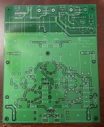
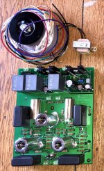
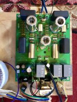
pass x2.5 problem
Hi all ! Summer time in Greece(hot) and my beloved pass pre is refusing to follow the orders I give ,either with push buttons nor with remote. When turned of and let cool down it is back in use. When hot again ,after 5 hours in mains the problem appears again. I opened the lid and by spraying the processor chip(the one mounted in a base) with 'freeze ' spray everything works fine. I guess I need a new chip probably by pass labs . I would like help to get it somehow , thanks !
Greetings to all!
Greetings to all!
relative SPL front and back of a speaker at the baffle step frequency
- Multi-Way
- 61 Replies
At some very low frequency where the wavelength of the sound being reproduced by a closed- back (sealed) loudspeaker system is much greater than the dimensions of the speaker box, the sound pressure level (SPL) measured behind and in front of the speaker system is the same. That is, the difference of SPL readings front and back equals 0 dB. My question is, if frequency is increased to be equal to the baffle step frequency of the speaker system, what then is the difference of SPL readings front and back?
Please don't ask me why I want to know this; I have my reasons which I would rather not bring into the discussion for now anyway. Just think of it as a challenge to your understanding of the acoustics of closed-box loudspeaker systems.
This is a question excluding the open baffle or dipole type of speaker system.
Regards,
Pete
Lowest safe loadline: what is the limit?
- By zintolo
- Tubes / Valves
- 135 Replies
I'm designing a amp to see the limits of a new feedback system, and I would like to know what is the limit you consider on the lowest side for the loadline.
Please consider that the DF has not to be considered here.
The amp is a PP based on a pair of EL34 at 450V B+.
Initial OPT was 6k6 with UL 23%, now I would like to test a 4k with UL 23% I have, but I would avoid to blow a pair of EL34.

The point is that the loadline is on the edge of 2x the max plate dissipation on some points (as highlighted on the image) and this considering a load of 8 Ohm, so it's even worst at mid frequencies where load is usually lower.
What is the limit you consider when you design an amp?
Is that loadline the lowest you'd use, not considering the DF in the equation?
Thank you in advance,
Roberto
Please consider that the DF has not to be considered here.
The amp is a PP based on a pair of EL34 at 450V B+.
Initial OPT was 6k6 with UL 23%, now I would like to test a 4k with UL 23% I have, but I would avoid to blow a pair of EL34.
The point is that the loadline is on the edge of 2x the max plate dissipation on some points (as highlighted on the image) and this considering a load of 8 Ohm, so it's even worst at mid frequencies where load is usually lower.
What is the limit you consider when you design an amp?
Is that loadline the lowest you'd use, not considering the DF in the equation?
Thank you in advance,
Roberto
Attachments
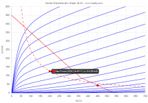
FS: Bang and Olafson B&O ICE1000a Pair
FS: here is a pair of Bang and Olafson icepower 1000a class D amps. These are new and have never been used. Connectors are included.
$165 plus shipping, payment with Paypal friends and family please. Shipping is from Vienna, Austria.
Please feel free to aks any questions. Thanks! -Mac
$165 plus shipping, payment with Paypal friends and family please. Shipping is from Vienna, Austria.
Please feel free to aks any questions. Thanks! -Mac
Microphone Isolation Panel instead of Rear Absorbtion Pads
- By Bradstone
- Room Acoustics & Mods
- 0 Replies
I'm looking into Accoustic treatment for my room, so far I've just put thick blankets over the side walls, nothing spectacular, but for $200AU or so, I could get four sets of these:
https://www.ebay.com.au/itm/12-Pcs-...349624.m46890.l49286&mkrid=705-154756-20017-0
It's enough to spot cover the ceiling, side walls, and a few directly behind the drivers on the fronts.
And I was thinking one of these:
https://www.ebay.com.au/itm/25-7cm-...349624.m46890.l49286&mkrid=705-154756-20017-0
For the rear.
I'm thinking a mild concave shape, slightly angled up perhaps?, it would sit between the two lamps, between me and the clay moulds, this could just remove all of the rear reflections.
My listening seat is a 2m x 2m couch, so no floor reflections 🙂
What do you think? Has anybody tried something like this?
Edit:
So tonight I put some large cushions roughly the size of the array in the place I was going to put the array, and also some makeshift bass traps in the only two available 90° corners in my (assymetric) room.
With some foam bass trap corners It'll be a good $250 purchase I think...
https://www.ebay.com.au/itm/Alpha-2...349624.m46890.l49286&mkrid=705-154756-20017-0
Attachments


Harmony H205/Silvertone 1342 OT
- By eetechTom
- Instruments and Amps
- 17 Replies
Starting my first classic amp restoration and have an output transformer question.The Harmony H205 amp I bought, had the OT replaced with a 16 ohm output sub. It’s a 6V6 pp circuit, rated at 12W I believe?. Haven’t gotten to the point of powering it up yet, but will obviously need a better OT. That orange cap needs to go too
This amp has the original Rola 12”, 3.2 ohm speaker. Any suggestions on a quality OT would be greatly appreciated. Want to do justice to this classic.
This amp has the original Rola 12”, 3.2 ohm speaker. Any suggestions on a quality OT would be greatly appreciated. Want to do justice to this classic.
Attachments
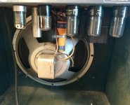
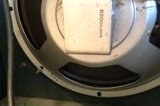

Wanted: SEAS ER18, and DXT tweeter. In usa.
I'd like to make Mark K's ER18/DXT speakers - after putting his RS225/RS28F speakers together and finding out I like the way he did the crossovers.
Let me know if you have a pair of either ER18 or DXT to sell.
Need shipped to CA, 95521.
Thanks, Don
Let me know if you have a pair of either ER18 or DXT to sell.
Need shipped to CA, 95521.
Thanks, Don
FS TWTMC D-TWTMC D&D-Maxwell Supercap
For sale:
1 x TWTMC D Driscoll assembled with SC Cut 11,2896 MHZ Crystal
21/36/15wi.jpg - Visionneuse Zupimages
1 x TWTMC D Driscoll 24,5760 MHZ assembled (no Crystal)
21/36/irk7.jpg - Visionneuse Zupimages
1 x TWTMC D&D Daugther board assembled
21/36/lwhw.jpg - Visionneuse Zupimages
4 x LDOVR 3045-S Regulator 2x3,3 Volts - 2x 6,6 Volts
21/36/owpv.jpg - Visionneuse Zupimages
2x Supercapacitor Maxwell 2000 Farads 2,7 Volts
21/36/ayoj.jpg - Visionneuse Zupimages
Reasonable price to negotiate with the buyer.
Guesstimating transformer power ratings
- By Kay Pirinha
- Power Supplies
- 12 Replies
Hi,
in the past two years I've harvested a bunch of power transformers from some cheesiy sounding and crappy Hammond transistor organs. Sadly, I didn't have a close look at their badges and the power consumption that might have been written there, but anyway, all these organs featured Leslie or Rotosonic units whose motors are of unknown power consumption as well.
The 1st pic shows a pair of identical trannies, Hammond part # 003-054471, coming from a Collonnade and a - smaller - Aurora Classic. Their lamination stacks measure 105 x 87 x 55 mm (4 1/8 x 3½ x 2 1/4 "):

Next one is the tranny of a notably bigger Concorde. Part # 003-046819. Lamination outline is the same, but stack height is a bit lower: 105 x 87 x 50 mm (4 1/8 x 3½ x 2 "):

Next one came form a Model 8022 organ. Part # 003-048011. Laminations measure 95 x 80 x 50 mm (3 3/4 x 3 1/8 x 2 "):

The next pair also was in the Colonnade and Aurora organs. Their primaries are 115 Vac, secondary is 14 Vac. Perhaps they might serve in a BTL pair (2 x 2) of amplifiers. Part # 003-054853, laminations are 76 x 63 x 41 mm (3 x 2 1/2 x 1 5/8 "):

The smallest one. Part # 003-046374, laminations are 66 x 56 x 26 mm (2 5/8 x 2 3/16 x 1 "):

Finally a 117 Vac power tranny that came from a Leslie 121 multi channel amplifier. It powered four almost identical amplifiers, consisting of a 12AU7 and a pair of fix biased 7189's each. This is the one I was referring to in my proper winding technique thread. I'm planning to rewind it as an OT of about 40 W power. Laminations are 114 x 95 x 33 mm (4½ x 3 3/4 x 1 1/4 "):

Which power capabilities can I expect from these transformers?
Best regards!
in the past two years I've harvested a bunch of power transformers from some cheesiy sounding and crappy Hammond transistor organs. Sadly, I didn't have a close look at their badges and the power consumption that might have been written there, but anyway, all these organs featured Leslie or Rotosonic units whose motors are of unknown power consumption as well.
The 1st pic shows a pair of identical trannies, Hammond part # 003-054471, coming from a Collonnade and a - smaller - Aurora Classic. Their lamination stacks measure 105 x 87 x 55 mm (4 1/8 x 3½ x 2 1/4 "):
Next one is the tranny of a notably bigger Concorde. Part # 003-046819. Lamination outline is the same, but stack height is a bit lower: 105 x 87 x 50 mm (4 1/8 x 3½ x 2 "):
Next one came form a Model 8022 organ. Part # 003-048011. Laminations measure 95 x 80 x 50 mm (3 3/4 x 3 1/8 x 2 "):
The next pair also was in the Colonnade and Aurora organs. Their primaries are 115 Vac, secondary is 14 Vac. Perhaps they might serve in a BTL pair (2 x 2) of amplifiers. Part # 003-054853, laminations are 76 x 63 x 41 mm (3 x 2 1/2 x 1 5/8 "):
The smallest one. Part # 003-046374, laminations are 66 x 56 x 26 mm (2 5/8 x 2 3/16 x 1 "):
Finally a 117 Vac power tranny that came from a Leslie 121 multi channel amplifier. It powered four almost identical amplifiers, consisting of a 12AU7 and a pair of fix biased 7189's each. This is the one I was referring to in my proper winding technique thread. I'm planning to rewind it as an OT of about 40 W power. Laminations are 114 x 95 x 33 mm (4½ x 3 3/4 x 1 1/4 "):
Which power capabilities can I expect from these transformers?
Best regards!
-
Poll
Which DIY speaker for metal/rock (newer, well-produced)
Which DIY speaker would be better for newer, well-produced metal/rock (Periphery, Jinjer, Born of Osiris, Sevendust etc), the PE Amiga or DIYSG Helix Dome TM? The lows below 50hz will be crossed to a sealed HSU sub.
Help with Audiolab 8000a Mk1 information
- By Kaibosher
- Solid State
- 22 Replies
Hi all!
Long time scroller, first time poster here.
I flippin love this forum - general thanks to all involved.
So: I got a cheap Audiolab 8000a on feebay.
Serial number is faded but looks like 667038.
It has Din sockets, and AFN8411 outputs - Early version.
Right channel has had magic fairy smoke escape predrivers, and some resistors.
I have not had a proper dig around yet, but seems to be a common problem.
Questions:
Any thoughts and opinions about the amp are welcome.
Thanks!
Long time scroller, first time poster here.
I flippin love this forum - general thanks to all involved.
So: I got a cheap Audiolab 8000a on feebay.
Serial number is faded but looks like 667038.
It has Din sockets, and AFN8411 outputs - Early version.
Right channel has had magic fairy smoke escape predrivers, and some resistors.
I have not had a proper dig around yet, but seems to be a common problem.
Questions:
- Does any kind (or not) soul have a Mk1 service manual?
- Anyone know anything about the AFN8411 mosfets? Very little info out there regarding replacements.
- Has anyone replaced blown predrivers / drivers / outputs on this model with new or available devices.
Any thoughts and opinions about the amp are welcome.
Thanks!
Bipolar coupling caps
- By emosms
- Analog Line Level
- 3 Replies
Could there be any harm using these?
Any benefit over polarised?
I guess, there might be a benefit, if i try to maintain high signal level voltage in the system (bipolar psu opamps)
Here is the curcuit (attached).
What if I keep only the input caps (the digipot input)?
Would the shunt resistors at the opamp input/ output make problems if there is a dc offset and dc coupling (without coupling caps10uf)
I mean, the dc offset would cause small constant current through the 68k(input) and 10k(output).
Would that cause noise or make the digipot distort (dc coupled,loaded with 68k)?
Not sure if the digipot(some cmos matrix) coul have a dc offset
Attachments
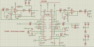
Power amp PCB layout - GND pour on both sides?
- By tristanc
- Construction Tips
- 0 Replies
I've been working on a Baby Huey stereo pcb. Everything on one board just like Pete Millett's DCPP: https://www.diyaudio.com/community/threads/el34-baby-huey-amplifier.326920/page-68#post-6891898
Should I have a GND copper pour on both sides?
Pete has only top. I can see that having two pours could cause further ground loops, but there are a couple of 'islands' that aren't as connected as I'd like. Might not make any difference though.
I'd appreciate if someone more knowledgable in PCB layout could take a look and check for any howlers. I'm sure there are improvements to be made, but I think 'done' is better than 'perfect'.
Images and schematic attached.
Interactive view here: https://www.tristancollins.me/diyaudio/ibom.html <- probably easier to see the traces
Source files here: https://github.com/tristancollins/HiFi-BabyHuey
Thanks,
Tristan
Attachments
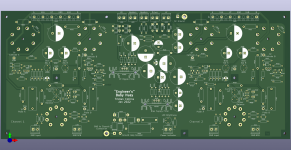

Help! Is it the power supply, or something else?
- By AdrianEnache
- Headphone Systems
- 3 Replies
Hy
I'm probably silly but I'm trying to make it work.
I have a small headphone amplifier that requires +12v ground - 12v.
I have 3 power supply's without the ground connection. (just + -)
If I conect it like this, (just + -), it doesn't work. If I mess around with - on the ground for a sec, I have sound (poor sound).
Taking a separate wire to the wall outlet (ground) doesn't help.
I am afraid that I will try stupider and stupider things until I break it.
Help...(I am also a nuby, just to make things clear).
Thank you!
Recommended driver for line array?
- By samsagaz
- Full Range
- 36 Replies
Hi, im interested in purchase some drivers (50 pcs) to build some line array as front speakers of my HT .
What driver/model recommend me to purchase? Maybe some TC9s,
Was thinking about to use this FaitalPRO 4FE35 4" Professional Full-Range Woofer 8 Ohm will works as line array?
What driver/model recommend me to purchase? Maybe some TC9s,
Was thinking about to use this FaitalPRO 4FE35 4" Professional Full-Range Woofer 8 Ohm will works as line array?
Goldentone single valve guitar amp troubleshoot
- By Yellow Cab
- Instruments and Amps
- 40 Replies
HI this is my first post as a newb here so hoping Ive landed this in the right place
From time to time I've DIY racked and fixed old pre amps, tube pre amps etc but only at a pretty basic level (eg cap replacement, basic signal tracing etc) and not where I would be taking any chances with the circuit beyond what I know. Also very aware of the dangers with high voltage here.
Been reading up on tube operaton and my physics is not great but understand the basic concepts to a point…
I’m just troubleshooting what I initially thought was a bad connection in my single valve (6gw8) Goldentone guitar amp ( Aussie practice amp from the 60’s). Attached is a link to a schematic (with thanks to J Mumford and C Lilly) that is pretty much identical to my amp except for one or two resistor values.
https://www.ozvalveamps.org/electravox/60s electravox single valve amp-p-jm.jpg
I think a good chance I’m dealing with a bad tube but I have swapped out another tube and both show identical symptoms. Before I go searching for another 6gw8 I was wondering if it could be a different problem eg.bias /voltage/ ac ripple?
Symptoms as follows….
Initially signal faded and disappeared after a certain amount of playing but was an intermittent thing..
Was able to bring it back temporarily and intermittently by addressing contact/ solder at tube pins but now the output is consistently weak have tensioned socket etc to no avail.
The triode stage appears to be amplifying as it should and a good signal goes in to the grid post volume and tone pot at the pentode stage but comes out weak and distorted at the anode (which makes me think either something wrong internally with the tube or some issue with voltage /current/ bias?)
Attached are some photos on my old oscilloscope showing a 440hz sine wave coming in and at the final stage before it hits the output transformer.
I took some voltage measurements at key points in reference to the schematic as well….
Voltage at triode plate (C) is 147vdc (schematic indicates 82vdc ) stock resistor from point B to C on my amp is 100k (not the recommended 220k)
Screen Voltage at Point (B ) is 260vdc (recommended is 250vdc)
Plate voltage at pentode (A) is 320vdc (as opposed to recommended 309vdc )
Heater voltage is 7.02 v ac (measured from pin 4 to 5) recommended is 6.2 vac
Btw I did see some ac on the (A) voltage but not a huge amount
Original caps replaced a few years ago
Scope pics attached and finally a picture of the tube glow if that helps : )
Just thought this might be a classic indication of either bad tube or another common symptom ? Not sure… if anyone has the time to share expertise on this that’d be really appreciated!
Thanks
Tim
Attachments
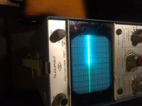

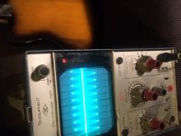
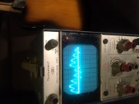
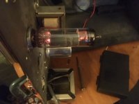
Load more
Projects by fanatics, for fanatics
Get answers and advice for everyone wanting to learn the art of audio.
Join the Community
507,807
Members
7,889,131
Messages