what are the options out there for sealed full range bookshelf speaker designs?

are there plans out there for shallow, full range, sealed bookshelf speakers?

or am I hoping for something that is currently unobtanium?

I'm looking for something to hang on the walls of my small bedroom. I'm not sure what this room was before the reno that closed in the carport and added many more rooms to the basement, but was 9' wide and 11' long before the added a 3' x 6' closed closet in one corner, so I have next to no room for anything beyond mt twin bed, dresser and chair to sit n listen to my headphones in. listening to then would be when lying down reading n winding down for the day.

also some back story on me to help you understand why I will likely be infuriating at some point while being totally unintentional.

I'm not sure how weird this is, but due to injuries survived almost 25 years ago my brain no longer works like most. I share this as I need to start at the very end and work myself back to the beginning to learn something. this can be frustrating for many helping me as it essentially means I need to be told exactly what I need for a solution and then experience the rule's / law's that need to be understood and worked with to be successful. it's frustrating for me because thus inevitably makes learning something take longer than usual. it's also a pain in the *** because I'm financially of smaller means. not destitute, no debt, but still living check to check.

yes, it does mean that project will be more expensive than it needs to be, but that is the curse I live with after crashing my mountain bike while bombing down a hill and crashing at 45mph. I remember nothing of it, only what I must cope with and overcome since I regained consciousness 2 weeks later.

lastly I'm clumsy n have hands full if thumbs...but fortunately have a patient son in law who is clumsy, but very capable hands that take joy working with wood.

oh, I'm 43, smart yet stupid, live in Canuckistan and pleased to meet you all! 😀
  • Like
Reactions: A Jedi

Balanced Attentuation / U-Pad

Hi all,

I need some attentuation between my MiniDSP 10x10 and 3eAudio TPA3251 (4 channel) amp. The MiniDSP is very noisy and the drivers in my active setup are sensitive (10" pro driver and compression driver). I have my MiniDSP going balanced straight in to the TPA chip bypassing the onboard op-amps. MiniDSP is fed by SPDIF. The amp is dead quiet.

The MiniDSP input gains are down 18db, I have a 10db L-pad on my compression drivers and yet I still have my windows volume level hovering between 10%-30%. Something must give.

I would like to put some passive attenution on the balanced line betwen MiniDSP and amp and having read everything I could find here would someone mind looking over my sums, please?

MiniDSP output = 560 ohms
10db attenuation K factor = 3.16
Rshunt = 560ohms
Rseries = 560 * (K-1) 2.16 = 1209 ohms
Rseries/2 = 604.5 ohms

upad.JPG


R1/2 ≈ 600 ohms
R2 = 560 ohms


I plan on using 1w metal film resistors.

Cheers! 🙂

DC on the speaker outs?

Maybe someone can help me out here. I've been building my Icepower amp, https://www.diyaudio.com/community/threads/why-do-i-have-56v-on-my-vdrive.383620/latest and things have been going pretty good. I've got it up and running but I noticed today that while I was watching a video on youtube that was all dialog so the woofers where hardly moving, that from time to time the woofer cone would either push out or pull back in unrelated to the video. It did this kind of slow and didn't make any noise but it is acting like a speaker does when you put a 9 volt battery to it'd terminals it either goes in or out so I am assuming it has to be DC that is getting to the speaker. Does anyone know what might be causing this to happen? All of the specs for the amp are at the link above on the other thread if you need to know. It has me concerned because I know it shouldn't be doing that. Any help with this would be greatly appreciated.

My first Tannoy Autograph

It was love at first sight :hbeat:

When I first saw the Autograph's enclosure at http://users.bigpond.com/tunnelgap/Tannoy/autograph.html

it really made my juices flow. Then, when I began to understand the principle behind (and before) them, I simply was captivated. I had to make them mine!

And now I built my first Autograph:


An externally hosted image should be here but it was not working when we last tested it.

Parasound A52 popping noise when idle

I've been trying to identify the source of a popping noise in one channel when the amp is idle. It appears to be mostly positive excursions that last around 1ms or less and are about 1V on an unloaded output. The amp has a jfet input using 2SK170/2SJ74 put those are difficult to find so I have not swapped them out. I've replaced the 2SC2240 and 2SA970 in the differential pair with KSC1845 / KSA992 and the issue continues.

Power rails seem ok and I've tested the caps on the differential section which is regulated. I believe that it is either heat or voltage related as the issue happens more often as the rails approach the 60v limit of my bench supply and it almost never happens in the first few seconds after applying power.

The amp is direct coupled so it is more difficult to isolate the stage that is causing this. I'm hoping to get some suggestions to track it down.

Behringer Ultra-Linear measurement microphone and MXL Mic Mate

Used once, years ago....
Gathering dust.
ECM8000 with has, mic stand mount and wind blocker.
Comes with MXL Mic Mate XLR to USB adapter.
Located in Kitchener ON
$75 shipped

https://www.avshop.ca/recording-audio-interfaces/mxl-mic-mate-classic-xlr-to-usb-adapter

https://cosmomusic.ca/products/behringer-ultra-linear-measurement-condenser-mic
20220320_120742.jpg

Attachments

  • 20220320_120656.jpg
    20220320_120656.jpg
    294.9 KB · Views: 83
  • 20220320_120733.jpg
    20220320_120733.jpg
    241.4 KB · Views: 84
  • 20220320_120718.jpg
    20220320_120718.jpg
    386.2 KB · Views: 93
  • 20220320_120702.jpg
    20220320_120702.jpg
    527.7 KB · Views: 114

diBirama driver measurements

Just found this nice collection of driver measurements:

http://www.dibirama.altervista.org/le-prove.html
What I've found challenging with regards to driver measurements on the web is that measuring conditions are never the same, which makes it hard to do reasonable comparisons.
Here however, we have a huge collection of measurements all presumably done under the same conditions.

Looking through a large portion of the measurements, what stood out to me is how clean of a waterfall some metal cone drivers provide (up to breakup of course).
But despite this there seems to be a general preference of paper cone drivers in the industry.
Buchardt even changed from aluminum to paper cones in their latest speaker iterations.

Modification of typical Chinese preamps or fully DIY?

Hey all,

some of this may have already been discussed, so apologies if this is the case and please just point me to the rejects discussion thread:

I’m in need for a decent tube preamp. Unfortunately my taste for music is very wide, ranging from classical to metal and anything in between, and I’m aware that some tube designs may lead them better for done music than for other music styles. Fortunately, if going the diy or Chinese modified stuff route, that should be cheaper than buying brand new well establish stuff.

My immediate thought goes to buying one of those 12ax7 12au7 units, also sometimes referred to as marantz 7 clones. They’re affordable and relatively easy to modify.

Other options include:
https://a.aliexpress.com/_mOTfK6M , which seems to be a triode based design, and could be a decware clone.


https://a.aliexpress.com/_mOTjWjO , which I’m completely unfamiliar with.


https://a.aliexpress.com/_msm2w3e , another one that has my interest.

I’m aware that some people consider these rather inferior, but as I’ve never build a tube amp before, and don’t have the skills to design one, I’m looking for some advice on what my options are.

Chinese stuff and play around with upgrades, or full diy?

thanks!

New project: 3way 22W/4851, MW16TX-8, T25B in WG

Long time ago I started this project, originaly with R2004 and MW16P, but after working on another projects and experience with T25B without WG, I decided to revive this project and update drivers to textreme and Be Bliesma.
I plan LR2 between woofer and mid at around 300Hz, and LR4 at ~2200Hz between mid and tweeter.
From already available measurements of TX from hificompass, and my measurements of T34B in larger WG, I have really high hopes in this driver combo and expect superb results, both measured and sonically. TX and T25B should be good sonic match but I am little bit afraid of Scan Speak and Satori combination, as I had already troubles to match 28W and MW19P. Ok, one never knows until it is tried and listened to.
Measurements will come soon, tweeter mounting adaptors are in progress.
So for now, at least some images of drivers in the cabinets.

Attachments

  • 20210429_171911.jpg
    20210429_171911.jpg
    243.8 KB · Views: 1,314
  • 20210429_171930.jpg
    20210429_171930.jpg
    248.5 KB · Views: 1,348
  • Like
Reactions: IamJF

Newbie to DIY audio, looking for a class-A, single-ended MOSFET power amplifier schematic.

Title mostly says it all. I am completely new as far as DIY audio is concerned, but I know my way around a soldering iron and can print my own PCBs. I am looking for a schematic for a great-sounding, class-A, single-ended MOSFET power amp, with preferably as few components as possible. Hope that someone here can help!

Peerless TC-9 WMMMMW + T beside or WMMTMMW

Hello,

After reading so much about this little driver did pull the trigger on 8 of them.


Goal is to build a WMMTMMW or WMMMMW + T beside configuration.

Bass would be SB20 with active filtering, drivers aligned for 90DB. No external sub.

Crossover W-M would be 160 to 200Hz


And crossover M-T could be:

around 2000Hz if MMTMM
around 4000Hz if MMMM and T beside, due to closer mid drivers (wanting to avoid comb filtering)


Side tweeter looks more appealing because 4000Hz gives more choice, and leaves a wide range to the TC9 for a more coherent sound

What would be the impact on imaging of not having the tweeter on same axis as other drivers ?


My experience so far is WAW (crossed between 80 and 160 depending on projects), mostly with Jordans.

Tweeter not selected yet, will depend on configuration.

Thanks for advise!
François


BTW did already simulate and all excursions are fine even at higher SPL than needed (measuring 85DB at 3 meters when watching rock concerts)

Event Studio Monitor Problem - Please HELP!

Hi all,

I currently have a pair of Event TR-6 bi-amped monitors and I am having a problem with one of them. As soon as I power the unit on, I hear a loud fuzz/static sound coming from both speakers. It does appear that the fuzz is louder from the tweeter, but that could be due to the nature of the fuzz (i.e. not much low freq. stuff).

When I run an audio signal to the unit at a normal level, if I listen closely (head next to speaker), I can barely hear the audio underneath the fuzz. It seems like it would be something in the signal path before the speakers and possibly before the amps.

I have tried swapping power and signal cables with the working unit, but it did not change anything.

One possible thing that may have caused this is electrostatic discharge. I noticed this problem for the first time after I felt a shock when I pushed on the power button. :Ohno:

Unfortunately, this problem started right after my warranty had expired. I know I could send the unit in for repair, but I fear that the cost of shipping plus the actual repair combined would be close to that of a new unit. That is why I would like to know if there is anything that I can do to repair the unit myself? I do have some background in electronics, so I would be comfortable if you could give me a starting point or have any ideas of what could be wrong based on experience.

I have contacted Event and they gave me the schematic (attached), but had no ideas for what could be wrong.

Thanks in advance for the help, I would love to get back to making music!

Please let me know if you have any questions for me.

Thanks again 🙂

50 pieces Siemens D3a 7721

Good day,

A long time ago I bought 60 pieces of the D3a 7721. The idea was to use them in a phono (RIAA) amplifier, and have more than enough spares, but I do not think this will ever happen. So I am putting 50 pieces of the them up for sale, the whole lot for 1250 Euros. Is that doable?

best regards, Erik

Attachments

  • 2022-03-17 12.02.17.jpg
    2022-03-17 12.02.17.jpg
    431.4 KB · Views: 126
  • 2022-03-17 12.02.25.jpg
    2022-03-17 12.02.25.jpg
    471.1 KB · Views: 129

Modular TDA1387 development

Hello,

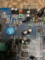
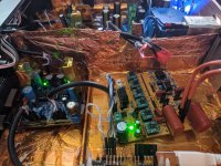
Here is the V2 of my modular TDA1387 DAC, but even this one i dont consider released but a development version which is why im making this thread.
I'll then release the gerber files and anyone can make their own if they want to.

1647366571728.jpeg

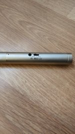
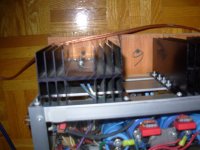
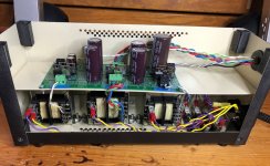
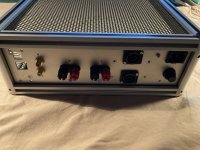
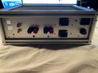
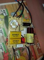
We're using PSU -> cap multiplier -> Jung superreg. For I2S, we have the JLsounds I2SoverUSB board.

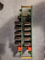
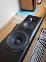
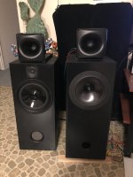
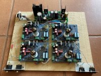
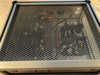
Using 5 x 6 dacs in parallel in little towers, parallelisation averages the currents and improves SNR, but more importantly increases current, meaning we can get away with using a lower value passive resistor, The dac wants to see as close to 0R on its outputs. Also, we dont need further voltage amplification to line level, here i used a 51 ohm resistor.
There's footprints for pin 7 (VREF) decoupling caps but i dont hear a positive difference and some others practice this same method.

Im still troubleshooting some parts though, as simple as everything is i managed to muck it up apparently.
With 30 dacs, current is +-30mA. On 51R that should be almost 1.5v p-p, however on full volume i only get 30mA (what we should get with only one dac). So somehow we managed to break ohm's law here.

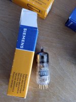
I also tried TDA1543 (non A, that one is EIAJ) since they are pin compatible and appear both are I2S. I have some NXP branded ones, but they dont seem to work at all, just get some white noise (although its volume changes slightly with what should be music playing, but its still pure white noise). I tried a lot of combinations according to the connection sheet like left and right justified and different word lengths, but all is the same, so i dont know if anyone else has experience with this..

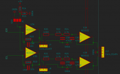
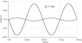
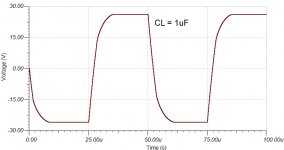
The opamp I/V (passive and opamp I/V is switchable via jumper, for evaluation) also seems to have an inexplicable 1.75V of DC offset and sounds crunchy.
J5 selects what gets connected to the non inverting output. When used with +-15V (like i do), i connect it with GND. The other is just VCC/2 for single supplies.
The feedback resistor is low because there should be a lot of current so we dont need a lot of gain, after that there's the optional buffer (connect 3 and 2 on J7 and J8). Anyway problem happens before the buffer so it doesnt seem to be the issue. Its probably something really silly but i dont see it..

1647366554331.png


Best regards

Attachments

  • 1647350576535.jpeg
    1647350576535.jpeg
    290.6 KB · Views: 110
  • 1647351507735.png
    1647351507735.png
    15.8 KB · Views: 105

DIYer with a goal

Hey everyone, I am just a guy who has loved listening to music since a kid. I have a goal of assembling a system from component parts from a tried and proven design used by the community here which may sound as good as something several times it's price that I wouldn't be able to afford otherwise, whilst also be proud of building it and enjoy the process of doing so. Who knows, maybe it will turn out a hobby? I have dabbled into this idea a bit and even gotten intimidated because I can only describe myself as a guy who is a complete beginner but wants to DIY something that would rival a flagship system in a renowned Hifi gear maker's showroom. Anyone who has been there done that or wants to point me where to begin?

CS8416 does not sync on external clock

Hello, I have build a CS8416/CS4397 DAC configuration in hardware mode. This is working fine.

My next step was to ad an external clock so i connected a 33mhz clock to omck that is routed to the clock to rmck (at no spdif input). So far so good.

But when i apply an SPDIF signal, the LRCK wont lock on the 33Mhz clock but does fall back to the SPDIF/PLL clock. 🤔

My best guess is that i also have to toggle the HW/SW mode of the CS8416 OR to set a register to "use" the external clock instead of the SPDIF regenerated clock.

So, how can i get the CS8416 (which is in HW mode), that it will use the external 33Mhz clock to lock the LRCK.

I like to use the external clock in CS8416 hardware mode. Can it be done?

LM3886 Composite amplifier - how accurate are simulated results ?

Hello all,

I have been following the composite amplifier topic on this forum for a long time and was able to gather many a thing from the experiences of other members. Naturally, I then started trying LM3886 / LME49710 simulations of my own, based on the following starting points that I was able to gather from various threads on this forum.

  • The LM3886 needs to be operated in a closed-loop manner, for "more predictable clipping behaviour", and most of the amplification needs to come from the high performance op-amp and not the power-amp chip.
  • Many power-amps are designed for a minimum gain (10 for 3886) and therefore their gains need to be reduced without affecting stability.
  • Since LME49710 obtains only a limited voltage swing of 15-16V, the LM3886 needs to be operated at a gain of 2-3V/V, for the typical home / studio amplifier.
  • In order to obtain any significant improvement in performance, the composite audio-band loop-gain needs to be at least 100x (+40dB higher) than that of the power-amp.
  • The composite amplifier needs to remain stable even when presented with a highly capacitive load (e.g. 4.7uF) that emulates the capacitance of typical speaker cables.
  • The capacitor across the inputs of the LM3886 is necessary for large signal stability, clipping recovery and noise/EMI suppression.
  • The compensation capacitor should not be a critical circuit component, but only a means to fine-tune the transient performance of the system.
  • In order to maintain a high excess loop-gain, the net amplifier gain needs to be minimal, e.g. 10V/V (20dB) for a typical domestic application.
  • For a stable composite amplifier, the op-amp cannot be faster than the power-amp.

However, lately I happened to find that TINA-TI does not show proper results for the open-loop responses of many parts, possibly due to DC offset saturation. Consequently, my amplifier circuit has not been able to make it to reality, as I am unable to confirm the accuracy of the simulation results (attached).

Though the simulations look good, how accurate are the National / TI models and how far are these from reality? Since this is the first time I'm using TINA (I used PSPICE for over 15 years), I would like to know some of your experiences with this topic.

Looking forward to your comments,
Thanks.

Attachments

  • Response.jpg
    Response.jpg
    118.4 KB · Views: 201
  • 20k Sinewave.jpg
    20k Sinewave.jpg
    52.3 KB · Views: 181
  • 20k Square wave.jpg
    20k Square wave.jpg
    41.6 KB · Views: 160
  • Large step.jpg
    Large step.jpg
    46.5 KB · Views: 148
  • Small step.jpg
    Small step.jpg
    65.3 KB · Views: 162
  • Without.jpg
    Without.jpg
    121.7 KB · Views: 167

Opinions Sought, Help Me Decide

Which woofer to use crossing to Pyle PDS442/Dayton H70E in a two way. Michael Chua's (Ampslab) review of that combo.
https://ampslab.com/blog/2018/04/12/pyle-pds442/
I realize the Pyle would have to be padded down a lot to work with either one.
I have two 8" woofers at my disposal Visaton W200S-8 and Dayton RS225-8
https://www.visaton.de/en/products/drivers/woofers/w-200-s-8-ohm
https://www.parts-express.com/pedocs/specs/295-356--rs225-8-spec-sheet.pdf
I've built two cabs, both BR, one 32 liters and the other 42 liters.
Here's a pic of the cabs.
I would re-do the one on the left to eliminate the tweeter and move closer to the horn.
If anyone has any suggestions regarding XO that would be great.
Thanks for any and all suggestions.

tubav

Attachments

  • IMG_0310.jpg
    IMG_0310.jpg
    403.5 KB · Views: 102

For Sale Bits and Bobs

Hi All,

A few bits for sale:

1) Furutech FI-1363 UK plug

"This item is made to exacting standards and fully CE approved, audiophile grade.

Featuring copper contact pins and cryo treated and de-magnetized using Furutech''s patented Alpha process which removes internal stresses from within the material and helps to improve conductivity as a result.

The plug can accept a wide variety of cables of varying diameters up to 15mm and beyond. The plug is perfect for DIY as it has a patented cable clamping system which is very easy to adjust"

Used for around 3-5 hours, then taken off to repurpose the cable it was on.

As good as new, £50 delivered UK

https://uploads.tapatalk-cdn.com/20220314/59f2a49cb6f160829f6f2e396a95f4b3.jpg

https://uploads.tapatalk-cdn.com/20220314/308bd242cc93073168d6adad8e9ef625.jpg

https://uploads.tapatalk-cdn.com/20220314/7165f18547d27f8614815e16986780e3.jpg


2) 20K TKD 2CP-2511 Dual, Stereo Potentiometer.

"The TKD (Ko-on) potentiometer is highly regarded, probably one of the best pots in current manufacture, as used by Audio Note. Please note this is not your standard taper potentiometer but is a shunt attenuator/taper type to give you better performance than your standard taper potentiometer."

This pot is a massive step up from the Alps Blue that seems to populate so much gear. Genuinely resolving, Excellent accuracy of tone and has a really honest sound. I was genuinely impressed with it in the Prototype BT2. No longer required, solder once and now removed. Used for 8-10 hours max.

This cost me around £100, so £75 delivered UK seems fair.

https://uploads.tapatalk-cdn.com/20220314/323d6f2950f95770c651dac9122fbf0b.jpg

How to add an amplifier selector switch to my GG preamp?

I run a nicely modded Trabscendent Sound GG preamp that I built. It currently only have one set of outputs, and I'd like to add another set, along with a selector switch that will allow me to choose between the 2 amps (to allow me to use the same front end with different amps driving different speakers) or to run the 2 amps at the same time (to biamp one set of speakers). I haven't yet decided on whehter the 2nd amp with be tube or SS, but my main amp is a Finale Audio EL84 SE design.

I need help knowing what type of switch I would need (I assume it'll be a 3 position toggle with the center position sending the signal to both amps), and what the wiring schematic would be. A picture of the internals of the GG is attached. There is a lot of room to work inside the chassis, as well as a lot of room on the back panel to add a toggle and another set of RCA outs. I am not at all concerned with drilling holes in the back panel.

I just want to make sure I do this right, and I'm not sure what the potential pitfalls will be. I would appreciate any help!

GG5.jpg

Kick@#! winged OBs for pick up in Ontario

Edit: the offer is: you pay Parts Express price for the 15inch Definimax drivers (they are just broken in) and you can have the OBs for FREE!!

As much as it pains me, my GREAT sounding OBs got finally kicked out for their low WAF: so before I cannibalize them to reuse the drivers, I thought I would check for a few months if there is someone out there that wants them. The baffles were made by a carpenter, solid mahogany trim all around and veneered baltic birch (mahogany on the front and walnut on the back). The 15inch bass driver is mounted by the magnet (to take the weight and the vibration off the baffle); that was a feat in itself. I can tell you how they were actively XOvered in my application. I would prefer to sell the Visaton B200s and keep the AL200s to repurpose them.

They are in Windsor (ON), across from Detroit, MI.

You can see them at these links.

https://www.diyaudio.com/community/threads/ultimate-open-baffle-gallery.123512/page-130#post-5670164

and what they looked like before:

https://www.diyaudio.com/community/threads/are-you-active-multi-way.266524/page-3#post-4158184

https://www.diyaudio.com/community/threads/ultimate-open-baffle-gallery.123512/page-112#post-4970383

Dual mono F5 First Watt Pass clone copy diy 25 wpc Class A 40 watts 4 Ohms power amp

SOLD SOLD SOLD
Dual mono version of F5 First Watt power amplifier
Pass clone copy diy -
amp is 8 Ohms 25 wpc Class A
and 40 watts 4 Ohms

Used as a power amp with a multiple of different types of speakers
- amp played very well with 6 ohm floor-standers!

The final image is before my friends made and fitted for me the face-plate.

It does not run overly hot for Class A, as case has side vents and four [one each transistor] very large heatsinks.
J-fet and Mos-fet in construction.
Amp has board for speaker protection.
Zebrano real wood veneer-to-ply faceplate, with a perspex top.
{Metal front plate avail. thru' CAM, but not supplied}

All parts used are of good quality
F5 is a two Plitron [now Noratel] power transfo amp and very quiet in operation (only noise will be your source and pre-).
Amp is like two power amps in one case, each side has its separate board/ pcb.
It has 96k EACH SIDE m-f of main caps = 192k m-f in total - an unreal amount!
Amp will deal with 2-3 Ohm loads as it delivers sufficient current when needed.

To make one like this amp would cost 550-600$ in parts alone.
Sound is really very good, the like of which you will not get for less than 1,500 dollars. Fact.

Want to hear it? You can have an audition.
Seriously interested, I'll seek to weigh it - 17x7x13 inches at approx. 30+ lbs.

Price is firm at 725$ CAD - incl. Canada shipping;
NO TIMEWASTERS, Please

I can ship it FROM EAST PART OF CANADA, but it's heavy;
USA Buyers need to pay extra 75$ CAD for shipping. ie 800CAD$ in total.

EMT preferred, but F and F on Paypal is possible.

Attachments

  • DSCN2123.JPG
    DSCN2123.JPG
    443.8 KB · Views: 418
  • IMG_3376.JPG
    IMG_3376.JPG
    88.9 KB · Views: 405
  • DSCN3127.JPG
    DSCN3127.JPG
    305.3 KB · Views: 399
  • DSCN3126.JPG
    DSCN3126.JPG
    242.9 KB · Views: 396
  • IMG_3382.JPG
    IMG_3382.JPG
    80.9 KB · Views: 398

Cheap router, worth it?

Hello, welcome to my first post on this website.

I'm contemplating my first real DIY speakers, and it seems like a router is a good thing to have for this. Otherwise I will be cutting my holes with a jigsaw. However, I'm somewhat hesitant to just buy a Porter-Cable or something, when there's a chance it won't really get used again. I currently don't have room for a router table, either.

So I've seen some cheap routers. Are they usable for non-heavy work, like the cutting involved in making speakers (cutting holes and insets, possibly rounding edges)? The ones I've seen specifically are:

Ryobi R161K, $59 (1.5 hp)
Craftsman 17504, $49 (1.5 hp)
Craftsman 17574, $59 (1.5 hp)
Skil 1823, $63 (1.5 hp)
Chicago Electric 1hp/$39, 1.75hp/$60

Another option is to use a router base on my rotary tool, but I'm unsure how suitable this would be, and I can't seem to find the router attachment for the RTX tool anyway.

Any advice out there? I've used a router before, but not much...

TIA!

Sony CDP-XA555ES Problem

Maybe someone has repair experience or ideas what it could be.

The problem has arisen recently. When listening to the newly purchased disc, the player stopped in the middle of the first track, naturally I decided to get the disc and see if there were defects on it. When opening the tray, the disk did not leave, but remained maximally shifted inward (working position). The disk can be removed in this position. Having de-energized the player, turning it on again, the disk drive spindle returned to its usual position when the tray was removed. After trying all the options for loading / unloading a tray with a disk \ without a disk, with a clamp \ without it, the result is as follows: the tray always leaves without problems, without any defects and slowdowns, but the spindle sometimes stays in place, sometimes leaves without problems as with regular work, sometimes, if it does not leave and wait for some time (tens of seconds), it can leave, sometimes it leaves as if with difficulty. The spindle with the disk always drives without problems in the usual mode with normal speed without jamming. After that, I listened to at least 10 discs playing without problems, disc detects without delay, tracks are looking for as usual, rewinding is also without problems. No extraneous noise was noticed during operation. The player is not dug, it is not used often.
I noticed that there are traces of grease on the tray exit mechanism, there is no disc on the spindle drive gears, I added a little silicone grease to check (although after looking more closely I came to the conclusion that no grease is used there) nothing has changed.

What else can I see, check?
Thanks!

(the text is translated automatically. Sorry for the inaccuracies.)

L Pad question - series drivers

Hey guys - was wondering if I could get a (hopefully!) quick question answered.

I am looking at L pad tutorials and calculators and they all assume you have a single driver behind the L pad. If I am designing an L pad for a mid range section that has two 8 ohm drivers in series behind it, I am assuming that I would be impedance matching in the equations/calculators to 16 ohms, correct? Thanks!

For Sale SY's Equal Opportunity MM Phono Preamp - $375

SOLD Thanks for looking. I am selling my working Equal Opportunity (EO) moving magnet tube phono preamp. I “completed” this project in 2016 and it has been my main phono amp since then. “Completed” needs to be in quotes because I never got around to making an enclosure for the signal boards and they have lived on a piece of plywood. The power supply is complete in it's own enclosure.

A couple of notes for buyers unfamiliar with the design. My power supply is for 120V mains and the EO is a balanced in/balanced out design. The transformers can be rewired for 230VAC. Balanced input may mean minor rewiring your turntable to get a balanced signal from the cartridge.

You can read about the EO here and I highly recommend spending the few bucks to buy Linear Audio V7 and V8 for SY's articles about the design. In summary, it is a hybrid tube design that uses jFETs as input devices with 6DJ8 tubes doing the amplification. The design uses 2 amplification stages with a passive RIAA filter in between.

My build follows SY's design exactly using boards from JP and proto board for power supply and regulator boards. Premium components were used throughout with matched, genuine Toshiba 2SJ74 jFETs on the input. All components/circuits were matched where recommended. I will include 4 National 7DJ8 tubes (also matched), although it is worth your while to do a little tube rolling.

The power supply has 3 Triad Magnetics transformers, one each for the B+, B-, and DC heaters. Each has it's own diode bridge and reservoir caps in the supply housing, followed by voltage regulators and additional reservoir caps on the regulator board. The power supply and regulator board are connected by an umbilical cord using MIL spec 600V wire for the high voltage circuits. The old song goes, the components cost more than the asking price, which is true, but then this is DIY.

Attachments

  • EqOpp top B.JPG
    EqOpp top B.JPG
    388 KB · Views: 267
  • EO power box.JPG
    EO power box.JPG
    381.7 KB · Views: 254
  • EqOpp power supply.JPG
    EqOpp power supply.JPG
    477.4 KB · Views: 259

Finishing options for MDF

What easy options are there for getting a reasonable-looking finish on MDF? I have neither the skill nor the patience for anything that will take many hours to complete, and I don't have a dust-free environment in which to work.

Given these constraints, I realise a showroom finish is unrealistic, but I would like my new speakers to look at least half-decent. The finished speakers will be constructed entirely from MDF, comprising four enclosures, two of 45l and two of about 10l which stack to make a pair of floorstanding speakers.

Any experience with jb JFX Premium Metallized Polypropylene Film Caps

A supplier I've used in the past (Just Radios) has these new jb JFX Premium Metallized Polypropylene Film Caps.
https://www.justradios.com/jbJFX.html

They seem pretty attractive, having good specs and a very reasonable price. The caps affordability is most likely due to the fact they are made in China.
I am looking at using them for the coupling caps in a Pass B1K.

Anyone have any experience with these caps?

https://www.justradios.com/jbJFX.html

SoundStream TA1.3000D

Just got this amp in. The owner stated that there was a "little something wrong" with it.
I first made sure that there was no continuity between B+ and GND.
I removed the cover and checked all MOSFETS on diode check and then with the ohms setting and all checked good.
I applied 13.8vdc @ 2A current limit. It maxxed that out, but I was able to see good square waves on the power supply FETS and it was building rail voltage.
I increased the current limit to 4A and it powered up with no problems pulling 2.68A with the remote on and has +/-77.2 vdc rail voltage.
I input a 50Hz sine wave @2vpp and have a good output signal.
I started increasing the gain and as I got to 160vpp, just before clipping, on the outputs I can hear a "buzz" and the peaks of the sine wave get "squiggly".
I do not have a load on the speaker terminals.
I can't pin down exactly where the buzz comes from, but it is in the area of the output filter caps and inductors.
Any clues on where and what to check next?

Rockford 250 (~2001)

Rockford 250, circa 2001, PC-3080-E. Had a blown IRF540 on right channel, blown trace & diode on the RCA shield, etc. Replaced the 540, diode, trace, and checked everything I thought necessary.

Amp works and produces clean output, but I have dc offset 10mV on the left channel and 100mV on the right. I checked and even swapped MMBT5088L Q202 and Q102 side to side with no change, and also compared them out of circuit and they seemed fine. I was looking at these because when I was checking components I get different readings from left & right when I have positive probe on the base and negative on the collector. On the left channel I get around 22k ohm and on the right I have around 6k ohm, but I haven't found anything else out of spec in close proximity to these.

How do I track down DC offset issues when it's relatively minor and still have clean output?

5/12V Bluetooth module for DIY (car radio)

Hi guys,
I have a car radio that has a jack aux input. I want to solder a 5 / 12V bluetooth module (I will definitely find these voltages on the board), but I don't know which one to choose. I had a module for $ 1-2, however the quality was average (car has good sound system), but most importantly - there was a lot of noise. What module (from aliexpress) do you recommend? Should I add a choke on + voltage? 1uH or something?

Thank you in advance and sorry for the translator

TV Analog Antenna tester?

Good Day guys, is there any know device or test equipment that can test analog tuners for a tv by sending a display test pattern based on the channel numbers, similarly how you would used a VCR on ch3 or ch4.
my problem is I can’t pick up aerial in my location when I’m servicing a TV set, and some customers need to see picture or display on the tv when it’s finished serviced. The main two channel of choice is channel 9 and channel 11. (I’m not talking about hdmi, usb, aux or composite).
melt me know if that’s available and send me the link to that particular tool.

Krell KBL Channel Imbalance

Several years back I recapped the power supply per THIS thread (which includes a partial schematic - incomplete but the best I've seen). In the past year or so I noticed a channel imbalance. On the bench I measured it at 6dB (not 100% sure cause I'm kind of a nOOb at all this). The KBL sounds fine. The imbalance is not very much so I've been compensating with the "symmetry" control (aka balance). But now I'm sick of it, so several questions.....

The first question is what to do next? My original plan was to try to chase down the signal in an attempt to find the failed components(s). But I'm not enough of an engineer to really know what I'm doing and it occured to me that the board has about 26 electrolytic caps that are all original. My inclination is to just recap the whole thing and see what happens. Would that be the best starting point? And is it possible that this just might fix things?

Second - best caps to use? The originals are all Nichicons: 470uf/100v/VX(M), 1000uf/50v/VR(M) and 100uf/10v/VX(M). Better choices?

Third - the board has 10 tiny trim pots. What to do about those after recapping? Reset somehow? But on what basis? I could try to measure some voltages on the working channel before recapping and then reset them to that after recapping? Or just leave alone if it sounds OK? Or what?

Any comments or suggestions would be greatly appreciated. I'll post results when it's all over. Thanks and cheers,

FS: B&O 200asc Stereo Amp

FS: Here are 2 Bang and Olafson 200asc modules built into a alu case. These are 200 watt amp modules with their own built in power supply. I used this for the multi amp setup powering the low freg. section of my horn speakers. Sounds great . Speakon connectors as well as binding posts. The case was repurposed so there is a hole on the front for a volume control and the back has a few extra holes as well.

The bare modules cost 149 euro in the EU.

190 euros plus shipping.

Attachments

  • IMG_7159.jpg
    IMG_7159.jpg
    516.7 KB · Views: 102
  • IMG_7160.jpg
    IMG_7160.jpg
    752 KB · Views: 108
  • IMG_7161.jpg
    IMG_7161.jpg
    526.1 KB · Views: 96
  • IMG_7162.jpg
    IMG_7162.jpg
    355.4 KB · Views: 90
  • IMG_7163.jpg
    IMG_7163.jpg
    781.1 KB · Views: 102

Aurum Cantus G1 Ribbon vs Faital Pro HF108

Hi guys
I'm working on a three way and I'm gonna use a tweeter +2.5khz over an 8" midrange. I have to candidates for tweeter but I'm in maze so I want to hear your ideas please. the overall sensitivity of speaker will be around 96db. cost is no object


option#1: Faital Pro HF108 compression driver

HF108_response_8.gif

HF108_photo_magnify.jpg


option#2: Aurum Cantus G1 Ribbon

An externally hosted image should be here but it was not working when we last tested it.

An externally hosted image should be here but it was not working when we last tested it.

FS (Europe) audax waveguided tweeters

Hello,

For sale,

A pair of Audax tw34 tweeter and monacor waveguide. Two holes were done in the flange and waveguides were cut to fit the tweeters.
Good tweeters with a lot of body in the low highs...
Asking 80€ per pair. Shipping (from France) at buyers expense.

Regards Greg.

Attachments

  • IMG_20220312_161848.jpg
    IMG_20220312_161848.jpg
    320.9 KB · Views: 126
  • IMG_20220312_161820.jpg
    IMG_20220312_161820.jpg
    345.5 KB · Views: 116
  • IMG_20220312_161619.jpg
    IMG_20220312_161619.jpg
    200.7 KB · Views: 119

Building a soundbar. Way new and have questions

Hello, I'm still doing research, but I'm wanting to start my first project by making a soundbar. I want to use the hivi b3n speakers and pre-made crossovers. I saw a thread about the b3n made as a center channel and like the way it looked. I want something similiar but as a soundbar. Apologies if these are really stupid questions.

1) I read somewhere that 3 way was good for vocals on the center channel. Is there and issue using 1 b3n for the low and 1 for the mid hookup on the crossover?

2) I read some where that 2 way is good for the left and right channels. I read about MTM design for the lh and rh speakers. Can I do this config the same way in the soundbar?

3) can I use the guts from a used soundbar to power everything or do I need to use a separate amp?

Wharfedale Diamond 11.0 modification

Redesigned to play well, even surprisingly good, for a friend from a local audio forum. The speakers were bought used, but in great condition. The original was hard to listen to, blurry sound on high, just boom boom bass without highs and details. Luckily, there was enough treble sensitivity to be able to bring it in very good condition.

The crossover was partially redesigned, the wiring was replaced with VDH CS18, all directly soldered instead of wobbly connectors. The original cables are very bad. 5cm of damping material was added to the back plate (polyester wadding). For some better quality parts, possibly a completely new crossower simply has no place in the box. And the price of that would be too high.

The sound of the redesigned boxes is very good, dynamic with a deep 3D image and a lot of details. For best results, stands and sufficient distance from the walls are required. There is no deep bass, nor can it be from a box of less than 4 liters. Bass improves a lot if they are placed against the wall, but then the depth of the sound image decreases. With some good active SUB you can get an exceptional result with little money.

Attachments

  • 11.0A.jpg
    11.0A.jpg
    58.2 KB · Views: 331
  • 11.0B.jpg
    11.0B.jpg
    45.4 KB · Views: 303
  • 11.0C.jpg
    11.0C.jpg
    80.1 KB · Views: 304
  • 11.0D.jpg
    11.0D.jpg
    46.1 KB · Views: 283
  • 11.0E.jpg
    11.0E.jpg
    55 KB · Views: 301
  • 11.0F.jpg
    11.0F.jpg
    108.8 KB · Views: 274
  • 11.0G.jpg
    11.0G.jpg
    58.6 KB · Views: 267
  • 11.0H.jpg
    11.0H.jpg
    58.8 KB · Views: 266
  • 11.0I.jpg
    11.0I.jpg
    27 KB · Views: 396

Post Recap Issues and Troubleshooting MA-5100

Hi all, I finally had time to dig into the recap of my McIntosh MA-5100. I am very new to this and am looking at this project as an opportunity to learn a lot about troubleshooting classic amplifiers so I was OK with tearing it open and replacing all of the caps (even the films, which, as I understand, rarely go bad and at best wasted my time... possibly ruined my amp).


I have also replaced some input jacks on the amp because they were smashed. Unfortunately no testing was done before moving on to the recap of the pre-amp board :headbash:

I first recapped the pre-amp board (043-989). I'm having two issues after recapping this board.

  1. The right channel only outputs a very faint signal.
    • I think I ruled out issues from the input jack replacements here because with the program source attached to the right channel only the amplifier still outputs through the left channel with the mode selector set to the following settings:
      • R TO L & R
      • STEREO REV
      • MONO (L + R)
      • L + R TO L

  2. Input signals that go through the pre-amp are practically non-existent (*extremely* faint)


Other general information:

Resistors on the output boards of both the left and right channels get extremely hot to the touch after less than a minute, regardless if a program source is playing or not. These resistors are 0.33/5W (R237/R238 for anyone with the schematic).

Mode selector switch directly follows the RCA inputs

Balance control seems to work


The Point:

Having next to zero practical experience I'm not sure where to start. I'm trying to first troubleshoot the right channel issue. Should I:

  • Visually inspect the pre-amp board solder joints?
    • I did this without a magnifying glass a few times. Could this affect sources that don't require pre-amplification? According to the block diagram these sources bypass pre-amp completely.
  • Test all transistors?
    • If not all, which would be good to test?
  • Reflow solder joints on pre-amp board?
    • Still not sure how this would affect non pre-amp inputs, but may fix the pre-amp issues.
Is there anything else I should try? Thank you all for your patience in reading through this!


--Jonathan

Technics SU-A700 mk3

Hi all,

Noobie here. I tried to establish if this is the correct sub forum is the right place to ask this question but I'm still unsure! So my apologies in advance.

I bought a Technics SU A700 mk3 amplifier along with some other separates over 20 years ago. I worked and saved really hard at the time to buy this setup. It's been really good to me. It's been sat in the same spot for the last 10 years and worked find until around 4 years ago when it just would not switch on. I was too nervous to actually open it up and see what the problem was with it being an electrical item - that shows how much I know!

So it's been sat for a length of time and I have been unable to enjoy it. The other week I tried googling why it might not work and found a video where I could see inside (wish I'd done this sooner!). So I opened it up and found a blown fuse where the power supply cable plugs in. Kicking myself thinking 'is that all that's wrong?' I googled the fuses and bought a pack of 10.

I installed the fuse and it blew straight away 😕 I tried another and the problem is consistent. So I thought I'd replace another and do some more googling and found this great place!

I've taken some pics. If anyone has experience of this error, or can point me in the right direction with simple talk of what could be wrong / what to try that would be brilliant. I would love to get it back up and running.

Many thanks

technics-1.jpg

technics-2.jpg

technics-3.jpg

Malfunctioning Onky TX-7830

Hi,

last weekend I pulled an Onkyo TX-7830 receiver (radio and amplifier in one package) by dumpster diving. My findings on it so far are the FM/RF part obviously is working, as the signal indicator shows what has to be expected at my location when I'm tuning. But there's no signal at the loudspeaker terminals, regardless the inputs. The device allows to connect two pairs of speakers, labelled FRONT and REMOTE next to the terminals at the backside. At the faceplate there's a pair of buttons to activate the speakers, labelled MAIN and REMOTE there. When I push the MAIN button, I hear the clicking of a relay and the VFD tube display shows MAIN going on and off. But nothing happens on the pushing of REMOTE. Of course I got my speakers connected to FRONT.

On searching the WWW there was a hit at Elektrotanya. I downloaded the SM as it was labelled TX-7830, TX-906, TX-904 by ET, but found that it exclusively relates to the latter two. Anyway, it is a rather complex design, mostly consisting of proprietary LSI's and µP's. The signal processing is exclusively done by IC's.

Now there are some questions: Is the TX-7830 the same as a TX-906 or 904? If so, as which of both? Does anyone have experience with the same or a similar issue with these receivers? Where should I start trobleshooting? Or do I need to bring the unit back to the dumpster (after having harvested the mains xformer and other valuable components, of course)?

Best regards!

Thoughts on 10"1" top using 10HP1020

I have a pair of faital 10hp1020 currently residing in a pair of THAM10's and I was thinking about putting them to use in a couple of small top speakers instead, togheter with say DE250 on LTH102 horns.

I have however understood that the 1020's are somewhat unique and may not "play nice" when deployed in sealed (or br) enclosures, is there anyone here with expirience or feedback/input on this? is it worth persuing or should I simply not bother?

The thinking is to use them both as "fullrange" in smaller setting or at home, and as top from ~120Hz in more demanding situations, they will be processed by driverack 260 so I can eq, delay an so on quite extensivly.

New England FrankenFest Audio GTG April 2nd 2022 West Boylston, MA

New England FrankenFest Audio GTG April 2nd 2022 West Boylston, MA

Twice a year a group of us loosely associated with AudioKarma put on an audio get together.
Our next event is Saturday April 2nd 2022.
We rent a cool old church in West Boylston MA and folks set up their gear to demo and some of it to sell.
The focus tends to be mostly on "vintage gear" from the 60's-70's-80's.
There are also folks buying an selling vinyl and a bunch of other related stuff.
Admission is a paltry $5 which is just to cover our expenses - left over money is donated to a charity and to support the AK website.
For your five bucks you get admission and also set up a table to sell if you like. There are a limited number of tables available to use.
We usually get 60-100 attendees.
For more details:
https://audiokarma.org/forums/index.php?find-new/71409048/posts

Changing crossover point on Threshold PCX 10x

I picked up this pretty little crossover but I'm a little confused about the 16 pin resistor packages. It's marked on the back as being x'ed over at 7000Hz but inside are two 8-pin resistors with the suffixes of 333 (33 KOhms) and 473 (47 KOhms). I can't figure how that adds up to 7KHz using the chart. The resistors on the other side are not labelled at all

My question is: What resistor(s) should I use to crossover at 2000Hz?

I think the chart indicates a 18.0 KOhm resistor for 1960Hz
Would this 16 pin do the trick?

https://www.digikey.com/en/products...f77ol127A7ayZrFG9HJHknW2TLyVidzwaAl0KEALw_wcB

I would also like the option of crossing over at 2,500Hz which I believe would take 14KOhm resistor package. Can I accomplish this with two 6.8KOhm 8 pin resistor arrays?

Attachments

  • 20220317_131250.jpg
    20220317_131250.jpg
    280.4 KB · Views: 180
  • 20220317_131337.jpg
    20220317_131337.jpg
    274.2 KB · Views: 204
  • 20220317_131240.jpg
    20220317_131240.jpg
    515 KB · Views: 190

Mounting the tonearm on the wrong side of the turntable

Hello there. I have a turntable without a tonearm and I have a tonearm to put on it. But the deck of the turntable is too small to mount the arm the correct distance from the spindle. I could make ugly cuts or cantilevered panels but let's just not. But suppose I mounted the deck on a heavy panel and mounted the arm across the top of the deck. The platter is close to the edge of the deck there, and I could cut a hole into the wood anywhere with a clean conscience. But that places the cable exiting the arm right next to the motor. I guess that might be a bad thing, right?

I've seen this method suggested but probably most suggestions are from people who have never done what they suggest. Has anyone done this? Have you run into hum problems from the motor?

Front Panel Designer Macro/Object Library

Folks:

Front Panel Express ceased hosting its online forum a few years ago, making collaboration with other FPD users a little more difficult. I thought it might be helpful to create a thread in which we could share FPD macros, objects and other design examples of particular note.

Here, as a first offering, is a power symbol. It isn't much, but it may save someone a bit of work.

Regards,
Scott

Attachments

  • Like
Reactions: dieter12 and Thekak

Sanyo DCA 30 bias adjust?

Hi there.
So I got that Sanyo DCA-30 which I am intending to hook to my Beovox CX-100 which I am refoaming at the moment.
I am pretty new but got interested in repairing my stuff myself and sinking deeper and deeper...
Anyway I just learned about what biasing is and the difference between Class A / AB in biasing.
My Sanyo DCA-30 works well but I have not used it a year or so and just wanted to check some thing before hoocking it up to my speakers which I put some effort in.
So I measured he DC Voltage on the speaker terminals at zero volume no speakers attached and got following result:
left channel: -240mV
right channel: -277mV
If I understand correctly this amp is working in class A so a higher bias is expected but does this look reasonable to you? and what about that 37mV difference?
I can't find any pots on the boards nor in the circuit to adjust bias.
attached the schematic. I can't find the service manual on the internet.
Any thoughts will be welcome.

Attachments

Projects by fanatics, for fanatics
Get answers and advice for everyone wanting to learn the art of audio.
Join the Community
507,909
Members
7,893,298
Messages

Filter

Forum Statistics

Threads
406,471
Messages
7,893,298
Members
507,909
Latest member
BenM74