Links to Modulus-86 build videos on YouTube:
Post #2499.
matt_garman went through the Modulus-86 Build Thread and compiled a list of build pictures. You can find his list here:
Modulus-86 Build Thread - Post #4463. A nice and compact Modulus-86 build is shown here:
Modulus-86 Build Thread - Post #5213.
Getting all the holes in the right spots on the chassis can be a challenge for many. Here's my suggested method:
Modulus-86 Build Thread - Post #5215.
Update 10 OCT 2021: Rev. 3.0 released. This revision represents the first major design revision since Rev. 2.0, which was launched in 2015. You can read more about Rev. 3.0 here:
Post #2480
Update 16 MAY 2019: Tweaks to the CM cap connections to the THAT1200. The Modulus-86 boards are now made in Canada.
Update 30 DEC 2018: I completely forgot to add Rev. 2.3 to this revision history. That's remarkable as Rev. 2.3 was released nine months ago.
😱 TI finally decided to kill the LME49710, thus Rev. 2.3 uses one of the opamps in the dual LME49720, which is still in current production. The unused opamp is connected as a buffer with its input grounded. Rev. 2.3 uses all current production parts. You can find the product description and measurements here:
Neurochrome :: Modulus-86
Update 10 SEP 2017: Modulus-86 is now in Rev. 2.2. TI brought back the DIP version of the LME49710. In Rev. 2.2 I switched back to the DIP version of the IC as some builders found the TO-99 version harder to work with. This reduced the BOM cost by a few bucks too. In addition to this change, the DC servo was updated to reflect the lessons learned from the development of the Modulus-286 while shaving a little more off the BOM cost. The Modulus-86 Rev. 2.2 provides the same stellar performance as Rev. 2.1. To order PCBs, please visit the Modulus-86 Rev. 2.2 product page:
Neurochrome :: Modulus-86 Rev. 2.2.
Update 14 APR 2016: Modulus-86 Rev. 2.1 is now available for purchase. The main updates are: Changed LME49710 footprint to TO-99 to address Texas Instruments' decision to discontinue the DIP version. Slight improvement in THD near clipping. Complete rewrite of the chapters on power supply and heat sink dimensioning in the design documentation. See the release announcement in
Post #2115.
Update 24 FEB 2015: Modulus-86 Rev. 2.0 is now available offering improved performance. See
Post #838.
This spring I set out to design the Mother of All LM3886 Amplifiers. An amplifier so good that it would knock your socks off. But also an amplifier that someone with decent soldering skills could build if provided a well-designed circuit board. This design effort took a while and led to an interesting investigation of the capabilities of the LM3886. It also led me to produce an LM3886 design guide:
Taming the LM3886 Chip Amplifier, which I will keep adding material to as it becomes available.
The
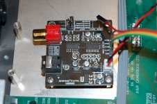
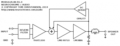
Modulus-86 is my latest amplifier design. It is a composite amplifier using an LME49710 precision opamp to control an LM3886 power amp. The performance of the resulting composite amp, both in terms of measured performance and in terms of sound quality, is dominated by the performance of the LME49710. Hence, the performance of the Modulus-86 is absolutely stellar. One of the many benefits of the composite topology is that the power supply rejection is very high. This means the Modulus-86 performs as well on a real power supply (I tested with a toroidal transformer, rectifier, and 2x22000 uF) as it does on a regulated, $1200, lab supply (I used an Agilent E3632A). The excellent supply rejection is also one of the main contributors to the stellar sound quality of this amp.
In addition to the LME49710, an OPA2277 precision opamp is used for the DC servo. The use of a DC servo avoids the use of large capacitors in the main signal path.
The input to the amplifier is provided by a THAT1200 differential receiver. This makes it possible to use the XLR connections commonly found in pro audio. The THAT1200 provides performance rivaling that of an input transformer. When using differential connections, this minimizes the induction of hum and EMI, resulting in dead quiet during quiet passages in the music. The differential input can also be configured for use with the single-ended RCA connectors commonly used on prosumer audio gear.
The key features of the
Modulus-86 are:
- 65 W (4 Ω) and 40 W output power (8 Ω) using a Power-86 with the recommended power transformer.
- Ideally suited for multi-channel amplification.
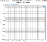
- Ultra-low 0.000061 % THD (1 W, 8 Ω, 1 kHz).
- Ultra-low 0.000067 % THD (40 W, 8 Ω, 1 kHz).
- Ultra-low 0.00038 % THD+N (40 W, 8 Ω, 1 kHz).
- Ultra-low 0.000067 % THD (65 W, 4 Ω, 1 kHz).
- Ultra-low 0.00041 % THD+N (65 W, 4 Ω, 1 kHz).
- Ultra-low 0.00069 % IMD (40 W, 8 Ω, SMPTE 60 Hz + 7 kHz @ 4:1).
- 0.065 Hz ~ 85 kHz bandwidth.
- 14 V/µs slew rate (fully symmetric).
- 84 kHz full-power bandwidth.
- 33 µV RMS output noise (20 Hz - 20 kHz, A-weighted).
- 42 µV RMS output noise (20 Hz - 20 kHz, unweighted).
- Differential input with 90 dB CMRR eliminating ground loops in the signal path.
- Phenomenal power supply rejection ensuring consistent, high performance even using unregulated power supplies.
- Elaborate use of planes and copper pours to maximize circuit performance by minimizing supply and ground impedances.
- Low-inductance signal ground connects to power ground at one point only for maximum performance.
- On-board Zobel and Thiele networks for maximum stability even with capacitive loads.
- On-board EMI/RFI input filter and ESD protection.
- On-board low noise voltage regulators for the driver op-amp and DC servo.
- Power and output terminal blocks accept wire sizes up to AWG 10 (5.2 mm2).
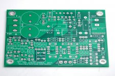
- All leaded. Easy to solder. 90 × 70 mm board footprint.
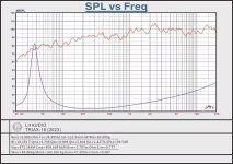
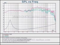
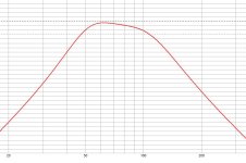
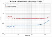
The THD+N is constant versus frequency throughout the majority of the audio range. The THD+N does rise slightly towards the high end as the loop gain of the amplifier rolls off. At normal listening levels (<1 W), the THD+N is perfectly flat versus frequency, resulting in incredible sound quality.
The differential input makes it super easy to use multiple boards in a bridge, parallel, or bridge/parallel configuration. All that is required to turn a stereo amp into a mono, bridged amp is that two wires are swapped. No component substitutions necessary.
The Modulus-86 has a gain of +20 dB (10x) for better gain structure in the end system. Should a higher gain be desired, the amp can be configured for +26 dB (20x) by changing a resistor. The circuit support the use of the THAT1203 and THAT1206 for gains of +17 dB (7x) and +14 dB (5x), respectively, should lower gains be desired for further optimization of the gain structure.
"But, but ... how does it sound?", I hear you ask. It sounds fantastic! The first time I turned on the Modulus-86 and started the music, I went “WOW!” before even making it to my listening chair. It was immediately obvious that this amp was something special. What struck me was the level of clarity of the reproduction and the deep quiet during quiet passages in the music. Talk about a huge dynamic range! I have played a few instruments in my life – including the trumpet and a brief stint with a drum set. It is especially important to me that metallic instruments (brass wind and cymbal for example) sound metallic and natural. This is an area that challenges many amplifiers and where the Modulus-86 really shines. The midrange is open and natural. The bass is precise and tight. What can I say? I really like it… The detail reproduced from Dire Straits, “Brothers in Arms” and “On Every Street”, for example, is out of this world. I am certain the incredible sonic performance is due to the stellar supply rejection and flat THD+N vs. frequency of the Modulus-86.
For those interested in more background information on composite amplifiers, I suggest reading the article,
"Composite Audio Power Amplifiers" in Electronics Now, Nov. 1992 (pp. 38-44). This DIY Audio thread contains a few pictures from the article:
composite amplifiers
For the impact of layout on the performance of an LM3886, I suggest looking at this DIY Audio Thread:
http://www.diyaudio.com/forums/chip-amps/252436-lm3886-pcb-vs-point-point-data.html
Finally, for a more complete picture, I'll direct you to my Taming the LM3886 page:
Neurochrome.com : : Audio : Taming the LM3886 Chip Amplifier
Thanks,
~Tom


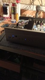


![20250311_211937[1].jpg](/community/data/attachments/1342/1342039-265af909e0304a0231650735f5d44c06.jpg?hash=QbXCkF9mEW)