LTspice XVII strange problem - Can't find definition of 2N3019 -- Help?

After years of running LTspice IV, I've recently switched to LTspice XVII. However, I've run into the craziest problem.
I've attached a .asc I'm working on. In it there are two NPN BJTs, a 2N3019 and a 2N2219A.
Both of those devices have models in the standard.bjt file in the \lib\cmp folder.
I put the two NPN transistors into the schematic in the normal way:
  • Click the Device icon in the toolbar
  • Choose the npn option
  • place that in the schematic
  • right-click on the NPN transistor symbol in the schematic and choose the model from the list; 2N3019 for the top one, 2N2219A for the bottom one.

Now when I run the simulation, I see the error "Can't find definition of model "2N3019' - Select OK to continue the simulation with the default model or Cancel to quit now".

1652752086654.png


What's crazy is if I replace them with PMOS MOSFETs, the simulation runs without complaint.

I'll attach my standard.bjt file so you can look and tell me if anything is weird in it.

I'll also attach the .asc file that's making this error.

Here's the schematic:

1652752387791.png


This is so strange. The MOSFET symbol works fine; that loads models from standard.mos with no issue.
But the NPN symbol simply will not load without that error.

This is the .asy file for the NPN BJT:

Code:
Version 4
SymbolType CELL
LINE Normal 44 76 36 84
LINE Normal 64 96 44 76
LINE Normal 64 96 36 84
LINE Normal 40 80 16 64
LINE Normal 16 80 16 16
LINE Normal 16 32 64 0
LINE Normal 16 48 0 48
WINDOW 0 56 32 Left 2
WINDOW 3 56 68 Left 2
SYMATTR Value NPN
SYMATTR Prefix QN
SYMATTR Description Bipolar NPN transistor
PIN 64 0 NONE 0
PINATTR PinName C
PINATTR SpiceOrder 1
PIN 0 48 NONE 0
PINATTR PinName B
PINATTR SpiceOrder 2
PIN 64 96 NONE 0
PINATTR PinName E
PINATTR SpiceOrder 3

And this is the line in standard.bjt that it should be calling:

Code:
.model 2N3019 NPN(Is=14f Vaf=100 Bf=200 Ikf=.75 Xtb=1.5 Br=5 Rc=.7 Cjc=16p Mjc=.36 Cje=55p Mje=.1553 Tr=800p Tf=800p Itf=1.2 Vtf=5 Xtf=55 Rb=10 Vceo=80 Icrating=1 mfg=Semicoa)

Can anyone see what I'm doing wrong?

Thanks.
Attachments

Hybrid RIAA/Line Amp

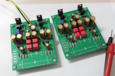
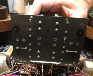
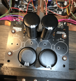
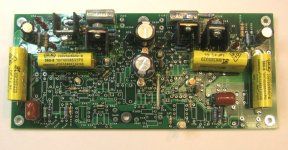
Attached is a view of a partially stuffed board that incorporates a hybrid RIAA preamp using a pair of submini Russian dual triodes with sand helpers, and a unique line stage utiizing a solid state triode emulator that acts like a gain-of-6 triode with 75 ohm output impedance. The fake triode is loaded with a cascoded current source to minimize stray capacitance and reduce distortion. The fake triode circuit shows impressively low distortion in simulation.

The top of the board contains the fully stuffed line amp. I'll be running some gain-phase plots on it tomorrow, along with time domain response. When I'm satisfied with the line stage performance, I'll finish stuffing the RIAA section and characterize that. This is one project that will likely make its way to this year's Burning Amp.
BTW, the board will be run from a switching adapter via a DC-DC converter of my own design.

Attachments

  • Img_2238.jpg
    Img_2238.jpg
    191.3 KB · Views: 1,440

Balance and Fader Controls for Pre Amp Line Level

Hi all

Firstly I am a complete newbie to all of this audio/elect. engineering. So apologies in advance if I seem confused, and thank you for any input or responses! Its my first foray into DIYAUDIO but I have learned a lot already. As I spend time on a classic car board being helped and helping others, I know how much value your help offers. I also ask you to be simple in your answers. I don't know the jargon beyond the very basics.

I am asking about Balance and Fade potentiometer controls for a very specific use case as a controller for stereo line level output from a BT receiving, splitting it to 4 channel, LF, RF, LR, RR in order to send it to a 4 channel simple 50W RMS amp. Before even diving into the idea of designing and building something, I would like to better understand some of the varying positions I have read about in my research of this subject.

Why? I want to be able to change the sound stage in my car while driving rather than via DSP presets on an expensive and big overly powerful amp. I am adding modern audio to a classic car (keeping a 'vintage' Blaupunkt head unit with cassette player. I am not looking to build a crazy system, just a 4 channel amp, better speakers and a BT ATX HD receiver. The BT receiver has no controller for the volume, it outputs stereo, not 4 channel, and has no balance and fader control.

Call me old fashioned but it’s nice to be able to make adjustments to fade/balance based on who is in the car and what music is playing. Since I can’t seem to find a line level fader/balance controller to buy, I figure why not try to build it.

In my research to date, I understand there are linear and taper pots, 10K and 100K recommendations for resistance, using non-Pot resistors methods, etc. All of which makes sense sort of, but I am left with some very basic questions…

  • Is there an actual balance pot, one designed specifically for balance or fade or both combined? Not just a regular liner or taper POT? I have not yet found one online
  • I understand the difference between linear and taper pots, is it correct that linear would be preferred or required for balance/fade functions?
  • Is there a significant loss of signal quality if one uses a regular linear pot with say the left channel of a stereo signal into the wiper and the resistor track lugs as output for left front and left back channels? If so, why? This goes to my question of using a standard pot for balance. Is a taper pot more appropriate
  • Can I simply arrange pots in a circuit such that volume, balance and fade are strung together to make the 4 outputs I need?

For Example:

Stereo volume:
2 gang taper pot with inputs on left resistor track lugs and output on wipers for left and right volume.

Balance: dual gang linear pot gang linear pot with inputs on wiper lugs and output on both resistor track lugs. 4 signals out.

Fader: 4 gang linear pot (one per channel) with LF and RF inputs on left resistor track lugs and the LR and RR inputs on right resistor track lugs, outputs on wipers.


If this all makes sense and if would work, then here are my follow up questions…
  • Would this sound like crap?
  • What would the input levels need to be for the output to be usable?
  • What total resistance pots would be best, 10k, 100k, other?
If other circuitry would be helpful, can you specify what components and what each does for the benefit of the signal? Remember I really know very little except the basics. Resistors resist, diode limit direction, capacitors store potential etc.

I can solder wires and things together, get them mechanically mounted and working, but designing much more than the above is way above my pay grade!

Thanks for any input.

where to find generic Polyurea coating?

Im getting ready to finish some tham15's and wondering if anyone knows where to get polyurea coating?

-Hoping for a non-proprietary, generic brand.
-Does home depot have such a thing under some other name?
-Kelly Moore?
-Might go with custom grey color if available.

Any tips for using this stuff? I was planning on taking it to my painter to spray but wondering if there is a special spray gun needed?

Sirius Pro

Hi guys,

I have a Sirius Pro MXA 6000 DJ mixer in for repair. It's a very complex unit and has a nasty fault on it (routing is all over the place) so without any schematics I'm dead in the water with it.

Would anyone here have a service manual or a schematic for this model?

I've asked Thomann who are the importers now and have been met with the usual line... "we don't give out schematics".

What the hell is wrong with companies these days? Do they really think that they will ever get repeat sales with this sort of attitude? I even called Braun, the previous distributor only to be told to contact Thomann.

I used to think that Thomann were a very switched on, helpful company. It seems not - they are just like the rest of the big companies that don't give a damn about their customers.

Can any one point me in the right direction with this?

Many thanks!

Project boxes - what are your faves?

I've been tweaking on several designs/topologies of headphone amps over the last year or so, and now it's time to put the four winners into enclosures. I have something appropriate on hand for one of them, looks like I'll have to buy the others.

With the Covid shutdown, I figgered it's not a good time to order direct from China. I found these on Amazon, not crazy about the color, and I'd prefer the long dimension to be the depth, but one of them is good size-wise.
https://www.amazon.com/gp/product/B08BS39P69/ref=ppx_yo_dt_b_asin_title_o00_s00?ie=UTF8&psc=1

What project boxes have you found that you like?

SD 12000.1 dc offset

Hey,

Im working on a blown sd 12k. One channel was shorted, other looks fine. I fitted new driver irs20957, 2x zxgd3005 and new zeners. I still have yellow led lit. When im feeding amp with just 12v with no remote i have 12v on high side gate/drain and 8v on source. Low side has 8v on drain and 0v on gate/source. But on the blown channel i have 12v on high side drain and only 1.6v on gate/source. Thus im only getting 1.6v on low side drain and 0v gate/source. I cant for the life on me figure out what im missing. And obviously i have 8v on one output terminal and 1.6v on blown channel terminal.
When measuring i have drivers etc removed from the board.

Attachments

  • IMG_20220508_112947__01__01__01.jpg
    IMG_20220508_112947__01__01__01.jpg
    398.3 KB · Views: 211

Counterpoint SA-220 problem...

My brother's SA-220 started smoking the other day and one channel quit working. I am taking a look at it for him, but don't have schematics for this.

U3 (AD42020-1) and U4 (AD736JN) both split in half. The portion of the board above these has smoke damage from this. VR1 and VR2 trimpots are both charred and the board below them is also damaged, though I haven't taken it apart to inspect how much damage there is.

I figured before I did much on this, that I would try to determine whether the output FETs are still good or not. I don't measure any shorts, but they also do not ohm out the same as the good channel.

Any suggestions? My brother would like this fixed if possible, but not looking real good right now.

If anyone has schematics, I would appreciate a copy also. I do have the SA100 schematic that was floating around, but this problem at least so far seems to have started in the thermal tracking portion of the board which isn't on there. Thanks for any help, and I can post pics if they would help.

VOX AC30 CC2

Hi

Someone send me this amp and told me that the rectifier tube has blown and the amp has been modified using solid state rectifiers (Diodes). Since then it has been running very hot. He wanted the diodes removed and put back the GZ34 rectifier as before. I have replaced the diodes with the GZ34 and the amp is working fine. The problem I noticed is that, whenever I switch ON the standy switch, there is a bright arc inside this rectifier tube. I guess that this arcing will eventually blow the tube as before. Can the standyby switch be removed or is there any other way about it. I cannot post the schematic as it is 1.95 MB bytes

Please advice.

Thanks

FS: JFET MC photo stage RJM audio CrystalFET 1.2a

MC passive phono stage built around J113 gain/buffer stages. This is version 1.2a of the circuit (built 2016), the gain is fixed to 56 dB (about) and the input load is 100 ohms. It is wired for Canadian 120 VAC line. The internal photo was taken in 2016, the external photos are recent. The difference is the older photo shows RCA connectors that were afterwards upgraded to Furutech.

Some build notes can be found here
more info here and here

Asking $200 US, shipped. Located in St. John's, Newfoundland, Canada.

Attachments

  • image003.jpg
    image003.jpg
    139.1 KB · Views: 173
  • image005.jpg
    image005.jpg
    160.9 KB · Views: 208
  • DSC_0987.jpg
    DSC_0987.jpg
    419.2 KB · Views: 192
  • DSC_1739sm.jpg
    DSC_1739sm.jpg
    387.6 KB · Views: 194
  • IMGP6826.jpg
    IMGP6826.jpg
    298.9 KB · Views: 175

Can we get a new section for all in ones?

I'd like to post my boombox project, but there doesn't seem to be a section for that. There's a loudspeaker section and an amp section, but nothing specifically for all in one units like boom boxes, etc. Could we perhaps get a new section for that, or where should I post it? I searched and found them all over the place from the subwoofer section to the full range section. 🤷‍♂️

Goodmans Dimension 8 Speakers.

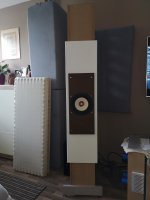
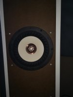
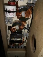
I have to admit i saw these and had to have them. I never seen anything like it before, these things were built in 1971 by goodmans. 4 Bass drivers with a passive 12inch bass assist, 2 mids and 2 tweeters.

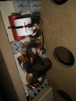
So my aim is to give them some TLC, usual things like check the drivers, the crossovers could probably do with new parts etc.

Hoping someone out there has experience or knowledge to assist me! But i am really intrigued by these and want to have them running as Goodmans intended!


XlFztwF.jpg


Uh81X0q.jpg


oL3wKox.jpg


5nbWjjV.jpg

Problem with cone excursion in winISD

Hello! I'm attemtping to design some enclosures for a modest pair of bookshelf speakers.

I've been looking at using the Dayton Audio DC130B-8 5-1/4" Woofer.
I'm hoping for my enclosure to be roughly 9L in volume, with a 6cm diameter, 30cm long vent, tuned to 52hz.

I thought I was on the right track in terms of picking a suitable driver for the volume and accounted for potential chuffing with the vent size+length, however I've run into a major roadblock relating to cone excursion. No matter what I can't seem to get the cone excursion below the x-max limit of 2.5mm which I'm told will distort and potentially damage the driver. I'm testing it at 40 watts which is the RMS given in the spec sheet.
I've even tested a few kits with premade drivers to see if I was entering the driver data wrong and I'm seeing similar issues with the x-max. Am I doing something wrong or is winISD just cooking it a bit? I've gone back and double checked all my driver parameters and tested on a different computer but no dice.
The only solution i've found is to add a high-pass filter at 120hz which will remove the bass entirely and I really don't want to do that.

Is this just an indication that the driver is no good? It makes no sense to me as I can't find any enclosure size that would work for this driver.

Any help would be greatly appreciated.

Attachments

  • ConeExcursionProblem.png
    ConeExcursionProblem.png
    21.5 KB · Views: 129

de-spidering a cheap driver?

What do you think would happen if you removed the spider from a small 2-3" full range driver?

Would the voice coil just stray off center and ruin it?
These kind of small and shallows FRs are sort of close structurally to being cone tweeters already so I think there is some chance it could work.
Whether it would work well and actually benefit something is another question.

I was thinking about this into a relation to using a cheap small FR (CHN40, P830985, Faital 3fe25) as mid tweeter in 2 way, and making into poor mans Alpair 5.3.

Acoustic Signature Wow Power Supply

Hi guys! Can you recommend where I can find a diy solution or a 3rd party product to replace the AC-1 Linear power supply of an Acoustic Signature WOW (Non XL) turntable from 2014?

Acoustic Signature hasn’t been responding to my emails and local distributor wants me to buy the AC10 charger (for the xl and xxl tables) for 700euros which is 3/4 of the cost of the turntable.

Found a 3rd party supplier on the web but he is out of stock and charges steep 419Euros

Sbooster | 24V upgrade PSU for your Acoustic Signature WOW XL

The AC1 ends into an RJ45?? cable hence my difficulty in finding a replacement.

Thanks in advance!

10" + CD/Horn 2-Way

Hi All,

Hope you're all keeping well!? It feels like an eternity since I made some speakers (a year, in fact) so it's time to upgrade my system.

I'd like to try a 10" mid-bass and CD/horn as a step up from my current 8" mid-bass and CD/horn. I could potentially go to a 12" but I would have to be careful with WAF.

Crossover frequency should be around 1000hz-1300hz

So far my plan is a little rough but I have been looking at the following drivers:

Mid-bass:
Faital Pro 10PR320
B&C 10HPL64
B&C 10NDL64
18Sound 10W500
Precision Devices PD.123C001


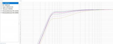
Rough sims attached. All tuned to around 55hz with 23-30L vented cabinets.

Compression drivers:
Faital Pro HF108 (super flat response and low xover)
Faital Pro HF108R (ihigher FS than the above that means I won't be able to crossover as low?)
Faital Pro HF10AK (reports suggest this doesn't cross as low and impedance graph doesn't look as good)
RCF ND350

Horns
- RCF H100 (constant directivity and loading to 800hz)

Caveats And justifications:

- Budget is around £100-£200 per mid bass driver and up to £150 per compression driver.

- I would like to try a constant directivity horn and I would like to keep it a 2-way

- This will be a bi-amped DSP system

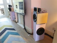
- The tuning of the mid-bass doesn't seem very low but my current cabinets are tuned to 75hz and because I am against a wall and so speakers are against the opposite wall I get good low frequency boundary reinforcement and the system -3db is around 40hz. With a lower tuning I expect to room to give me more low end extension (I have simmed in REW)

- I would like to use the EBS alignment as the aforementioned boundary reinforcement means I can adjust the bass-to-mid balance as the room dictates

- If I can support UK driver manufacturers then great, I'd rather not import drivers unless from a domestic supplier because of import taxes

Questions:

- Drivers. What would you suggest? Totally open to suggestions.

- With the EBS aliignment one obviously loses sensitivity (which isn't an issue) but does attentuating the upper response to match the lower have any detrimental conqsequences? IMD?

- Why do people investigate making 10" 2-ways and seemingly never build them? Is there an inherent flaw?


Attached is mid bass sims and a pic of my current setup where the subs have been switched off for the last 9 months.

Any suggestions welcome 🙂

Attachments

  • 10 Inch Mid Basses.JPG
    10 Inch Mid Basses.JPG
    178.9 KB · Views: 1,649
  • 20201201_092027.jpg
    20201201_092027.jpg
    771.5 KB · Views: 1,643

Rogers Developments UK HG88 Mk1

Hi - about Rogers Developments UK HG88 Mk1
I'm wondering if you or anybody can help w/ the above. I've been working on this amp, where 1 channel was dead.
BTW, before the 2 ECL82's there's an ECC83, which has a mistake on the diagram:
Both sides have 1, 2, 3 for both Triode sections. A 2nd section must be numbered 6, 7, 8.
.Finally, I figured out that the #1 contact in this socket hasn't made contact w/ the tube's foot. I took out a contact from another 12 contacts tube socket, filed the sides & thickness - then inserted in the ECC83 socket. Re-soldered the 100K & coupling cap = problem solved.
While snooping around, I also found 2 leaking coupling caps in the said ECC83 & bchanged the Cathode 1K resistor(out of specs).
I think that the problem w/ the socket was caused by my taking in/out the ECC83 for testing on my "bible" AVO VCM3 tester(calibrated twice by me & 2nd time installed a re-manufactured 33uA Taut Band mtr from jacmusic in Germany. Of course I matched all the tubes via the AVO.
But, here's my real problem: this amp has rectifiers for the hi voltage - the originals have been paralleled by Silicons. From there - there're 2 power resistors(w/ the usual lytics(I paralleled w/ new due to hum) in a Pi network.
Unfortunately, I only have the CCT - but not the resistors values. Of course, I can read all the resistor values from their color coded bands.
BUT, the 2 filter power resistors(1 for each channel within the usual 2 lytics) - 1 was dead & the other has faded value on it. I measure 480 ohms, but that's an unusual value - perhaps 500?
Does anyone have a chart w/ the components values he can attach to his answer?
Thank you in advance, Dany, Toronto, Canada

Understanding weird performance of AST25120

Hello,

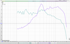
I purchased a pair of AST25120 tweeters and they don't conform to their specification at all. They don't have a flat response at all and can't produce any high. I don't think they are broken as their distortion number as low as my noise floor and DC resistance is 8Ohm. Also both brand new drivers measure exactly the same. I started questioning my equipment and measured a Dayton audio AMT mini 8 and I get a response curve very similar to their specification. Any idea what could be wrong there ? (I tried two different amplifier too).

PS I attach the measurements,

Thanks!

Attachments

  • Screenshot from 2022-05-21 20-54-08.png
    Screenshot from 2022-05-21 20-54-08.png
    30.9 KB · Views: 198

Troels Gravesen THE LOUDSPEAKER 2 Build... or something very close to

Well, after 10 different DIY builds (Troels Gravesen, Zaphaudio, Paul Carmody, Jeff Bagby and my own designs) I have decided to “retire”, what means build the “definitive” speaker. I have moved and now I do have some dedicated space for …. The Loudspeaker 2 from Troels Gravesen… or something similar.

First of all, THIS IS NOT THE EXACT DESIGN FROM TROELS: I have changed the insane expensive BMS 18” for the much cheaper and very good performer Faital Pro 18FH510 because I was going to drive it in active mode anyway and I was confident I could make a good active crossover to mix to the upper section.
I’d like to share this build to help others to decide if build it or not and to avoid lots of mistakes and problems that this build can bring.
The system has been driven from an active crossover based in Troels cross points (200Hz, 1300Hz and 10kHz) but as my 18” has more sensitivity than the Troels one, I want to build a passive crossover to use this beast with tubes.
I have tested some passive crossovers but I’m not comfortable with the results. i’m taking new measurements and modeling a new crossover and let’s see what I can get. Please, do not ask for crossover values because there is some kind of everything here: lots of tricks and info gotten from here and there. Nothing 100% reliable, but I will post my frd and zma files to see if, with your help, we can approach a good crossover.

Lets go back to the build:
I have sourced all the drivers at the best price I could at Audio Video Parts
Carlo is a very serious person and you can trust them.
Second thing: Please, if you want to build this speaker, GO FOR CNC. And put this sentence in your mind: GO FOR CNC… and you will build this speaker in 30 hours maximum with no failures or problems.
It looks to be an easy build because there are no flanges or shapes, all is squared… but BEWARE WITH THE DOG. This is a very HUGE speaker and its very difficult to build some parts without good help, and moving it is almost impossible.
I have build these beasts in just 5 weeks with no help. Only my own due to COVID-19 lockdown. It’s not an easy job and it took me like 200 hours, but the final result worth the pity and the money. The sound is really incredible.
I could source all the wood, screws, glue and everything before the lockdown, but any mistake or any change I had to solve by my own. There was no chance to find any more parts outside.
I have used birch wood for all the speaker unless the front baffle, built in bamboo. Inner braces were built in pinewood.
Here you have some pictures from the scratch.

Wood cuts:


Subwoofer power amp setup?

Hello all, hope your all having a great day.
I work for a non profit for children.
I was donated two marantz sr6011 avrs and 6 sound town nx 4 channel amps 750 watts per channel. Last but least about 30 speakers. It's to setup a audio system for movies and plays.
I got most of it wired but having a problem with the subwoofers. I am using 1 of the amps for two subs bridged. Sub one to channel 1 and 2. Sub 2 to 3 and 4. How to I hook up that amp to the avr? I tried to the subwoofer out and it's very low. I also tried in the preouts and get nothing. The subwoofers are 800 watt 12" passive. Also is any settings in the avr would be a big help to make it sound better.


Marantz sr6011 x2
Sound Town 4-channel NIX-6000X4 x6

Isophon P25A pair. Great condition.

In great working condition. Seem to have been well cared for before I got them some months ago. Hooked up this morning to make sure they worked well and they do. Sound clean and clear.
Troels has a project with them. There's a couple others out there, but I no longer have my notes for them. High Q could be good for ob. Might work well in waw.

Asking $120 plus shipping to usa lower 48.

Thanks, Don


20191002_122417.jpg

Attachments

  • 20191002_122635.jpg
    20191002_122635.jpg
    588.4 KB · Views: 1,089

ESLs have bad decay plots

Hello all,

During time I've collected all kind of information about esls.
What strikes me is that all cumulative spectrum decay plots (CSD) from ESLs I've seen sofar, all show resonances at mid and high frequencies. Not very bad, but very good (dynamic) tweeters are able to exceed the ESL on this excercise and show CSD plots with a more rapid decay.
This is somewhat against the popular belief that the ultralight esl-film is effectively damped by the surrounding air and immediately stops with no ringing.
In a dutch book (Fikier) it is stated that the delays shown on a CSD plot can not be heard as they are 'masked' in case of an ESL. But I couldn't find any theory supporting or explainig this. The only thing I can think of is that the several resonances will cancel at a longer distance as they travel across the film while the CSD plot is closed miked and shows a small area only.
Does anyone have some opinions about this masking effect?
( it may help to explain the subjectively experience of micro-resolution in ESLs)

Martin-Jan

Source impedance of a bifilar transducer

Ok. I've been working the following scenario over and over in my head and I need to be sure I have it figured right:

Let's suppose we use a magnetic pick-up (a rod magnet wound with N number of overlapping turns of magnet wire) near an oscillating metallic object to generate an AC voltage. When we measure the source impedance, we measure the DC resistance of the of the magnet wire, correct? For the sake of practicality, let's suppose the DC resistance of N number of turns is 1Kohms.

This can be modeled (within reason) as a voltage source in series with a 1Kohm resistor with a capacitor in parallel (capacitance of magnet wire winding). Simple enough.

Now let's suppose we require as high a signal-to-noise ratio (SNR) from the source as we can get. For this purpose, we desire our AC signal to operate as a balanced source which is then run into a Balanced-to-unbalanced converter of some sort (either passive UnBal transformer or active opamp). Still with me?

Here's where things get tricky:

So the magnetic pick-up is wound in a bifilar fashion: we take two parallel lengths of magnet wire (wires "A" and "B"), each length (naturally) having two ends, or "taps"; an inside winding tap and an outside winding tap.

Because two wires have twice the volume of one, we wind wires A & B in parallel N/2 number of times around the rod magnet. We then connect the inside tap of wire A to the outside tap of wire B (or vice versa).

At this point, here are the facts as I understand them:

1) We are now left with two taps: an inside tap and an outside tap, the instantaneous induced voltage at each tap is 180 degrees out of phase respective to the other. Therefor, these voltages can be said to constitute a (floating) balanced AC signal.

2) Because we used two lengths of wire, each half the length of the example used up top, the DC resistance of each wire is 500 ohms (1/2 of 1Kohm).

Here are my questions:

1a) In my mind, I see two 500 ohm lengths of wire in series. Measured tap-to-tap, the source impedance is still 1Kohm. However, since the winding "switches direction" where wire A is joined to wire B, I imagine a "floating" node forced to reference when the output taps of the pickup are connected to the input of the BalUn stage. Or is the DC resistance of the windings just the real (non-reactive) component of the impedance?

1b) Would grounding the point where wires A & B meet cut the source impedance in half?

2) What happens to the self-capacitance of the windings that are out-of-phase? Is it electrically canceled out? Cut in half?

3) The SNR is increased by a factor of 2, correct?


I think that's about it. Thanks to anyone who can help me out here.

Expert advice wanted

Please find the schematic below. Can an electronic expert explain to me the exact function. Input is ~300VDC at R7. The unit works as expected and smoothly ramps up to 280VDC in about 5-6s, nice. The R7/C7 (R10/C8) function I do understand, it’s time delayed charge of the capacitors which slowly starts the conduction of the regulator mosfets. What is the function of D4/D5 and R9?
Q2: I setup a simulation on LTSpice which stops with a Too Small Time Step, blah, blah, blah after 5.8s. Any advice about the correct LTSpice settings. I suspect this behavior has something to do with the zeners…
Simulation file attached.
612853CF-2E9A-4553-AEC8-C705B41AE05B.jpeg

Attachments

Help in understanding PS Filtering

Hi,

I have a HT supply to a pair (one in each channel) of 6c45 valves. I took some photos of the circuit that filters the B+ as I think the hum could be quieter, however I did not take any measurements as I thought I would be able to just work it out......but sadly my brain is not large enough to achieve this :-(

What I am very confused with is the large value of the resistors that seem to be used as part of the RC smoothing filter that I assumed was the configuration. The caps are 220uF and the resistors look like 470K?!?

I clearly need to go back and measure things, but alas the amplifier in question is absurdly heavy and on a re-enforced shelf that to take down safely requires 2 people (one of which is not my wife) - so is by appointment rather than by choice.

Any ideas on what is going on with the circuit - I thought it would be simple to see.

Attachments

  • Screenshot 2022-05-12 at 14.32.00.png
    Screenshot 2022-05-12 at 14.32.00.png
    1.4 MB · Views: 115
  • Screenshot 2022-05-12 at 14.38.34.png
    Screenshot 2022-05-12 at 14.38.34.png
    1,012.4 KB · Views: 124
  • Screenshot 2022-05-12 at 14.39.16.png
    Screenshot 2022-05-12 at 14.39.16.png
    1.2 MB · Views: 145

Does anyone have experience with 12AH7?

Just wondering if anyone has used this type and what their experience was with it.
It looks like a 6SN7 type of octal twin-triode but with a 12.6V 150mA heater.
Maybe that makes it more like a 12AU7 in an octal bottle. ??
However, the Cag is high, like 3pF, as compared to 12AU7 Cag of only 1.5pF, and 6SN7 Cag of 4pF.

12AH7 datasheet: http://www.nj7p.org/Tubes/PDFs/Frank/hb3/12AH7GT.PDF

Thanks.

For Sale IanCanada IsolatorPi II galvanic I2S isolator

IanCanada IsolatorPi II galvanic I2S isolator for a Raspberry Pi or ODROID. New €80, bought from Audiophonics on January 11, 2021. Asking price €59 50 excluding shipping from The Netherlands.

As good as new, where I have soldered power wires directly to the board. The GPIO header does not pass 5V to the HAT above. For that, you can use the Molex terminal. Myself, I attached the power wires to my Allo Kali reclocker (see my other listing) above to this terminal.

Manual: https://github.com/iancanada/Docume.../IsolatorPi/IsolatorPiIIUsersManualRev2.0.pdf

tempImagec1n2fJ.gif


tempImageDD0mTr.gif

Cello Performance Supply II voltage

Hello, I recently acquired a Cello Performance supply II and amplifier. Unfortunately, the cello performance supply emits a constant static noise from the supply when turned on. It is currently wired for North America voltage. How can I check it's wired for 120V (as opposed to 110V). I read in another post that the maybe due to insufficient voltage. I have attached a picture of the supply in question.

Thank you

Friend with an old amp

How do I get into these things, must be I like punishment, brother in law told neighbor I like tubes, expert, since I built three amps.

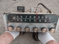
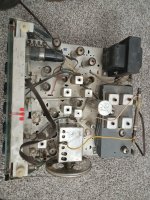
Anyway I need some help!

Here is the amp:

Symptoms bad hum. Suspect 60 hz hum, bad ps caps, cannot clearly read values. Not many caps total, probably redo them all. I haven't tested the tubes yet either.

Anyone recognize this critter?

Attachments

  • 20220520_112513.jpg
    20220520_112513.jpg
    387.8 KB · Views: 175
  • 20220520_112524.jpg
    20220520_112524.jpg
    543.8 KB · Views: 181
  • 20220520_112411.jpg
    20220520_112411.jpg
    692.9 KB · Views: 180

FS: Speaker Builder's Dream Part II Celestion Axi2050, GPA Altec 288, B&C DE550TN, Hypex NCore Kit, Topping E50 Dac

Selling the following:

Celestion Axi2050 2" Compression Driver Pair New:
https://www.ebay.com/itm/275314410523

Great Plains Audio Altec 288 1.4" Compression Driver Pair New:
https://www.ebay.com/itm/275314408562

B&C DE550TN Compression Driver Pair New:
https://www.ebay.com/itm/275314405100

Hypex NCore NC400 Complete Kit Pair New:
https://www.ebay.com/itm/275314420913

Topping E50 Dac Silver New:
https://www.ebay.com/itm/275314427894

Volume control for TPA3251 based amp.

Hey guys,
I've decided to build my first amp based on this guide.Full Page Reload
The amp board the author selected is not available, so I went with the EAUMT-0140-2-A, which is TPA3251 based.
I realized that this setup does not contain a volume control of any type, and assumes that I own a pre-amp.
I plan on feeding this with input from my computer soundcard and phone. I'll be using a 3.5mm jack instead of the XLR jack, as I don't own any devices that use XLR. Can I just use an audio tapered pot to control the volume? Should it go on the input or output side? Do I need buffer capacitors? What rating?
Will these inputs supply sufficiently strong signal or will I need a preamp to boost them?
If I need a pre-amp, I'd like to integrate it in the housing, I have plenty of room. I looked at a number of pre-amp boards, but there are many available and I have no idea which are good and which are garbage. Any advice would be helpful.
I've been searching for answers to these questions here and elsewhere, but I don't know the keywords to find what I need.

Can a 5751 be used in place of the 12AX7 in TU-8600S?

I'm using my TU-8600S with a preamp, which allows me to connect to multiple sources and produces a more dynamic bass. The gain is now too high. I have to turn the volume knob on the TU-8600S to 2-3 o'clock position to make the noise from my preamp inaudible.

I'm wondering if we can replace the 12AX7 with a lower gain variant such as the 5751 so that we can turn the TU-8600S volume pot to maximum position, effectively taking it out of the circuit. The volume will be controlled only by the preamp.

Any thoughts?

Reclaimed heatsink dissipation

I have salvaged a couple of skived heatsinks from old Carver 900 receivers. They used to hold 6 x TO-3P (2SA1264 & 2SC3181) and 2 x TO-126 (2SC1846) transistors.
If I wanted to estimate their R(theta), I was thinking to run a hefty transistor in a single-ended Class A operation, like a MoFo., and then measure the voltage & current across D-S (to get power), and the temperature at the gate pin.

Thoughts?

Kind regards,
Drew

Beginners OPA1656 oscillation

Hi,
I'm just starting out playing with circuits and I wanted to play with the OPA1656 and I took a circuit from the application notes found in the op amp datasheet. it has a Baxandall treble and bass controls with a little bit of gain and thought it would make a nice headphone amp that would run from two 9v batteries so I drew the circuit into a circuit SIM (Tina TI) and it appeared to me to work and I could see the top and bottom of the frequency range adjusting as I would expect with a fixed gain. I then copied it into KICAD and designed a small PCB and built it (see attached PNG) on power up I hear
OPA1656.png
d music and it sounded reasonable at first, I was flushed with success ! but there was a lot of hiss and when I adjusted the treble it got considerably worse yet the bass adjusted as I expected. I then looked at the output with a 33 ohm load on a scope and could see hundreds of mV of oscillations at around 1 MHz that went away if I had the treble full up (Fully Clockwise) but any adjustment made it spring into oscillation, I had an input signal of 1 KHz at around 1v RMS. I have sat and thought about it and can only think it is capacitive either to much or too little but no other thoughts really other than I have made a fundamental error and there is a lot missing, bypass caps could be closer to the chip but they are there and its batteries anyway. I am not sure if I'm in the right part of the forum but I'm hoping for some advice please.

Cheers
Andy

Passive radiator on rear of narrow speaker; baffle step considerations

Theory question here. A narrow speaker can suffer from lesser amplitude of low frequencies in part due to the loss of a beneficial baffle step. What happens when a passive radiator is introduced to such a narrow speaker, on the rear or the side; does this help overcome the baffle step losses? My understanding is that frequencies below the baffle step turn omnidirectional, whereas those above are radiated in a forward plane. But when a PR is added, surely this means all the lower frequencies it helps with are radiated omnidirectionally?

An example of such a narrow speaker would be the Swiss Boenicke W5, which uses a side PR.
And my theoretical question would concern employing a PR to the rear of a speaker like a Gallo Micro or similar.

Thanks in advance.

CDM-2 Servos - Static vs. Dynamic

I was playing around with a few of my CDM-2 based CD players the other day, swapping the mechanism out of a player I had junked (a CD650) into a CD150. The laser mech from the CD650 just would not track well; tracks one to five were fine, track six was getting marginal, and beyond that it would not track at all. I checked the normal things (friction in the bearings etc.).

It was then that I did some reading, and came across an issue I had never considered before: Static vs Dynamic CDM-2s. It seems that the CDM-2 had two types of radial drive, static and dynamic, and there are different servos for each. This results in four different servo panels:

- No.5725 (static radial drive, on board microcontroller)
- No.5768 (static radial drive, off board microcontroller)
- No.5826 (dynamic radial drive, on board microcontroller)
- No.5827 (dynamic radial drive, off board microcontroller)

And within the model CDM-2/10 there are eight variants:
- Static models; 0000 (Hi-Fi), 0001 (Top Hi-Fi) and 0003 (Leuven)
- Dynamic models; 0008, 0300, 0301, 0303, 0307

Now at the moment I have three CDM-2 laser mechs (a 0000, a 0001 and a 0301) and four servo boards (three 5725s and a 5827). I'd like to run the 0301 laser mech in my Philips CD150, but I need a 5826 servo panel to do this. I've had a look at the schematics of both the 5725 and 5826 servos, and there isn't a whole lot of difference, about half a dozen passive components in the radial drive.

My big question is: Are there any other differences between a static and dynamic servo, especially with the microcontroller programming? Am I going to get a servo that works with dynamic CDM-2s in a CD150 by swapping out those half dozen passive components? I have shown a block diagram of the servo below, with the radial tracking and drive portions highlighted.

An externally hosted image should be here but it was not working when we last tested it.


And before this I thought a CDM-2/10 was just a CDM-2/10 :whazzat: . Anyone out the care to elaborate on the difference between the static and dynamic radial motors? And does anyone know if the other CDM-2 variants (the /29 etc) are static or dynamic? I would guess dynamic, but I'm not sure.

For Sale "WHAMMY" Pass DIY headphone amp pcb

Hi,

i have a "WHAMMY" Pass DIY headphone amp circuit board for sale.
Thread: https://www.diyaudio.com/community/threads/whammy-pass-diy-headphone-amp-guide.317803/#post-5317268

Cost: 20€
Shipping in a padded envelope without insurance or tracking:
  • D (without islands): 2,50€
  • World Wide (sorry .. no UK, to much paperwork for the customs): 4,50€

whammy_pcb.jpg

CDM 2/29 Problem – HELP!

A few days ago I was doing some work with my Grundig CD 9000. I found that the four-lead cord from the servo board is quite stiff and that it pulls or pushes the wobbly CDM, so I decided to change it with more soft one. I changed the solid wires with the litzy wires that I took from microphone cable. I got stuck with the little connectors for hours just to find that I have fitted two ends in wrong order. I had no more patience to disassemble all again so I cut the wires and soldered them together in proper order. I checked with DMM all fine.

I fired up the player and it started spinning the disc but doesn’t recognize it.:dead: The laser makes two tries upon startup, up and down, but no lock… Since than I have been searching and reading but found no solution that works for me… I have found service manuals only for similar players but there is no servo or CDM schematic… My player uses the same main board as Philips 640, 650, 660… but CDM 2/29.

I can provide photos of the board/player for someone that has the patience and goodwill to help!

Could it be that new no solid wire makes the problem?

Here is the photo of the servo board (without THE cable)

Attachments

  • servo-up.jpg
    servo-up.jpg
    66.1 KB · Views: 1,028

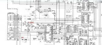
Denon DCD-1460 problem with KSS150/210 laser.

I have problem with Kss150-210 laser in Denon dcd1460. After inserting disk, lens go up an down, disk not rotate, just move a few degrees and no disc. I changed laser optic (removed safety blob) to another and problem is the same. Test run gives result Error 2 ...no FGS (focus gain signal) detected, Measuring current on driver transistor shows voltage drop of around 1,4v on 22r ,so around 65ma current sucks the laser. Voltage on Laserled suply jump to 2v after play. No eye pattern is vissible on test pins. I cleaned laser start position switch.
I am confused that new laser is damaged because it shows same symptoms. Any help where to continue'
Thank you.

Attachments

  • denon.jpg
    denon.jpg
    195.7 KB · Views: 240

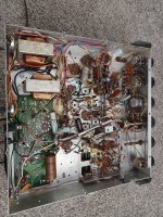
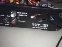
CORZUS MD3000 (FALL error )

Hello everyone ! I have this corzus md3000 amplifier that writes FALL on the display. I checked all the mosfets of both the pwm and the power amp and they are ok, the amplifier uses some irs2092 that I replaced and I also replaced some optocouplers! Do you have the schematic for this amp? I searched the internet but couldn't find anything! Thanks and good job

Attachments

  • 20220519_142745.jpg
    20220519_142745.jpg
    314.7 KB · Views: 268
  • 20220519_142740.jpg
    20220519_142740.jpg
    637.5 KB · Views: 295

Reduce Amplifier Gain - Existing Circuit

I have this Fisher amplifier I'm slowly getting in shape for actual use. It's one of those "console" amps that's a separate chassis, but when you remove the rest of it (tuner, preamp) the remaining circuitry within the amp chassis is all screwed up. One problem - after getting the voltages close to the schematic values - is the gain is way higher than I'd like.

Referring to the schematic, the 1st 12AX7 stage has a 470K plate resistor, the highest value I've ever seen (besides a 1M once). I'm thinking of reducing it, but, I'm also thinking doing that would change the feedback gain as well. Given the way that's all coupled to the phase splitter, I'm wary to touch it.

I could simply attenuate at the input by adding a level control - means drilling the as yet "unmollested" chassis for it. Or a resistor after the 47K from grid to ground. That would swamp whatever the 3pf cap does, perhaps changing whatever character the amp once had... Perhaps I shouldnt worry about it.

Any ideas? Thanks!

Fisher_Part.png

starting a new website

Hello to all,

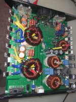
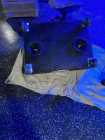
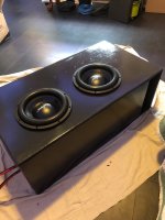
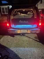
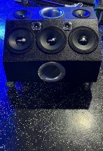
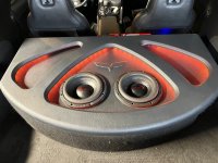
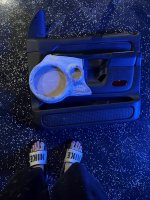
I have started a new website/business that is based on the focus of making things affordable for the common man. This is aimed at making boxes for way cheaper than normal, beauty plates, amp racks, custom fiber glass door panels etc. I also make aeroports for way cheaper than bigassports.com and are the same exact thing. My goal is to drop the price of what it cost to have a car show class stereo system. Check out enuffengineering.com at the moment i havent fully gotten everything up but we are a company based in Springfield, IL. Feel free to contact me with any questions or needs.

This is a no bs website with money back guarantee. if you are not happy send it back ill refund you with no problem.

some pics are not all the way finished projects, some are mobile sound, one is a center stage box i did for a club, others are car audio. pics are just meant to show examples not show fully finished projects.

Attachments

  • image6.jpeg
    image6.jpeg
    890.2 KB · Views: 108
  • image5.jpeg
    image5.jpeg
    375.2 KB · Views: 99
  • image4.jpeg
    image4.jpeg
    626.4 KB · Views: 93
  • image3.jpeg
    image3.jpeg
    682.3 KB · Views: 94
  • image2.jpeg
    image2.jpeg
    457.9 KB · Views: 91
  • image1.jpeg
    image1.jpeg
    1.1 MB · Views: 104
  • image0.jpeg
    image0.jpeg
    698.6 KB · Views: 99

Class D Vs Class I (Balanced Current Amplifier)

Was wondering if any electronics engineers could offer some technical opinions
on the subject.

Which topology is better, class-d, class-i or even class-h ?

From my limited experience in audio, I've learned that most arguments come
down to application, but since they're all a form of digital, perhaps there is
a "better" choice. When I say better, I'm thinking manufacturing costs,
reliability, sound quality and THD etc. Perhaps Class-I is just marketing hype?

I've been toying with the idea of contracting out some designs, hence the question. Application would be _big_ sound...pubs, clubs, events
and competition car audio. The dream is something along the lines of crown's
i-tech and JBL's 6KW beast http://www.caraudiomag.com/specialfeatures/0205cae_jbl_6000_watt_crown/photo_03.html ....probably not quite so big, but along competition lines.

6SQ7 - EL34 SE amp design

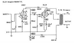
This is an SE amp I designed to use the very linear 6SQ7 high gain tube as a driver, built with some Edcor 15W 3.5k OT, to a UL tapped EL34. This amp sounds fantastic and is a simple/cheap design to build. It drives to full power without a pre-amp, which works great with my EAR 834 clone phono stage or straight from a CD deck.

I've tried a variety of 6CA7, KT77 etc. and settled on a pair of JJ EL34 tubes. I played around with various cathode bias schemes (I had no interest in a grid leak bias design I saw some circuits use with this tube), and the combo of a LED + resistor, and tying the diodes to the cathode, sounded the best. Like my other amps, it uses plate to plate Schade feedback and any UL tapped OT from 3.5K to 5K should work fine.

In the future I plan to do another video series on building this amp, but given I found very few designs online for the 6SQ7 tube used for hifi, I thought I'd go ahead and share this.

Attachments

  • 6SQ7-EL34-Single-Ended-Tube-Amp-Stephe-Final.png
    6SQ7-EL34-Single-Ended-Tube-Amp-Stephe-Final.png
    228.4 KB · Views: 3,162
  • 6SQ7-final.jpg
    6SQ7-final.jpg
    61.5 KB · Views: 2,620

Converting Pass Aleph preamp to unbalanced operation

I apologize upfront for what may be a dumb question.

I have a PCB for a Pass Aleph 1.7 preamp. It is balanced input to balanced output. I don't run balanced gear. I know I can use it as designed to accept single ended input and output single ended, but am wondering if I can convert it to just single ended operation.

Attached is the schematic. Would it be as simple as just populating the left side of the schematic and using "+IN" and Gnd for the input and "-Out" and Gnd as the output? I realize this would invert the signal.

Thanks for your thoughts.

Attachments

For Sale An Army of Iron...

I have an Army of Iron for sale: 4 counts of Hammond 193R chokes, 4 counts of Hammond 193U chokes, 4 Antek AS-2T230, 2 counts of Hammond 193A, 200H plate chokes, and 2 Silk grid chokes... all in the amp pictured, not to mention separate power supplies for each tube and the collection of poly chokes within. I am entertaining offers. Of course the entire amp is up for sale if you'd like. Come see me at Chums Corners just outside of Traverse City Michigan. I have several amps and much back stock that I must part with.

Attachments

  • tempImageYg5dL4.gif
    tempImageYg5dL4.gif
    1.6 MB · Views: 374

Gale Gold Monitors Mk1

New to this forum.....hi to you all.
Never really dabbled with hi-fi fault-finding/fixing, just wanted to get that out there 🙂
Recently collected a free set of Gale Gold monitor mk1 bookshelf speakers which came along with an amp I was after. Having read the reviews for these speakers the suggestion is that they are decent budget speakers, let down by wayward treble. Connected them up (bi-wired) to a Cambridge audio a300 amp today and they definitely lack sparkle. At low volume I put an ear to each of the tweeters in turn and swear I could detect very little coming from the left, and nothing from the right. LF drivers seem fine. Disconnected tweeters and both had a resistance of approx 6ohms. Then went to look at resistor and capacitor for each tweeter. I don't have a dedicated meter to measure capacitors, however on the ohm scale the left speaker cap started at approx 10megaohms, then climbed steadily. On the right speaker the cap started at 30megaohms then climbed steadily, although did go open circuit on one measurement attempt.
Duff cap/s perhaps?
Has anyone upgraded the tweeters/resistors/capacitors on Gale Gold Monitors to a successful outcome? If so, which components did you use?
The reviews would appear to bear some truth about HF being wayward but I'm unsure if that's what I'm experiencing, or if I have other issues with the capacitors.
Should I replace the caps, and if so which would you recommend? If you have upgraded to better the treble and bring it better into sonic control, I would be grateful if you could share the detail please.
I'm handy enough with a soldering iron and multi-meter, so, happy to have a go at fixing/upgrading as necessary.
Thanks in advance for any advice you can offer.

For Sale Monolith Magnetics Custom Output Transformers and Chokes

I'm cleaning up and sell all the parts I collected in the past for projects that never left prototype state....

2 custom OPTs Parallel PP 2K2 4-8 Ohm 40% ultra linear taps,C-Core, 140 W, case 3,
very low capacitance with 18 chambers!! THE OPTs ARE SOLD!

4Ω 3.4 Hz - 102 kHz -3dB
8Ω 3.4 Hz - 79 kHz -3dB
Square wave response 10kHz : excellent
Distributed capacitance
Fres grounded 8,8kHz 1760 pF
Fres floating 18kHz 412 pF
induction L = 180 H (quality cores)
leakage induction 4.0 mH

600,00€ the pair(cost far more than twice that much when I bought them, today even more expensive),
since they are very heavy, shipping has to be calculated


2 custom chokes 4H 450mA
, THE CHOKES ARE SOLD!
C-Core, 20Hz sat at full power and >100 kHz bandwidth,
Max AC saturation 640V 100Hz
Saturation without AC flux across the choke will set in at 0.81A
common mode operation on dual bobbin, low stray capacitance,
13 Ohms per winding = 27 Ohms in operation


20220516_194716.jpg
20220516_194736.jpg

20220516_194745.jpg

~30mH inductor for use in pi filter

Hi everyone,

As part of my ongoing project (making a DAC) I have finally got to the output stage. Not only the output stage but the filtering of the output stage!!

Anyway, enough celebrations. I need a ~30mH inductor for use in my filter. I know it seems big, but that is due to its location, which is right at the end of the output stage, right before the final buffer.

Question is:

1) Where can I buy such an inductor?
2) How can I make an high value inductor like that?

I know that Solen make a nice 30mH inductor which is expensive $35US! and very big...because it is aircored. I've also found some sites that contain information allowing the design of aircore inductors. Has anyone here made their own? What is a practical way to do it? How long does it take? Would it be OK to use a metal cored inductor here? Circuit is posted below for information:

Attachments

  • filter final.jpg
    filter final.jpg
    25.9 KB · Views: 391

Tangband Coax W8 2134 pr for sale plus crossovers

One pair of verry good coax drivers for sale with verry good crossovers. They are about a year old but in like new condition. I have original box for this. Price is 400 euro including crossovers pkus shipping inside EU for about 40-50euro.payment thru paypal. More info on PM.

Attachments

  • IMG_20210919_102659.jpg
    IMG_20210919_102659.jpg
    279.7 KB · Views: 940
  • IMG_20210919_102709.jpg
    IMG_20210919_102709.jpg
    299.5 KB · Views: 986
  • IMG_20210919_102725.jpg
    IMG_20210919_102725.jpg
    453.1 KB · Views: 922
  • IMG_20210919_102737.jpg
    IMG_20210919_102737.jpg
    416.1 KB · Views: 979
  • Like
Reactions: SOelker

audio-transformer's impedance: what does "ct" mean?

Good morning allerseits 🙂

I'm on the lookout for audio-transformers (input), found some, but don't know how to interpret it.

The impedances are stated as (@ hammond)

106E = primary: 600 ct / secondary 600
106EE = primary: 600 ct / secondary 600 ct

So this seems to be of a certain significance. Does it mean Center-Tap?

Thank you!
david

Kenwood KAC-821 8026D preamp board...

Hello all. I am new to posting here... I need some help with information on the little ceramic preamp board in the KAC-821 .. turns out when you clean this board with 99% isopropyl alcohol, it removes the resistor and tinned contacts and makes thing go poof... I have the service manual for this amp and I am able to translate where the preamp integrated with the rest of the amplifier. But am up to suggestions on building my own board for a successful repair.

Thanks for your time!
-Kevin

Dual 5v Regated linear power supply - very low current issues

Hi

I just built, what I was thinking to be, a very simple dual 5v linear regulated power supply, to power a rpi-4 and a hat with a digital audio out. I'm running ropieeXL.

The transformer is rated 230v to 2x24v 30VA ( https://www.audiophonics.fr/en/toroidal-transformers/toroidal-transformer-30va-2x24v-p-5649.html ) feeding two LT1084 1.2V / 19.5V 2.5A regulated linear power supply modules ( https://www.audiophonics.fr/en/diy-...th-heat-slug-lt1084-12v-195v-25a-p-11645.html ).

I measured the voltage AC out of the transformer is 24v on both secondery outs, and the output voltage out of the linear power supply module is 5,01v and 5,03v DC on each side. The rpi-4 and the hat lights turn on when I power everything but nothing happen, the rpi-4 lights blink as usual but ropiee never realy starts up, so I checked the current being send to the Board and I get 0.035 amps which may explain why it's not working at all. Voltage still read 5v.

I can't understand why this is happening... is it possible that I wired something wrong ? The boards work because I just connected them to a cheap switch power supply and I can run rupiee and stream music with no issues at all.

I admit I'm totally newbie and probably shouldn't be playing with power supplies, it can really be user error, but I would really appreciate some help 🙂

Thx in advance
Nuno

Folding horn without 3D software HELP!

Hello! So,I want to build a tapped horn for home theater but I dont know how to fold it.Ive seen that many people do it in a 3d modelling software but I dont know how to use any of them.So is there an easier method,like a software or website where I insert the values that hornresp got me and it will calculate and fold me the horn? Also,would this be a good one? The driver is a Dayton Audio DCS305-4. Thanks!
Pillanatkép_2022_05_20_11_25_02_159.png
Pillanatkép_2022_05_20_11_24_54_610.png
Pillanatkép_2022_05_20_11_25_05_761.png
Pillanatkép_2022_05_20_11_25_08_535.png
Pillanatkép_2022_05_20_11_25_26_89.png
Projects by fanatics, for fanatics
Get answers and advice for everyone wanting to learn the art of audio.
Join the Community
507,700
Members
7,884,969
Messages

Filter

Forum Statistics

Threads
406,070
Messages
7,884,969
Members
507,700
Latest member
Tomasz 026