In this first post I will update all important stuff continuously for your convenience
New input interface for ACH-01 and stiffer
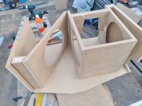
carbon fiber support (28 may) post 66 (better!!)
Add stiffnes post 69 (better)
Add "dust cap" stiffener... is it better?? Post 71
Background: After have been experimenting a lot with Servo subwoofers or MFB motional feedback in the 90-ties with success I went to dipole subwoofers and QUAD ESL 63 electrostatics (modified). Everything was fine until I realized that sometimes the ESL 63 playing on their own, had a magic in upper bass that can not be achieved with dynamic woofers... nope nix njet nej ikke.
8-10% distortion in a woofer does not blend well with QUAD or other electrostatics with <1% distortion in bass.
So only way out is to reduce distortion with a factor of TEN ! (Or go back to dynamic speakers..
😱 naa.. )
And here is how it is done
😎
Circuit: First I am using ACH-01 accelerometer and using Piratelogic Electronics EVE 2020 circuit boards which is wery convenient, however this circuit is not designed directly to fit ACH-01 so some tweaking on some values has to be done... also using CFB is changing frequency responce and phase a lot and on top of that dipole woofer, the frequency correction and phase response will be TOTALLY different from using the EVE 2020 the "normal way"
Which is to drive voltage amplifiers with Starbass accelerometers and small woofers in small boxes. If you want to do so there is another thread by chriscam on this forum.
So be careful, the manual for using EVE 2020 will not guide you the right way for this combination... but nice and easy.
We will get it working! And if you want to make it more easy use Star bass accelerometer. They seems to work great.
The benefits with MFB CFB and Dipoles: Using motional feedback to a Dipole woofer system is double or maybe triple compared to a closed box!
First: Distortion comes with longer strokes, which you have a lot more with dipoles than any other principle.
Second: Since the dipole compensation 6dB/octave raise the low fundamental tones, those fundamental tones has corresponding harmonics which will be raised several dB! If you play a 100Hz tone, the 2nd harmonic of this tone is also lifted 6dB, and worse... the 9th harmonic 900Hz will be lifted >18dB!!
Third: The 9th harmonic 900Hz is much more disturbing and noticeable since your ears are much more sensitive in those frequencies.
Dipole woofers are hard to integrate with low distortion midbass of an electrostatic speaker!
Reed the theory papers below and in nr 3, you find the benefits of combining CFB and MFB.
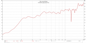
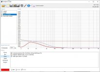
Distortion reduction and measurements part 1: Post 30 shows 2-3 times lower distortion, but it will be improved!
I have reached a more than ten fold reduction in distortion or 22dB in a prototype, and here i will guide you trough the building, schematics, measurements setup and all problems that you may face during the journey, I know, I have done all mistakes there is, and will try to cover them all.
SERVO subwoofers or MFB theory:
1.
http://rmsacoustics.nl/papers/whitepaperMFBtheory.pdf
2.
http://rmsacoustics.nl/papers/whitepaperMFBdesign.pdf
3.
https://www.rmsacoustics.nl/papers/Impulse Compensated Driver setup.pdf
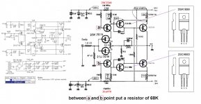
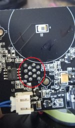
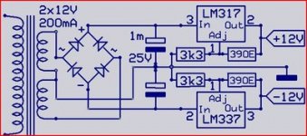
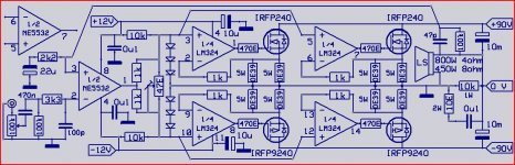
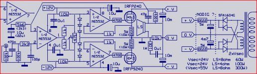
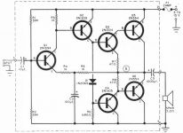
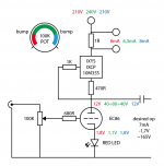
Input stage: The black and white part of the schematic is the accelerometer itself and the buffer J310 68k and 820 ohm resistors, mounted on the woofer, these are SMD components glued to the cone and hard wired under a microscope... crazy idea from the beginning, and even more stupid when the J310 was fried :-(
A part of the schematic EVE 2020.0 is shown, and a table with some assumptions. With ACH-01 you should add an impedance buffer see below.. (Starbass has a buffer already built in)
Updated 220511
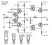
Accelerometer gain stage and loop mixer: Post 4 is misleading regarding J310 FET.. see picture below.
I have seen the application note schematic for ACH 01, but was mislead by another users design.
The ACH 01 shall have a negative bias as shown on the application note, to minimize distortion.
I will do a last try with ACH-01 Otherwise I buy ClingOn from Chris, and just get it working...
Big thanks to Robert-H Munnig Schmidt at RMS acoustics for explanation!! 🏆
Rob has achieved 30dB loop gain and 45deg phase margin... is that a world record? (some people is impressed by Messi and Ronaldo....)
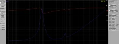
Stability, Phase margin, and OLTF measurements: Post 34
Stability at low frequency is achieved but at around 3kHz it looks really messy. So I am reaching out for any help, here.
Below is the input side of the accelerometer on EVE 2020 board. From here you will see that everything has to be made different with Dipoles.
How it should look like!
I did a last try with ACH-01, with stiffer carbon fiber support and new electric interface in post 66 and it works much better!

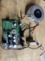
![20220616_132647[1].jpg](/community/data/attachments/972/972425-6a47b6f4fde792b8986dfd93d533fd8b.jpg?hash=ake29P3nkr)
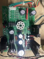
![20220616_132655[1].jpg](/community/data/attachments/972/972426-e3653fe0262b51100304a637db725c92.jpg?hash=42U_4CYrUR)
![20220616_132715[1].jpg](/community/data/attachments/972/972427-b14f7d0e02cc462348d8b015bfbaa84d.jpg?hash=sU99DgLMRi)


