27 + 47 SEUL amplifier project finished.

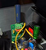
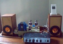
This project took a lot longer than I anticipated to finish but some life events got in the way. Part of the delay was fighting with finding good old stock globe tubes that didn't do weird things lol. Some of these tube weirdness issues made me question my design/other parts, but at the end of the day, the vast majority of the problems came down to wide sample variations/glitchy tubes, mainly with the 27 tubes.

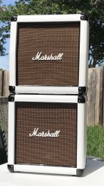
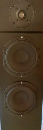
Anyway, I feel like this turned out looking very cool and was fun building what I consider a modern design, using high quality parts, with these ancient globe style tubes. I used a pair of Hashimoto 5-7k UL output transformers and it sounds REALLY sweet. Loads of detail and got it tuned to have a nice balance of solid bass and a tamed top end.

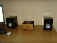
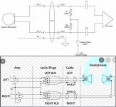
It puts out just under 1.5W into 8 ohm dummy loads but I swear listening to it on my RP600M speakers, it's sounds more like 2-3W. It does need a solid 2VRMS drive but any of my modern sources can handle that. It's just enough power for me.

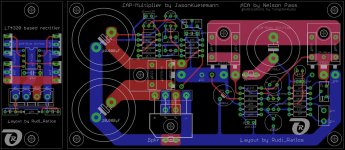
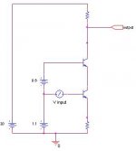
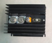
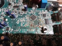
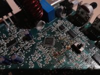
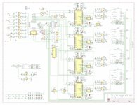
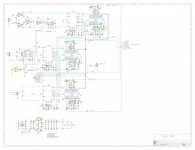
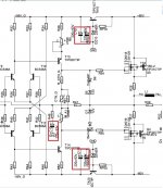
I did a complete build series of videos and here are the schematics and some pictures.

https://www.youtube.com/playlist?list=PLtEhh3UpOsiD-QbGfOhWdWjGsFb-4a4qL

47-amp-front.jpg


47amp-back.jpg47amp-inside.jpg47amp-side.jpg47se-final.png47SE-PS-Final.png

Aiyima d03 audio measurments

Hi folks,

I recently got Aiyima D03 and found it has bass drop.
I have BEHRINGER UMC22 soundcard and made some voltage reducer scheme for it (according to 3kOhm XLR input of soundcard): 20kOhm resistor in series and 2.7kOhm resistor in parallel (scheme was calculated for 11.34 volt and 16W output).
When I turn on Aiyima at 0 volume all is ok, but when I increase volume by 1 step, Clip lamp in UMC22 starts to flash. I suppose voltage still too high for it and I made a mistake in resistor calculation

Could you please help me:
1) Can I measure freq response of Aiyima, using USB audio as input? I use CoolEdit / Adobe Audition to watch my results.
2) What was my mistake in scheme? Reducer should compress signal to 0.75V, here is formula:
8e61b6e8e795d3dd40a23fb1a677495b.gif


where ZL is 3kOhm impedance of mic XLR input, Z1 is 20kOhm in series resistor, Z2 is calculated (in parallel) resistor, Vout is 0.775V, V1 is rms ampl voltage (2.82V for 1W @ 8 ohm load, 8.02V for 8W, 11.34V for 16W, 16.04 for 32W)

Differential transistors.

Have a Citation 22 where DC offset in the right channel is difficult to master. When turned on, DC speeds up to 1 volt to slowly creep down for many hours and when readjusting, i can keep it around 0. When changing the program source, it clicks into the right speaker at the same time as my DVM shows up to 1 volt and then drops slooooowly. The same result at the next switch-on and program change. Bias is OK according to the "book", so I guess the problem is on the pre-driver card, maybe the differential transistors in the right channel have given up? The question then is, which on the schedule are these transistors now? It is quite possible that there is something else that makes the DC offset go bananas when turned on, suggestions for sources of error are received with the greatest gratitude!
PCB-10.PNG
Citation 22.PNG

B1 Nutube vs Bottlehead Moreplay

After several years building speakers I am considering building my very first “real” piece of equipment and beginner friendly preamp.
At first it will be paired with a Quad 405-2, but dow the road the power amp section could/will change all depending on needs and time.
The Nelson Pass B1 and the bottlehead Moreplay fit the bill, and would like to hear if anyone oof you had the chance to compare the 2 sound quality and build experience wise.
Thanks

Grommes Precision S-100 info

Interested in applications of 6GT5 sweep tubes for PP audio amp design...
Not a whole lot out there- far as history of usage. Pic below shows what seems to be rare example-

Grommes Precision S-100​


I know Tony T has used these in SE design, and KodaBX has used them in PP...
Q's:
1. Are they a viable candidate to design low distortion good sounding 50w+50w in non parallel PP design? Or are they better suited for guitars?
2. Can anyone supply an audio amp schematic they've successfully built and recommend?
3. What kind of B+ is needed?

Thx,

Jim

Attachments

  • grommes.jpg
    grommes.jpg
    81.4 KB · Views: 145
  • grommes 100.jpg
    grommes 100.jpg
    25.5 KB · Views: 144

Too much gain - where to put a resistor divider?

I'm just wondering where the best place to put a resistor divider is in my system. My setup is that volume control is in software on my Mac Pro, which is my only source for everything. I have an amp which is 6SN7 into 2a3. The volume on that is perfect for my room - I don't need any more gain. However, I have a 2P29L line stage which improves the sound if I put in front. Problem here is far too much gain. 2P29L has a mu of 9. I really only want a 2x gain.

So looks like I could put a resistor divider in front of the 2P29L or in front of the 6SN7 or both, in fact. So where would be the most effective? The 2P29L is a better sound than the 6SN7. I may replace the 6SN7 with two 6AH4 or 1626 or something low gain like that. But for now it would be useful to put a resistor divider somewhere.

So where?

2P29L FBias resistor1.png2a3 + 6SN7 resistor.png

Suggestions for good quality tweeters

Hey all,

I'm looking for some suggestions for good tweeters similar to these. They, unfortunately, aren't shipped to my country, so I was looking for any alternatives that may actually ship to where I live (The UK). I'm looking to build a powerful directional speaker array built with 4 tweeters which would've been the aforementioned tweeters, so I was wondering if anyone had any suggestions for a machine like this?

Thanks in advance.

Help with Mission PCM 7000 CD Player Not Working Anymore

Hi Folks. I have a Mission PCM 7000 that I bought new in the 80s. It's been used very infrequently as I've ripped most of my CDs or buy digital downloads and stream the files to a DAC. But when I did try to use it recently, first the disc went in awkwardly and jammed the tray (maybe the CD wasn't in the tray properly), but the tray did open (pressing eject) and all that seems OK now. BUT every disc I try spins for a few seconds then stops, with the Disc and Error lights on in the panel. I took the lid off, and everything looks OK (mechanicals seem to work properly, no bulging capacitors on the boards). I also darkened the room to see if I could see any laser light when I loaded the disc, and saw nothing - but don't know exactly where to look or whether I should be able to see anything. Any advice to get this baby diagnosed or working would be much appreciated.

Yaqin VK-2100 mods

Have a Yaqin (Yaoin) VK-2100 hybrid. Really like it and squeezing all the mods in I can.

Taking suggestions for a matched quad of 6n1 or 6dj8's (would prefer the 6dj8's) to replace the stock Shauguan (or however you spell it) 6n1's. The stock 6n1's just don't seem very "good".... There is no manual bias adjust.

Would prefer NOS, but only can seem to find reasonably priced NOS in matched pairs...
Looking for something REALLY good in a matched NOS quad, or other suggestions.

Thanks guys!

MiniDSP 4X10HD modification and optimization

I bought a MiniDSP 4x10HD a while ago when I built the Linkwitz LXmini+2's and have performed some modifications and optimization.

Firstly I removed the output coupling caps and added wire links as the caps are electrolytic and not biased so will most likely be generating higher distortion. I have circled the caps in RED that I removed. Also before removing the caps I checked DC offset which was negligible. The other option is to replace the EC's with MKP's or other film caps.


After living with MiniDSP for a while I found that my MiniDSP 4x10HD was clipping at the input on SPDIF and AES but not TOSLINK. To fix this I have lowered the input gain to -6dB and increased the output gain +3dB across all 4 outputs.

What I did was to decrease input gain until loud passages did not clip the input monitor, then I increased output gain until the subwoofer just clipped and backed off until no clipping occurred, then adjusted the other 3 outputs with the same additional gain as the subwoofer.

I plan to bypass the internal output DAC's using the I2S header on the PCB at some point in the future, but the shortage of components has made sourcing high quality I2S / DAC harder to come by.

IMG_20220205_093512505.jpg

Optimal vent length

I'm in the process of building a 3-way speaker. The ports I'm using are somewhat tapered, which makes it harder to determine the correct length. I know such ports can be modeled in Hornresp, but I don't know how. Also, as Troels notes, the required port length to achieve a desired Fb can be significantly shorter than the calculated length (depending somewhat on the amount of damping material).

My plan of attack for now is to make multiple nearfield measurements (port + driver summed). Starting with the port a bit longer than the calculated length, and shortening it 5mm for each consecutive measurement. This approach seems labourous to me, I hope there's an easier way to determine the right port length based on just one FR & Z measurement.

heat sink temperature rise above ambient

I'm confused about heatsink C/W values. I've used online heatsink size calculators and two of the required inputs are ambient temp and max temp. I've input 25C for ambient and 65C for max temp, thinking that equals a 40C rise above ambient. Heatsinkusa says their approximate °C/W/3" values are based on natural convection and a 70C temp rise above ambient. Another heatsink manufacturer says their approximate °C/W/3" values are based on natural convection and a 60C temp rise above ambient. Based on that it seems the 70C and 60C above ambient would allow the chip temp to get 20C to 30C hotter than my calculator inputs. What am I not understanding?

CMRR of LM3886 vs LM4562 - which one is better to choose as a summing amp?

Hello everyone!

I have been reading more on the instrumentation amp configuration theory and from what I understand CMRR or common mode rejection ratio is an important measurement to pay attention to when choosing summing difference amp IC (U3 in the schematics below).

inst-amp.PNG

Now, when designing amplifier with differential signal inputs (or balanced inputs) there are a few options. One configuration could be to use LM3886 as U3 summing difference amp and to use two LM4562 as an impedance buffers U1 and U2. In such configuration the extent to which circuit is able to reject common mode noise and interference is defined by LM3886's CMRR. The datasheet provides it in Figure 48 on page 16:

lm3886-cmrr.PNG

Another configuration can be to use LM4562 as a summing difference amp. It's CMRR is provided in the datasheet on page 18:

lm4562-cmrr.PNG

Comparing those two graphs it can easily be seen that LM4562 is better option for the summing difference amp U3.

With that said, I have a few questions:
  1. If I were to use LM4562 as a summing difference amp, how would I feed signal into LM3886? Non-inverting or inverting configuration?
  2. Am I missing anything as far as differential signal extraction?

Thanks in advance,
Pavlo

Headshell for my Amp

Made this for my Marshall Haze 40c. Now I can use it with my 4x12 or recently recovered mini stack shown here.

Attachments

  • B7FFAADC-68C5-47E6-A61D-3AC7BB5BBC9E.jpeg
    B7FFAADC-68C5-47E6-A61D-3AC7BB5BBC9E.jpeg
    257.3 KB · Views: 63
  • 7CFEC6AA-2004-4DA2-A693-F797183B04BF.jpeg
    7CFEC6AA-2004-4DA2-A693-F797183B04BF.jpeg
    197.3 KB · Views: 64
  • 8D78C0C3-7100-455C-A10A-E67E71E7A951.jpeg
    8D78C0C3-7100-455C-A10A-E67E71E7A951.jpeg
    735.9 KB · Views: 114
  • 6D180DDB-3B15-4217-9202-D190FD425132.jpeg
    6D180DDB-3B15-4217-9202-D190FD425132.jpeg
    575.4 KB · Views: 64

considerations on the sonic signature of low noise, high PSRR LT3045 regulaltor

Thought about to make this to a dedicated topic instead of cluttering somone else' thread.
Background is, that I'm frequently in need for some upgrade of rails regulators. Trying to adapt the usual and ready available shunt and series suspects, often did not necessarily lead to the desired results.

Though the well documented specs on load and line regulation would indicate them as no brainer, the sonic signature inherent to any of this device gets imposed on the sonic signature of the stage to be fed.
On sensitive stages the sonic signature of the regulator even begins to dominate, which of course is not any desirable.
So what I'm covering here is focused to the aspect of rails being part of the signal path, a different point of view, usually not that widly noticed.

I went with a LT3045 board I got from here:
LT3045-M Ultra Low Noise LDO Voltage</br>Regulator
They are of a nice built, using good parts, and surely the designer has studied the AnalogDevice data sheet to get the best out of it, so its a solid starting point.

Inserting the +15V configured board straight away in what I will call my test setup (basically a constant current dual FET input stage), did not bring up satisfying results.
After some experiments with RC filtering of the output of the LT3045 it did show up, that the capacitors used do have a fulminate effect on the sonic signature of the amp stage to be fed.
I did try tantal, Nichicon Fine Gold and the green bipolar ones from Nichicon. Very distinctive flavours easily to distinguish.
The RC filter I varied from 150ohm / 100uF to 1.5ohm / 47uF.

When gradually lowering the R of the filter it became apparent that the LT3045 input capacitor (47uF tantal) at the board at hand becomes sort of a bottle neck. Most probably this is also the reason why just inserting the board straight away did not deliver sound wise.

So the next step was to pimp the LT3045 input with a 1000uF Nichicon FC decoupled from the PS with a 1.5ohm resistor, what in fact did turn out pretty well.
With that out of the way, as to now to me the best combination was the Nichicon bipolar at 47uF / 1.5ohm.
The Fine Gold was overly glossy and didn't went down to the bottom.
The tantal suffered in musicality but was by far the most stringent down low.
The Nichicon bipolar overall was the best compromise so far.

This was just a very quick rush through the topic of rails being part of the signal path and I am looking forward to also try some other Pana and Nichicon lytics I await in the ideal test setup I currently have available by accident. All lytics I usually parallel with MKT and silver MICA, so I did it here as well.

Regarding the basically excellent LT3045 I would love to hear your findings on its sonic signature and the modifications you possibly did to deal with.

Attachments

  • LT3045_board5.JPG
    LT3045_board5.JPG
    290.2 KB · Views: 655

How to design a cross over for cheap speakers.

Im sticking this in a section so nobody gets upset. About posting in the wrong section.
Here is my question. How do I create a cross over with zero info on the speakers.
The issue is if you want to get speakers with all the tech specs. They cost a lot. Im talking more than 3 times the price.

Im building my speakers using el-cheapo speakers. Which come with Zero tech specs. You go to a shop. You decide what size you want and what watts.
They test it for you. That's it. I still think a good cross over would help them sound better.


Im starting out in this as a hobby. I have no idea what I will like. What will work. What will not.
So Im not going to drop a lot of money into some drivers I may like or not like. Because I have no idea what size of woofer will satisfy my need for heavy bass.
What size of mid will match the woofer. I still need to see what size speakers work. Will an 8 inch woofer work for the kind of bass I like. Or do I need a 12 inch woofer. If I use a 12 inch woofer how large should my midrange speaker be.

Have been going thru speaker box designs on various sites seeing how they combine speakers.
All I want is nice clear music with good bass. My amp will put out about 60-70 watts RMS. They claim 200 watts per channel.
Im lost and need some advice.Have purchased 3 amps. and 3 preamp / tone control boards and a transformer. I have Proteus and can test various design ideas in simulation.
Even some basic advise like for a 2 way use this cross over for your tweeter and this for you full range. And for a 3 way do this. Or a way for me to figure out the tech specs I need.
I have a function generator, a scope. So was thinking what if I do a freq sweep and see where the speaker starts to work and stops to work. Could I use that to build the cross over.

Friends have donated a lot of their DIY speaker projects. So far the best is a 2 way with a peerless tweeter with a 8 inch full range boston acoustics. It sounds amazing. But zero Bass.
Im thinking if I build a 2 way it may help me get some bass out of it.
Or should I just add an 8 inch woofer. Sorry for rambling.

Premium ACA with CapMX PSU

Gentlemen,

I have been asked to offer another round of groupbuy for my layout of Nelson Pass ACA amplifier - modified by TungstenAudio.
I will do - but: be sure - this will be my last contribution to the ACA.

Find attached an image of my PCB offer.
It contains of:

- a LT4320 based rectifier on the left side of the image
- Nelson Pass' ACA (with slight modifications done by TungstenAudio), on the image right side
- being driven by JasonKuetemanns CapMultiplier
- if you will ever read Rod Elliotts recommendations for a (small) ClassA PSU: here we are!

I will offer you 2 pairs of my PCBs (2xLT4320, 2xACA) as unregistered mail for 20€.

Tell me if you like to have.
Best regards - Rudi

P.S.: I am currently busy building a new desktop-PC for my own needs. It will consist of:

- BeQuietPure 500 Case, MSI X470 Gaming PLUS Mainboard (from time to time I like (?!) to play "Age of Empire" or "Stronghold", or even GTA)
- 16GB PC3200 DDR4 RAM, Radeon RX580 8GB graphic card, ..

Please have a look at my setup on image2.

An USB attached ASUS "soundcard" misses any heights!
The onBoard RTC892 does not " sound any better".

How shall I go on? Do you have any recommendations?

Attachments

  • Last_ACA_contribution.jpg
    Last_ACA_contribution.jpg
    240.1 KB · Views: 2,340
  • ACA.JPG
    ACA.JPG
    539.1 KB · Views: 2,228

Speaker watt mismatch in 3.5 way

Hi,

Thank you for helping me.

I've searched but apparently don't know the right way to search for the answer. This has to be a common design situation.

I'm building a 3.5-way speaker and trying to select the drivers.

The woofers are 200-watt RMS. I have a mid that is 150-watt RMS. And the tweeter is 25 watt RMS.

What am I supposed to do to integrate that 25-watt tweeter into the mix without risking damage to the driver?

I've never built a crossover before, but am learning.

Thanks,

Dan

Very inexpensive 15" open baffle woofer

Run across some interesting woofers for open baffle use they are also very inexpensive. https://5core.com/products/pro-audi...b-woofer-loud-speaker-driver-full-range-8-ohm I actually run across these by accident. The QTS 1.29 the FS 44 HZ very close to the Eminence alpha 15" but these speakers have a 60 oz magnet vs the 25 oz magnet on the alpha's. These 5 core 15's are also available on eBay for $54.49 each free shipping $47.41 each free shipping if you buy four. Has anyone in the forum used these drivers for open baffle? Someone could build a pair using two of these per side for under $200.00 that is a steel. Hopefully I will have these mounted in a baffle and give them a listen soon. I have never heard open baffle speakers before hopefully these sound great.
PHOTO_20211218_005544.jpg
PHOTO_20211218_005622.jpg
Screenshot from 2021-11-30 00-36-47.png

Mini-console based on CHR-70 gen1

Mark suggested that I chronicle my mini-console project. It is based (speaker wise) on the first generation CHR-70.

Some background:

It is my plan to make a special gift for each of my eight grand children as close to the high school graduation as possible. The first was a guitar amp for my grandson based loosely on the Marshall 18 Watt with a modified plexi front end. The project I am discussing here is the second project which is a mini-console iPod dock for my grand daughter.

The concept is to take the vacuum tube console stereo concept and shrink it down as small as possible while still retaining full spectrum high quality sound but still have it portable enough to move from room to room. It is not to be a portable in the sense of a ghetto blaster but in the sense of easily transportable. It compares to the traditional iPod dock in much the same way that the original Compaq Luggable compares to a notebook.

The design is still in flux and has been discussed in several other places in one form or another.

Electronics and some amp build here...
http://www.diyaudio.com/forums/tubes-valves/180141-mini-console-schematic.html

Some Layout possibilities here...
http://www.diyaudio.com/forums/tubes-valves/176015-layout.html

Laborious process of settling on an approach here...
Serious design effort begins on mini-console project - AudioKarma.org Home Audio Stereo Discussion Forums

In the end I decided on a SE KT-88 amp in UL mode with Schade local feedback. The Power amp has been built and has been used in testing various speaker possibilities.

Now for the speaker part:

I started by putting the drivers in a hacked up Onkyo cabinet which is very small and sealed just to get an idea of the sound and capabilities.

attachment.php


They sounded quite good with exceptional imaging and plenty of volume. The mixer that I am using for testing does not have enough gain to drive the amp to full output but still provides very loud listening levels.

attachment.php


It was lacking in bass so I looked into doing a ported box to get down to my goal of usable output to 40Hz. It looked feasible...

attachment.php


attachment.php


So I built a test box. (To be Continued)...

Attachments

  • SmTestMount.jpg
    SmTestMount.jpg
    82.7 KB · Views: 1,143
  • RespMarkCHR70.png
    RespMarkCHR70.png
    9.2 KB · Views: 766
  • RespMarkCHR70Ported.png
    RespMarkCHR70Ported.png
    11.8 KB · Views: 767
  • SmPAworking.jpg
    SmPAworking.jpg
    108.3 KB · Views: 747

Free M&K 12" subwoofer cabinets

Free M&K 12" subwoofer cabinets. Maple veneer, new/unused. These were from an inventory buyout about 10 years ago. Local pickup only in Orange County CA. 3 available. I have a few grills for these too.

Attachments

  • IMG_20220619_105613891_HDR.jpg
    IMG_20220619_105613891_HDR.jpg
    500.4 KB · Views: 102
  • IMG_20220619_105618716_HDR.jpg
    IMG_20220619_105618716_HDR.jpg
    491.4 KB · Views: 103
  • IMG_20220619_105746067_HDR.jpg
    IMG_20220619_105746067_HDR.jpg
    772.3 KB · Views: 100

Audio Static ES100 replacement transformer and replacement service for mylars

Hi all,

please help.. 😱😱 During the refurbishment project I managed to damage one of two transformers windings on the ES100 driver. Does anyone know the original specifications or suggest transformer replacing all of them?:scratch:

There's also a hole in the mylar so I need to get them replaced as well.. I already reached out http://loudspeaker-repair-service.reromanus.net/ but had no answer. I already removed the panels from the sides and no I didn't made the hole during the removal 😉

Thanks for advance!🙂

Best

Jarkko

Attachments

  • es100 tranformer.jpg
    es100 tranformer.jpg
    348.7 KB · Views: 166

Low voltage tube based supply for turntable?

Hello, everyone. I was wondering if anyone here has any experience building a regulated power supply using EL36 tubes and a 5AR4 rectifier, as in the Brinkmann Ront II PSU? The output of that supply is DC 24.5V, approximately.

There is very little information on the web about this PSU, other than it uses the 5AR4 as a rectifier to supply 80V to a paralleled pair of EL36 tubes that are used as series pass regulators. There are some common mode chokes, and some solid state bits that control the tubes- creating a reference voltage, and receiving feedback to set the output voltage precisely. I have a good idea on how to build it, but figured I would ask up here first.

Ultra lightweight speaker for PA and party

Hi. I'm looking for help with designing an ultra lightweight speaker system for music performances. It needs to be small and light enough to carry by hand over long distances and to transport on buses and trains. Yet it needs to be loud enough to fill a hall with 100 people. There may be lots of different venues and mains power is always available. The music will be folk and MOR, so not much need for heavy bass. There will also be vocals from a mic which need to be heard with good clarity. I know, it sound impossible.

My thinking so far. Weight is the killer and I have to save every gram I can. Loudspeakers are heavy, so the fewer of them the better. Ideally I'd prefer a single full range driver for the whole system, say 8 or 10 inch. And it needs to have high efficiency so the amp can be smaller and lighter. Obviously the amp should be class D with a small switched mode power supply.

The cabinet needs to be small and light, both of which are enemies of good sound quality. It may be OK if bass response is lacking, provided people can hear the music and vocals. I'm thinking of using quite thin plywood, say 6 or 8mm with lots of internal bracing to stiffen it. The overall shape would be trapezoidal to minimise resonance. I'm not sure what internal volume to use. Ideally, not much more than the speaker itself.

I've not much experience with speaker design. The last cabinets I made were in 1970 from a Wharfedale Unit 3 kit. I'd welcome suggestions on the best way to proceed and recommendations for drivers and amps.

Cascodes- the truth is out there...

I've just came up to an idea about cascodes, precisely about some threat in circuits with casodes, like cascoded voltage amplification stages or cascoded current sources.
I feel there is a lack of theory concerning cascodes, namely there is no explaination why cascodes don't always sound better, despite of technical advantages (reduced Early effect and Miller effect).
Some just state, that simpliest circuits sound best with no further technical explaination, others prefer cascodes because of theoretical advantages disregarding real listening tests.
The only technical drawback being an ultra high output impedance.?? I don't believe this matters so much.
For start I attatch cascoded voltage gain stage to visualise.

to be continued...

Attachments

  • casc.jpg
    casc.jpg
    9.6 KB · Views: 2,014

Constant low pitch sound. Kenwood KA-6004

Hello, Can someone help please? I have a constant low pitch sound on my Kenwood KA-6004. This sound increases/decreases as I turn the volume up/down. This happens even if disconnect all inputs (no AUX, Tuner, Phono etc... are connected to the amp). This low pitch sound is also heard through my headphones (with both speakers A and B buttons switched off).

If I switch the "Normal/Separate" button at the back of the amp 'Separate' the noise cannot be heard.

My expertise is very limited and I am hoping someone can give me some pointers on a few easy/initial tests I could run before I take my amplifier to the repair shop.

Cheers,
Marc

Why this shape

New to planar magnetic drivers and I am finding them very interesting, and since I am working on an loudspeaker which take advantage of dipole property's, planar magnetic drivers is kinda a necessity. But why the (mostly) rectangular shape, does it have a property favorable over round ?. Is say the vertical propagation of an elongated driver more desirable than its circular cuisine ?
If anyone has a take on this, come forward 🙂

Active discrete Baxandall Tone Control

Based on famous principle of Tone Control by legendary audio engineer Peter Baxandall , After messing around in breadboard , I successfully designed a decent Tone control for Single Supply use for TPA3118 , TDA7297, TDA7376 . Now many people will Why go discrete when opamps are available . Well NE5532 on rail splitter did so up some noise on my CRO.
It uses very easily available components
I want to see how it performs on KSC1845 but for now i have used BC549B for buffer stage and BC549C for Tone Stage.
https://i.ibb.co/NjhPBRr/IMG-20200627-214541.jpg
Please have a look and any recommendation/criticism is always welcome to me.
Hope I spent my LockDown well on a fun little project
Pots are 100k each , Lower is treble whereas upper one is bass.
Edit: I fixed Typo and Schematic , Updated information about pots

FS 4x Acoustic Elegance TD15M-8 non-apollo

I bought these drivers several years ago from a forum member. He used them for a short time before selling them to me. I mounted two of them in a cabinet with a SEOS waveguide and used them for about 2 months before my wife made me move them to storage because they were too big. The other two have been sitting in a box in storage the whole time.

I am asking $250 plus shipping for each driver. They will be individually packaged well and will ship from 29631.
  • Like
Reactions: tomtt

Celestion Ditton HF2000 replacement tweeter (again)

hello all,
ive have just recapped my celestion 66s and had a supposedly good matched spare pair of HF2000 measuring both at 4.5 ohms.
after recapping i thought id bung them in,too my surprise they sounded good but where lacking in hf,they just weren't as loud as the original tweeters.
it turns out they were from a pair of B&O 5700's which use the same hf2000's and mid driver MD500.

I removed those hf2000's and put the original ones back in and everything returned to normal!
the only downside to this is one measures fine,the other measures 9.6 ohms.

id like to replace them with something more modern and it seems from hours reading that the Seas 19TFF is a good drop in replacement.
there are lots of threads on hear with conflicting advice regarding what to change the hf cap values too and they are all very old threads.
i wonder if anyone recently has done this mod and what they used cap wise?

here's a pic of the newly rebuilt crossovers,caps were changed like for like.
An externally hosted image should be here but it was not working when we last tested it.
[/URL]

the B&O hf2000's
An externally hosted image should be here but it was not working when we last tested it.
[/URL]

  • Poll Poll
Why No Dipole Subwoofers for Pro Audio?

Could dipole subwoofers be practical for outdoor use?

  • No

  • In some specialized cases

  • Yes


Results are only viewable after voting.

Just wanted to get the community’s thoughts on why we don’t we see more (any?) dipole subwoofers in outdoor/large-venue pro audio.

To ground the discussion, here’s a basic example:
A 21” subwoofer driver mounted in the center of a round, 8’ diameter sheet of something sufficiently stiff (maybe sandwich composite to save weight). I.e. open baffle.

Siegfried Linkwitz (RIP) has a great page on this, but to summarize, a dipole’s “…frequency response has a characteristic 6 dB/octave roll-off towards lower frequencies…”. The larger the baffle, the lower in frequency this roll-off begins. Dipole’s have a figure-8 radiation pattern, but this breaks down above a certain frequency, so in practice dipoles have a limited bandwidth which is generally fine for a subwoofer.

This chart shows a case that is very close to my example (where b=4.57a):

Image.png

So for my example, ka=1 would be about 200hz. Compared to an identical driver in an infinite baffle (i.e. monopole), the response would be the same at about 60hz, and the dipole would be 6db lower at about 30hz. The dipole has fairly consistent figure-8 dispersion up to 200hz (30-200hz is about 2.74 octaves). Please jump in if my math is wrong here.

I see a few big reasons for using dipoles instead of traditional sealed/ported/horn-loaded subwoofers:
  1. Portability: While you need a huge baffle for low frequency extension, if you could detach the driver, and stack the baffles in a truck, they would take up much less volume than traditional subwoofers
  2. Directivity: Cardioid subwoofers are already used to great effect in pro audio, often at the expense of efficiency. The dipole pattern offers an even tigher pattern which could make it easier to ensure consistent bass coverage over a crowd.

Potential downsides:
  1. A given driver would not be able to produce as much low bass as the same driver in a ported/horn-loaded subwoofer. But this could be mitigated by simply using larger cones/ more drivers. There is no enclosure so you’re not contrained by enclosure size. Surely the increase in driver cost would be less than the money saved through increased portability.
  2. There is a back-wave: This is prevents use in small/medium indoor venues.
  3. The baffles would block view of the stage. The baffles could be clear (plexiglass), or even covered with displays.

I know that frequency response is not equivalent to efficiency, but wanted to explore a simple example. I would welcome any comparisons between sealed/ported/horn-loaded subwoofers and dipoles.

Thanks for reading, and excited to read what everyone thinks.

Opamp Labs 440C -- 50W -- never used

Opamp Labs 440C audio amplifier -- or use it as a subwoofer driver or table shaker (DC to 25kHz). Manufacturer lists it for $125 -- you can have it for $10 plus shipping.
Link: https://www.opamplabs.com/products/logic-module-plug-in/d-c-power-amps/440c.html One unit only. I think I purchased it in early 1980's:

Attachments

  • IMG_6025.JPG
    IMG_6025.JPG
    129 KB · Views: 122
  • IMG_6027.JPG
    IMG_6027.JPG
    118.8 KB · Views: 131

BG NEO 10 reborn just better and of unoptanium.

PS Audio has developed an new high end speaker and to get the best sound, have they decided to use the great BG NEO 10 driver, but since it is not made anymore, have they decided to make there own version with some improvements.

I contacted PS Audio sale and what a polite service, but unfortunately did they reply that Paul (CEO) did not wish to start up selling, due to the extra work with distribution, guarantee and so on.

Now is my question, do you think that we can change his mind, maybe by a group buy or by letting one of us, be the internal distributor?

MTM vs coax for point-source design

I believe point-source together with acoustic centers alignment are very important things for speakers hi-fi playback. Without them I believe there is a cap - it can be good but not very good.
I would like to ask for some acoustic theory advice (and practice if available) about comparing two design options to achieve at least some degree of point-source. One obvious is coxial speaker but there is limited choice of them and typically they are rather costly. The other option is MTM and that’s where I am asking for advice and support in comparative analysis. I have read coaxials in terms of point-source characteristics are much better than MTM. I understand the main thing is lobing. But does it apply irrespective of how this MTM is actually built in practice ? I was thinking about two 3-inch fullranges and a ¾ inch tweeter. If it is a no flange build then I can place the mids as close as 3 cm apart.
Their size is around 7cm which gives us 17cm altogether which is almost the same as a typical coax driver with an 18cm midbass. And I have also precise control over the acostic centers alignment as I can put the tweeter in between a few milimeters to the back.
Are there then still significant acoustic advantages of these two options – an 18cm coax and a 3” +3/4” MTM ?

Help me understand AMTs

So, I'm looking to build a desktop 3-way and, for some reason, I've always been fascinated by AMT's. My design is still very much in the beginning phase, but I'm thinking a Dayton Audio RS100 with a Dayton AMT Mini-8 or (more probable) a Dayton AMT-2 with very shallow crossovers (since the RS100 has a lot of highs and is often used even without a tweeter). The thing is, I hear great reviews about AMT's, but their frequency graph kinda.....well, kinda sucks even compared to a $20 Dayton dome tweeter. How is it that AMT's are often described as "open", "crystal", "smooth", "invisible", "airy", "transparent", and are generally (seemingly) considered a significant upgrade over cheaper dome tweeters when their response is "meh" at best?

Matching MOSFETs

Not only do I want to match MOSFETs, I want to make a MOSFET checker/matcher rig. I would use it to test and match mostly older Hitachi MOSFETs, Eg 2SK134 and 2SJ49. Dick West used to be able to match and check them for me. He has sadly passed away last month at 82 years old.
http://www.diyaudio.com/forums/solid-state/31131-hafler-dh-200-220-mods-111.html#post3415258

He had a Hafler MOSFET Checker/Matcher device.
44293d1116021389-8-hafler-hitachi-mosfets-4ea-2sj49-p-2sk134-n-haflermosfetchecker.jpg


Anyways, I would build a Nelson Pass jig. I assume in that Hafler box there was a built in multimeter and thats what the needle meter is for. The MOSFET's Gate-Source Voltage is +/- 14V, so I gather that my power supply cannot be higher that + or -40V. And I can't draw more than 7A, or I will destroy the MOSFETs.

2SK134 pdf, 2SK134 description, 2SK134 datasheets, 2SK134 view ::: ALLDATASHEET :::

An externally hosted image should be here but it was not working when we last tested it.


I assume the little rotary selector (Gate Level) 0-7 is just connected to a bunch of resistors (R in the schematic above) to allow different amounts of current to flow though.

Is this right?

Also, here is Mr. Pass's article http://passdiy.com/pdf/matching.pdf

I really want to build a Hafler MOSFET checker for my own use instead of finding someone to test them for me. Hafler never released schematics for their checker unit, probably as it was used internally only. I have some questionable MOSFETs from some old Hafler amp, and besides testing them, want to match and grade them to finish the other channel in my XL-280 conversion into a Musical Concepts PA-4 amp.

Pioneer CS-T6000?

Long time reader first post. Not sure if this is in right spot.
Came across a pair of Pioneer CS-T6000 speakers and picked them up on the cheap to go with my parent's old pioneer system that's been sitting in the garage without speakers so.... Anyway, I can't find anything on them at all. They sound good for 40year old. Is anyone familiar with them?

5.1 channel preamp version 2

3 years back I did a 5.1 channel preamp for TV audio. It uses 3 JRC NJW1119A 3 band tone
control ICs, along with 3 PGA2311 stereo audio control. These chip are all analog with digital
control. If you want to change center frequency of the tone control you need to replace resistors
and capacitors. I also included L & R mono mix and switching to create a center and sub feed
from plain stereo L & R. Control was from an Arduino covering IR remote and local shaft encoder
volume/mute This is all on a 104 x90 mm 4 layer board from JLCPCB and cad work with KiCad 5.x.
That extra 4mm added $27 to the PCB charges but it was still so cheap i didn't care. It works very
well so being DIY, it's time for version 2. This time it's 99.5mm x 89 mm.

Version 2 adds an 8x8 input crosspoint for channel routing. I would prefer Analog Devices for this
but they had been made of unobtainium for many months so instead I'm using a slightly inferior
MT-8808. The PGA2311 gain controls are sill present but at the end of the chain to keep noise down.
The magic is now with ADAU1701 DSP chips which can be 5 band parametric EQ or interface with room
EQ wizard. I will be using a common oscillator for all 4 DSP chips. Since EQ changes are very rare, the
DSPs can all do self boot but it requires the I²C address to be 0. I have an I²C selector to talk directly
to the DSP chips like is done on the Eval board so the local I²C can stay at 0 for self boot. Logic level
translators should prevent damage. Master reset in included. I have the Eval board from Analog Devices
and the tasks I want are do-able. Control is out of Arduino range and will likely be from Raspberry Pi,
maybe Pico or 4.

Power supply is from a 12V external SMPS to a DC-DC converter for the OPAMPS, matrix and gain controls.
The 3.3 Volt DSP supply is an SMPS in a TO-220 footprint, same for the control 5 Volts. What I want here
is take a look at the new version and see if I have done some really dumb mistakes.

The original version 1 is here along with the new version 2.

Attachments

  • five_one version 2.jpg
    five_one version 2.jpg
    470.4 KB · Views: 157
  • five_one version 1.jpg
    five_one version 1.jpg
    285.7 KB · Views: 153

properly grounding outdoor antenna

I have an antenna mounted on a pole to the side of our house. It is grounded to a rod pounded straight into the ground at the base of it. It is my understanding that the ground there has to be connected to our house ground.

Is anyone familiar if that can just be connected to a water pipe in the house? Or does it have to go back to the ground connecting at the breaker panel? Any special method for entering the house or just drill a hole at the attic level?

Open Baffle Build: I can't go back to closed speakers...

Hey everyone!

Here's a little story about how I became infected with the open baffle virus.

A couple of years ago I bought some Telefunken (DEW / Magnetfabrik Dortmund) 10 inch (25 cm) drivers for €3 on a flea market. It's an old paper driver with a whizzer cone. Can't find any info about them though. I never got around to do anything with them, though the idea of building some open baffles for them has been in the back of my mind ever since I've had them... Weird speaker designs intrigue me.

After years of gathering dust on the shelf I finally built a pair of open baffles for these drivers yesterday. The design is based on the design of the Betsy by Caintuck Audio. Don't look too closely, they're quite rough and they're actually not finished yet. It started as a quick and dirty project. 😉
1649795513888.jpg


At first the drivers were very shouty. It was so bad, I considered giving up on the project, or at least, the drivers. But then I read something about putting a resistor in series with the driver, so I added a 1,1 Ohm resistor in series with the driver. This fixed most of the shoutyness. Magic!

When I first started listening to them, I wasn't impressed at all. But then I started noticing new things and I started playing with placement, and well... I've been listening to them this whole afternoon!

There's so much wrong with them. They're still quite peaky / shouty and there's no output below ~80 Hz and I guess above ~12 KHz, but I love the sound. I've had Victor Wooten (especially The Vision) and Take 6 (Sweet Georgia Brown) on repeat for at least an entire hour. High Water Everywhere (live from the Royal Albert Hall) by Joe Bonamassa suddenly came to live. There's such an immense sense of space and depth. Instrument separation and definition in the lower frequencies is unmatched. Hearing an open baffle speaker for the first time really is quite the experience!

On to my problem - after putting them away again and putting up some music on my regular closed box speakers I miss the transparency and the soundstage of the open baffle speakers... The sound of the speakers I've loved for so long seems dull, dry, I don't know... It's missing something - room interaction? Space filling sound?

Has anyone else had this experience after hearing open baffle speakers for the first time? And how do I get rid of this open baffle disease... 😵

Chip amp power single supply

Hi!
I apologize in advance for bad English. I need a power amplifier chip with a single supply.
Power battery 12v 7a/h
Technical specifications speaker
POWER HANDLING (RMS/MAX.) 100 / 180 watts
IMPEDANCE 4-8ohms
SENSITIVITY (2.8V/1M) 91 dB
FREQUENCY RESPONSE 32 - 32000Hz
I am considering tda8560. But perhaps there is something better? Interested in sound quality. Thank you!

How to convert, if possible a headphone from unbalanced to balanced?

Please don't tell me this has already been discussed, because the first thing I did was doing a search with this exact question.

Is it possible and how it's done, through DIY, to convert a regular unbalanced headphone or earphone to balanced?

So I made a search, and went to have a look on how it's done on balanced microphones and on balanced headphones.

It seems the ground is floating on both cases and you three wires for each transducer: positive, negative and floating ground. The key is to keep all these three separate all the time.

This interest arose because I bought a Fiio Headphone Amp, and it has a balanced output. So I would like to listen to it, not willing to buy a new headphone for that, just re-wiring one onto balanced output.

Has anyone re-wired their units?

Attachments

  • balanced.jpg
    balanced.jpg
    46.2 KB · Views: 723

Philips CD460 tray not opening

Hi

After some changes in the system I though it would be nice to hear how my vintage Philips Cd460 with Pass D1 IV converter does in the updated environment.
I have always found it very natural, unobtrusive, relaxing sounding. (for those who do not know this player - it is a reasonably cheap player from the last century with TDA1541 DAC and CDM2/10 drive. I added a separate regulator for the digital filter - this improves a lot (some people convert to NOS here I didn't); I tried a number of alternative analog stages there instead of op amps; finally I settled for D1).

Anyway, the player always had an issue with the CD tray opening.
It always needed some help. Closing was never an issue. It closes like a hurricane.
So yesterday it just refused to open the CD tray. I opened the chassis and started helping it even more (pushing the wheel etc). Sometimes it helped a bit sometimes not.
Again closing no issue whatsoever. I googled a bit. Seems like people advise to replace the tray belt (still if the belt were bad why would it close nicely?).
Anyway I have another Cd160 which seems to be exactly the same player as CD460 but in a smaller box. Even the PCB is the same - the interior of CD460 has more voids which can be filled with my stuff.
The CD160 opens and closes nicely. I thought first I would take the belt from cd160. Then I though why not the whole drive with servo and all.
So that is what I did. And it behaves exactly the same in the CD460 body as the other drive. Put it back to 160 and everything is fine.

Has anybody any clues?

FS: Nomex 164 used drivers

2years old and not abused drivers only kit. 4x peerless hds p830875 and two scanspeak d2608 - 9130.
Sell for 360eur obo, ship to Europe included. Other Countries ask quote. No official packing but will install protective removable grills to protect. Partial sakes might be considered.
If I sell the drivers will sell the xover as well. So if you have appetite for it please write. Thanxs

Attachments

  • 20220614_151500.jpg
    20220614_151500.jpg
    139.6 KB · Views: 125

DBX 1215 question

Hello All,

Recently had reason to purchase a DBX 1215 graphic equalizer. While I am quite happy with the addition as it certainly helps music sound better at the lower sound levels I use more nowadays, I would like to upgrade it a bit. Have been unable to get a schematic from the company or find one online.

Would any of you have the schematic for this unit or know where I can find it?

Looking at replacing the cheap RC4560 opamp's with LM4562's and working on bettering the power supply a bit. I do know the LM4562 uses a bit more power than the TC4560 chips, so do want a better look at how the supply is designed and how much headroom there is for current supply. Design seems to be pretty decent with the limitation being the cheap op amps used.

Regards,
Greg

CD player digital output

Hello all,
I have a question from the digital output of my CD player.
The CD player is SAT CD Fix which has dead right channel. I suspect the output buffer opamp is broken but not sure. The player has also AES digital output(XLR connector). Can I see with my scope if there is the right channel in the digital signal or not? If there is right channel working I could buy a new DAC as they have developed lot after CD fix was made.
Also if somebody has the schematic of that player, I would be very happy. Thanks!

Bryston 1b fix questions

Hello,

Wonder if any of you have seen this. I am being cautious but here is one of the issues (there are a few others).

The schematic shows two filter caps at 3300uf on my 1b BUT in the actual preamp I find two 1500uf caps. bryston.com/PDF/Manuals/1B_MANUAL.pdf

So, my question is, does Bryston make changes like this in production or do you all think it's a bad fix from a previous owner?

More important should I use the 1500uf caps or put in the 3300uf to be accurate to the manual?

thoughts?

Thanks,
brian

One of the top 3 full ranges I've ever worked with: SB12MNRX2-25-04

In my experience the last couple decades, there are precious few drivers you can be delivered, throw into a test box and be as satisfied with as these.

Sitting in my shop with them now, for about 3 days. 60ft by 28ft, nearly 10ft ceilings. Much greater sd and lower fs than scan 10f, but sensitivity, flat fr and off axis response remarkable. Meant to grab them for a while, and when some other drivers I wanted were on sale, I got a pair. Wanted to grab ten more but restrained myself to 4.

Right at the point a driver this size starts to turn directional and get in your face, they have a tiny, built in "BBC dip". The high and low end roll off are balanced very nicely. The sensitivity is everything you hope for with an fs of 63hz and top end extension like this, and the driver is so lifelike because of it.

Also unique is how some of the off axis peaks make it seem to have the polar response of a smaller driver.

Not just for the price, but at any price this is one of the top 3 full range drivers I have ever heard. They have nailed the trade offs IMO.

B&K 500 Tube Tester

Hi All,
I bought a B&K 500 tube tester "as is". It wasn't functioning, so I replaced all 5 electrolytic caps, and check all resisters - all are in spec. Now, all voltages are close to listed values, but the needle on the meter won't move. I checked the meter with a 1.5v battery (with an inline 3300Ω resister) and the needle deflects across the range, so it seems like it's working ok.

My unit has the 83 tube in it and any of the schematics I've been able to find have discrepancies (transformer wire colors, fuse location, and a few other things...). I've repaired audio tube amplifiers, but still consider myself a beginner.

Any ideas what I might be missing? Thanks in advance for any help.

Justin

Radio reception interference with wireless Raspberry Pi

Hello,


In my patio I have a car CD receiver hooked up to a car electric antenna, both sharing the same power supply (12V 4A, connected to mains).


A Raspberry Pi running Volumio is connected to the Aux input, via an external DAC, so I can listen to Spotify, local network MP3 files, etc., it uses its own 5V power supply, also connected to mains.


All installed inside a wood enclosure I built, will be able to attach pics if needed.


The problem is with radio reception interference, only when the Rpi is on.
I believe that what's causing the interference is the Rpi's Wifi / Bluetooth interfaces.


When I turn the RPi off, reception is clean, no interference at all.
I tried grounding the receiver's enclosure to the mains ground, tried using a ground loop isolator, and also tried with and without the external DAC.


Any help will be much appreciated.


Best,


Shahar

Expunging the 1980s - removing black ash finish

When I bought my Roksan turntable in the late 1980s, everything was finished in black. Black 44cm amps/cassette decks/CD players, black stands, black ash speakers and turntables. In a moment of boredom I wondered what it would be like to change my record deck to a proper wood finish, rather than just black. Fortunately it is a real wood veneer, with a black paint job - not a plastic vinyl wrapping. I've used a chemical stripper and some scraping to get rid of the blackness, and it looks pretty good. But there is still a small amount of residual black paint in the fine parts of the veneer grain.

I've attached a picture of the bare veneer, it looks kinda grey. I'd like to apply a darker stain but want to get rid of the blackness in the deeper parts of the grain first. Should I try a chemical based approach or maybe very fine sanding/wire wool?

Attachments

  • RoksanBare.jpg
    RoksanBare.jpg
    642.9 KB · Views: 436

Why I Have Fat Speaker Cables

I do not claim to have golden ears. I am a 67 year old Man, who cleaned roofs for most of my life, so I was never exposed to excessive sound levels.
I have never heard any differences in sound with various speaker cables. Yet I have some really Fat ones from MIT that look like large snakes, on my floor.
I have compared these big *** MIT Cables with Zip Cord, and never heard any differences.
Then WHY do I have them ?
Because my good friend will flat turn off when listening to my system with Zip Cord!
In fact, though I use a Yamaha Receiver as my preamp to drive whatever amp I am using at the time, if my friend is coming over to listen, I have to put an old 2 channel preamp that does NOT use any OP Amps,, because if I don't, he will refuse to listen to my system with me!

Of course, he does not come over much, and my Cat thanks him! The large thick MIT Speaker Cables have literally scared my poor Cat to death! I have seen her forget the cables are there, see them, then go several feet in the air vertically!
They scare her!

One day, he came over, only to discover the amp I had connected did not have a power card as thick as a fire hose hooked up to it. So yes, I have one of those, I just forgot to hook it up that day! I installed the Huge Power Cord, yet he still refused to listen, saying the power cord needed a few days to "season".

LOL, he lent me some interconnects once that had arrows on them, to tell you the direction of current flow. Just to mess with him, I told him I had the arrows going towards the pre amp, LOL
He told me that I "ruined his interconnects", until I told him I was just messing with him!

He is a good guy, and a longtime friend, and not a stupid person either.
I almost feel sorry for him ......
Projects by fanatics, for fanatics
Get answers and advice for everyone wanting to learn the art of audio.
Join the Community
507,678
Members
7,883,846
Messages

Filter

Forum Statistics

Threads
406,009
Messages
7,883,846
Members
507,678
Latest member
Medyx