Not only do I want to match MOSFETs, I want to make a MOSFET checker/matcher rig. I would use it to test and match mostly older Hitachi MOSFETs, Eg 2SK134 and 2SJ49. Dick West used to be able to match and check them for me. He has sadly passed away last month at 82 years old.
http://www.diyaudio.com/forums/solid-state/31131-hafler-dh-200-220-mods-111.html#post3415258
He had a Hafler MOSFET Checker/Matcher device.
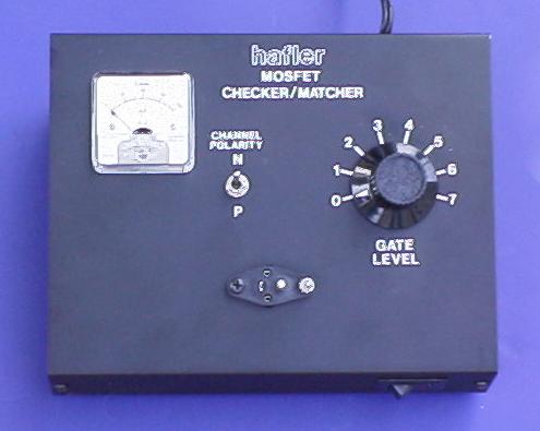
Anyways, I would build a Nelson Pass jig. I assume in that Hafler box there was a built in multimeter and thats what the needle meter is for. The MOSFET's Gate-Source Voltage is +/- 14V, so I gather that my power supply cannot be higher that + or -40V. And I can't draw more than 7A, or I will destroy the MOSFETs.
2SK134 pdf, 2SK134 description, 2SK134 datasheets, 2SK134 view ::: ALLDATASHEET :::
I assume the little rotary selector (Gate Level) 0-7 is just connected to a bunch of resistors (R in the schematic above) to allow different amounts of current to flow though.
Is this right?
Also, here is Mr. Pass's article http://passdiy.com/pdf/matching.pdf
I really want to build a Hafler MOSFET checker for my own use instead of finding someone to test them for me. Hafler never released schematics for their checker unit, probably as it was used internally only. I have some questionable MOSFETs from some old Hafler amp, and besides testing them, want to match and grade them to finish the other channel in my XL-280 conversion into a Musical Concepts PA-4 amp.
http://www.diyaudio.com/forums/solid-state/31131-hafler-dh-200-220-mods-111.html#post3415258
He had a Hafler MOSFET Checker/Matcher device.
Anyways, I would build a Nelson Pass jig. I assume in that Hafler box there was a built in multimeter and thats what the needle meter is for. The MOSFET's Gate-Source Voltage is +/- 14V, so I gather that my power supply cannot be higher that + or -40V. And I can't draw more than 7A, or I will destroy the MOSFETs.
2SK134 pdf, 2SK134 description, 2SK134 datasheets, 2SK134 view ::: ALLDATASHEET :::
An externally hosted image should be here but it was not working when we last tested it.
I assume the little rotary selector (Gate Level) 0-7 is just connected to a bunch of resistors (R in the schematic above) to allow different amounts of current to flow though.
Is this right?
Also, here is Mr. Pass's article http://passdiy.com/pdf/matching.pdf
I really want to build a Hafler MOSFET checker for my own use instead of finding someone to test them for me. Hafler never released schematics for their checker unit, probably as it was used internally only. I have some questionable MOSFETs from some old Hafler amp, and besides testing them, want to match and grade them to finish the other channel in my XL-280 conversion into a Musical Concepts PA-4 amp.
Last edited:
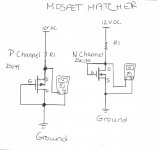
Okay. I drew a schematic to the best of my ability. I attached it. The max gate source voltage is ±14V so a 12V power supply will do. Hafler matched each MOSFET at 100mA, what value resistor is needed for R1? From what I concluded I need 120Ω resistor as R1 to allow 100mA of current to flow through the MOSFET?...
Provided my circuit is correct I would do just that, and note down the voltage reading and get others with the same (or very close) voltage reading. THat brings me to the next question. What does the knob GATE LEVEL do? Does that change the value of R1? I wonder what the meter on the Hafler checker even says.
Provided my circuit is correct I would do just that, and note down the voltage reading and get others with the same (or very close) voltage reading. THat brings me to the next question. What does the knob GATE LEVEL do? Does that change the value of R1? I wonder what the meter on the Hafler checker even says.
Attachments
Last edited:
Matching with Vdg set to zero volts does not replicate amplifier operational conditions.
But this 0Vdg matching is far better than random.
Vgs of a Lateral is quite low. Look at the datasheets for good guidance on what to expect.
If you want 100mA of Id and Vgs is ~600mV then a resistor of 10r in the drain feed will drop 1V and Vsupply should be set to about 1.6V, not 12V.
This very low supply voltage results from setting Vdg to zero volts.
R1 could be switchable to suit different Id.
Maybe 1r, 2r, 5r, 10r, 20r would suit your range of Id.
Maybe 1r, 2r, 5r, 10r, 20r would suit your range of Id.
This entire thing seems to be so complicated. Different answers from different people. (also asked on AudioKarma) Can someone just draw the correct schematic with the correct values so I can test these MOSFETs? They are checked with 100mA of current through them. Is a heatsink needed in this case?
Also what do you folks thing the GATE LEVEL control on the Hafler MOSFET checker does? adjust the value of what we think is R1? Also what is the needle display for? My guess is that it is a DC voltmeter inside too.
Also what do you folks thing the GATE LEVEL control on the Hafler MOSFET checker does? adjust the value of what we think is R1? Also what is the needle display for? My guess is that it is a DC voltmeter inside too.
Last edited:
For 12 VDC.
R1 = 100 Ohm
would be a good value. Gives like 80 mA.
R1, 100 Ohm, would be a power resistor at least 2 Watt value.
The MOSFET under test can have a small heatsink. Probably.
R1 = 100 Ohm
would be a good value. Gives like 80 mA.
R1, 100 Ohm, would be a power resistor at least 2 Watt value.
The MOSFET under test can have a small heatsink. Probably.
Last edited:
But does anyone know or can guess what the needle and the GATE LEVEL control do? I'm guessing the needle is just the DC voltmeter, and the GATE LEVEL is a pot or a switch to select different resistors...😕
Why not design and build your own MOSFET tester? Then you can have it perform exactly those functions that you think are most important. For example, you might feel very strongly that "matched" FETs ought to have near-identical values of
- VTH
- gm at bias_point_1
- dIDS/dVDS ("output conductance") at bias_point_2
Why not design and build your own MOSFET tester? Then you can have it perform exactly those functions that you think are most important. For example, you might feel very strongly that "matched" FETs ought to have near-identical values of
Then design and build a circuit which lets you measure these quantities, quickly and conveniently and accurately. Who cares what some guy once put into a Hafler testing box, 25 years ago, when you can design and build your own optimized test box today?
- VTH
- gm at bias_point_1
- dIDS/dVDS ("output conductance") at bias_point_2
Because Hafler's test box was designed for their application, and mine would be for the same application.
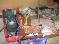
I had a similar tread open while building the F5
I was matching VGS
One thing to consider is the temperature of the beast as soon as you run a current trough the mosfets VGS change with the temperature
so I made little test bed for steady 50C this to keep similar parameters as amplifier and reduce ambient influence
I was matching VGS
One thing to consider is the temperature of the beast as soon as you run a current trough the mosfets VGS change with the temperature
so I made little test bed for steady 50C this to keep similar parameters as amplifier and reduce ambient influence
Attachments
- Home
- Amplifiers
- Solid State
- Matching MOSFETs