Transformer impedance and local feedback.

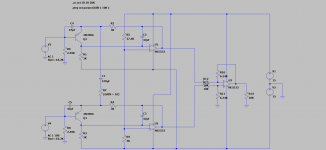
I am thinking primarily in terms of SET but I suspect the issues involved are kind of universal. Here is my thinking; please critique.

Load impedance on the output tube affects power output and distortion. Starting at some "optimum" load if one reduces the load impedance the maximum power delivery goes up but so does distortion. The question is simple but I suspect the answer is less so. Let us say that 5K is the normal load which gives good all around performance. If you were to reduce the load to say 4K but add local feedback such as plate to cathode could you get a best of both worlds situation with higher max output power but similar or even improved distortion due to the FB? Of course I am assuming sufficient gain.

On the one hand the plate curves are not changed (I don't think) but the local FB reduces effective driving impedance and reduces distortion in a brute force way.

So is this a reasonable way to make use of lower than optimal load trannies? Dumb idea?

Dynaco ST-150 PC-43 question

Hi, Gang,

I'm making a new PC-43 with Eagle and do not have an original board. I'm incorporating all of the Boak-Jung mods from AA plus a few other tweaks of my own.
I know that Q6 has to thermally track Q10 & Q11 by mounting on the same heat sink and have laid out the board for that.
Looking at the copy of the board fab in the assembly manual, Q8 and Q9 are adjacent.
Can anyone kindly provide a picture of a populated PC-43 or tell me if Q8 & Q9 should also share their own heatsink?
Also, does anyone know where to get the little TO-92 clamps Dynaco uses to attach Q6 (and other TO-92s) to a heatsink? These are used on the ST-150 and all versions of the ST-4xx, but I'm not finding anything like that in Digi-Key or Mouser.

Thank you!
Cheers,
Frank

Mackie SWA1801Z amplifier board

Hi everyone ! I have a problem with the amplifier of a Mackie SWA1801Z subwoofer! it does not have damaged transistors or mosfets, but the delivered power does not correspond to the characteristics and the output signal has a crossover distortion at low volume. Another strange thing is that if I try to send more input signal the output signal does not increase and the output value does not exceed about 30v RMS. Is it possible to have the wiring diagram? Thank you and good job to everybody

Attachments

  • 20220628_150605.jpg
    20220628_150605.jpg
    548 KB · Views: 267
  • 20220628_150559.jpg
    20220628_150559.jpg
    556.6 KB · Views: 264
  • 20220628_150541.jpg
    20220628_150541.jpg
    506.4 KB · Views: 207
  • 20220628_150822.jpg
    20220628_150822.jpg
    599.6 KB · Views: 207

  • Locked
The battle of the DACs, comparison of sound quality between some DACs

Hi guys!
given the cancellation of the last open threat without any explanation. I state that the material I was lucky enough to be able to bring is available on this site.
I also state that I have no interest in speaking well or someone might say promoting the following products.
I bought a lot of material from ian, ryanj, bisesik and of course also from andrea mori so I talk about my experience as most people do in every forum.
We did a listening day to compare various dacs, all with the same source,
usb-i2s andrea's fifo notebook.
we were 5 people one hifi enthusiast for years and a great listener of live music, two have come from over 40 years of DIY in hifi, I from 5, the last one also for a long time in DIY.
we all agreed on what I wrote below.

7) SABER the first of the participants - ES9038PRO sigma-delta driven in true sync. The worst we heard that day, flattened, lack of dynamics, grainy and veiled midrange, tight and shallow soundstage, lack of focus

6) Twisted Pear Buffalo III SE - ES9038PRO sigma-delta still true sync. slightly better, same defects, but far from what we were looking for

5) TWSDAC-AD5791 - AD5791 20-bit R2R dual mono sign magnitude. slightly better, but perhaps less dynamic than the saber.

4) DDDAC1794 - Doede Duma PCM1794A 24 bit sigma-delta dual mono sync NOS. Here the situation improves, nice musical to listen to but a too relaxed sound, lack of energy, the midrange remains a bit flattened, quite detailed but still narrow and shallow soundstage

3) TWSDAC-1862 - AD1862 20 bit multibit R2R dual mono sign magnitude NOS. At this point the qualitative leap starts to be significant, regular midrange, very detailed but never harsh high frequencies, deep and articulate solid bass, sufficient dynamics, bigger and more focused soundstage

2) TWSDAC-1541 - TDA1541A 16 bit mutibit R2R dual mono sign magnitude NOS. Further improvement compared to the previous one, one of the best medium ranges ever listened to, less wide but clear and soft high frequency, even more solid and extended bass, excellent dynamics, wider and deeper soundstage. the sonic planes begin to come into focus. definitely the best dac chip ever made.

1) TWSDAC-LT-DAC Lite. 24 bit multibit R2R NOS with digital calibration. The best we've heard, impressive dynamics, but never broken down, even smoother midrange, open, detailed, crisp and never harsh high frequency, deeper and more articulate bass, much wider and deeper soundstage than all DACs, no confusion between the floors and between the tools. here the result is truly incredible on every aspect. seeing is believing.


WhatsApp Image 2022-06-01 at 13.54.11.jpeg


WhatsApp Image 2022-06-01 at 13.54.10 (4).jpeg
WhatsApp Image 2022-06-01 at 13.54.10 (3).jpeg


WhatsApp Image 2022-06-01 at 13.54.09.jpeg
WhatsApp Image 2022-06-01 at 13.54.09 (2).jpeg


WhatsApp Image 2022-06-01 at 13.54.09 (1).jpeg
WhatsApp Image 2022-06-01 at 13.54.07.jpeg

Looking for source for 4.4mm plugs and jacks

I've been looking high and low for quality gold planted 4.4mm jacks and plugs, but i'm not having a lot of luck. I can find a few cheap as hell jacks with those damn pin terminals, but I'd like ones that have proper soldering tabs. I'm looking for both cable to cable male and female gold plated 4.4mm connectors as well as right angle through hole / panel mount female gold plated connectors. preferably a place where I can order 1 to start out with, and if I like it by the hundreds afterwards.

I've tried the usual digikey, mouser, arrow, octopart etc. looks like the only sellers are aliexpress / alibaba and resellers

Thanks.

Alpine PDX M6 - 43VDC Output

There is limited information on repairing only the Alpine PDX (gen2), so I figured make a thread only for the PDX. Long story short - I found out after getting my JL 13TW5V2 repaired by JL for $230 😡 that the amp was the reason why the sub failed (melted cone + snapped voice coil), not my occasional listening preference. If you hear a loud turn-on thump while using a PDX, turn your head-unit off immediately to preserve your speakers. The protection circuitry is only to prevent an over-current, over-voltage, and ultimately thermal runaway condition for safety and liability purposes - its not trying to protect your speakers.

My PDX M6 outputs a constant 43 VDC voltage, regardless of whether any signal input is provided to the RCA input. After reading through various other experiences with this amp, and the MRV (or MVR) which uses the same class D switching, I am planning or have already:

1. Done - Exercised the theory of having a loose subsonic switch 'in the middle' of the three state options. With only power/remote connected, the speaker output was still constantly 43VDC, while switching between 30 Hz to 15 Hz to off did nothing. It was set at 15 Hz.

2. Done - bench power the unit at 14.4VDC, then probe the audio driver ICs to check whether they are working properly. I've read through issues which other's have experienced on both amps, and it sounds like the original PWM audio driver ICs can go bad rather easily. I have the M6 Service Manual with all the test point voltages - so I may as well test. Update..PWM driver ICs were ok, all 8 FETs were ok, spot checked some other components on the bottom board and they were ok. I didn’t check anything on the top because that ribbon cable is so short...I’m sure a tech would have a longer ribbon cable for proper testing. Seems like the problem worked itself out once I fed it 14.4VDC.

3. To-Do - Replacing both 98-1036TRPbF PWM audio driver ICs with an IRS20965S, then test to see whether the 43VDC goes away. If it doesn't go away, I may end up just sending it in for repair.

4. Optional - Replacing all 4 Power Supply FETs and all 4 output FETs. If the amp resumes operation after replacing the IC's, I may still go ahead and replace the FETs to refresh the amplifier - hopefully clock in a higher true power rating. The FETS all look good (they aren't brown or cracked), don't have any shorting, but 'fail' a handful of FET tests - caveat is that they are still in-circuit.

If anyone else has any other thoughts or has experienced the same failure, please chime in to provide some assistance. Thank you in advance!

Micromega Tempo 1 schematics, draft

Hello, please see attached part of Micromega Tempo 1 power amplifier schematics.

I tried to reverse engineer it and draw circuit diagram of the power end.
It is DRAFT so it includes mistakes, wrong part numbers etc but maybe this encourage someone to finish it.

I made it using Kicad so if someone wants a Kicad file then let me know. The attachment is pdf.


Enjoy

Attachments

New OB project with Faital Pro 8" coax and 18"

I sold my house and won't probably have a dedicated hifi/TV room ever again. So I will build new speakers for the living room.

My latest effort was a two way OB (planar+15") plus IB subwoofer. See picture.

Planar combo was very clean sounding, but it was also a bit too polite at low volume.

I recently bought a pair of Faitalpro 8hx150 at a great price.
https://faitalpro.com/en/products/Coaxial_Loudspeakers/product_details/index.php?id=351030100
I plan a 3 way with OB coax on top supported by an H frame 18fh500 at bottom. DSP xo at 1700 and 160hz.

I already made a quick test with naked coax supported by a 15" and it was very promising. There was no ringing or harshness when the Tweeter was EQed and gain adjusted. Compared to planar combo, this setup has more dynamics, realism and body. It was a short test period, but to my surprise, I did not miss the dipole upper mid and treble. We will see how it goes once the build is complete.

Comments welcome on design and driver selection.
IMG_20220330_182155.jpg

Volt BM228.8 Tweeter pairing (Two-Way)

Hey everybody,

Over the last few weeks i've finaly been taking my first steps into making my own loudspeakers.
First project has been a crazy setup for a 16 channel sound installation, where i got to design all loudspeakers.
Notably where these coaxial SB Acoustics 5" and 6" variants, but maybe more on this another time.

Long story short: Great experience to built something, now let's find out what we can achieve with a little more budget.
The plan is to build a set of small studio monitors using the Volt BM228.8 woofers and i'm looking for a good pair of tweeters to go with them.
All will be powered and filtered by a Hypex FA123 (using two channels bridged to drive the woofer).

On the short list so far are:
Scan-Speak D2905-990000 (Have been used in this configuration before, as i found out)
blieSMa T34A-4

Both tweeter should be able to go low enough to cross them around 1.6; matching the Volt.
So here's the main question: Does anybody know any other tweeters to look at?
Any general advice about my plans are also quite welcome as well!

Thanks in advance!

_DSF3983Small.jpg

SOS help! Amp is in protection mode

Good morning everyone,
I purchased this power acoustik razor RZR1-2500D amp from Walmart, I had a friend of mine set up the amp . I come to find out that the amp isn't giving no sound and the amp is on protection mode. Can someone please guide me the right way.

Attachments

  • PXL_20220625_141333915.jpg
    PXL_20220625_141333915.jpg
    525 KB · Views: 1,343
  • PXL_20220625_141431366.jpg
    PXL_20220625_141431366.jpg
    354.8 KB · Views: 504
  • PXL_20220625_141506676.jpg
    PXL_20220625_141506676.jpg
    375.4 KB · Views: 889

Wiring for dodecahedron loudspeakers

Hi all! Hope you are well and keeping safe in these strange times!

I'm currently building a dodecahedron loudspeaker for acoustic measurement purposes, but I'm looking for some advice on wiring the 12 drivers.

I think that professional manufacturers use a combination of series and parallel wiring to prevent the resitance from getting too high / low, but I'm looking for any advice from this forum as to how many parallels and how many series connections 🙂

The speakers I'm using are 4 ohm, (12 of them, obviously 🙂 ) and the amplifier I'm planning to use has an output of 2x400w @ 4 ohm.

My main concern is safety, and not setting the house on fire!

Any advice is greatly appreciated and will be repaid with beers if you are ever near Wigan UK 😀

Altec 605B crossover

Hi all,

I have been using this crossover on my 605Bs for a while, favouring it over the Markwart version. My question however is : what's the correct/nicest way to pad the horn 1-2db? 2 resistors in an LPad configuration after the all-pass filter? a series resistor before or after? anything else? I have calculated several lpad values and tried them, but usually feel it brings some messiness in the crossover region.

Attachments

  • xsim_605B_sch.png
    xsim_605B_sch.png
    3.7 KB · Views: 124

Hi-Fi amplifier using STK4042Xi

Hello,

I have made this amplifier (Fig. 1) out of pure curiosity – I wanted to test a pair of brand new STK4042Xi ICs sold by Reichelt GmbH from Germany. My tests indicate that rumors about fake STK ICs are wrong, at least if you purchase them from reputable supplier. I don’t know who is producer and where the ICs were produced, but I can conclude, that the measurement data are consistent with the original SANYO technical documentation.

The product came as a positive surprise: both subjective impressions and measurement results are quite fine.

From the results below (Fig. 2) one can conclude, that based of these ICs it is possible to build a fine 80W Hi-Fi amplifier.

Measurements indicate that THD is consistently much lower than 0,1% and also that there is a very low noise floor. Measurement results of harmonic distortion present in a 1KHz and 10 KHz signal at 30W output are presented in Fig. 3 and 4, respectively.

To make this amplifier I have used:

2X STK4042Xi (Note that the suffix Xi indicates High Fidelity product)​
1X PCB from Aliexpress (Tianle HiFi STK 4040-4050)​
1X 400VA/230V toroidal transformer with double 30V secondaries​
1X Heat sink (Fischer Electronics SK56 100, 0.4K/W)​
List of components is in the attached .7z file​

For testing I have used:

Oscilloscope Rigol DS1074Z-S Plus​
Arta software​
Sound card: Xonar U7 Mk II​

Figures

Fig 1. A photo of the amplifier on the test bench
STK4042Xi-Amplifier-01-Resized.png

Fif. 2. Measurement results THD (+N) values at different power outputs, at 1KHz

Measurements-01.JPG

Fig. 3. Measurement of the harmonic distortion present in a 1KHz signal at 30W output
STK-01-1KHz-Resized.png


Fig. 4. Measurement of the harmonic distortion present in a 10 KHz signal at 30W output
10 KHz-Resized.png

Attachments

  • Locked
Another ebay steal !

Bought a 4 channel McGregor 150 Watt amplifier off ebay.
Opened the box and it looks very nice.
So powered it up and connected a source,
It is very distorted and volume goes up and down on its own where ever or which ever volume pot is set.
All the volume controls crackle when turned.

I did quick look online for circuit diagram but couldnt find one.
So I am returning it.

Why people "try" to sell their junk I dont know as ebay just force a return on them meaning they pay outbound and inbound postage.
It wasnt sold as spares or repair so it should have worked ok.
Its sellers like this that give ebay a bad name.
  • Like
Reactions: dazcwl and rayma

2SK1530Y/2SJ201Y and 2SK2013Y/2SJ313Y New production inquiry POLL

Hi
I have asked Profusion manufacturer if they would be interested in producing new lots of the famous obsolete audio application Toshiba mosfet complementary pairs (2SK1530Y/ 2SJ201Y or 2SK2013Y/2SJ313Y) and they responded that they would consider it if there was enough demand. This manufacturer is already producing the famous audio lateral mosfet that are copy of the 2SK1058/2SJ162 and other copies of famous BJT also for audio applications.

So this thread is a poll to get the number of Diyaudio members that would be interested in buying some of the mosfet. Just add you name in the list.

LIST:
Member name / Qty of pairs (2013/313) / Qty of pairs(1530/201) / Note
Fab / 10 / 10 / comitted to
…..

If we get enough interest I will report the results to Profusion. Ensure that you are very interested in your indicated quantity. You can add a note for your interest level such as “Possibly/Very/ Comitted to”
Have in mind that they could be pricey such as the Exicon mosfet (example: >= 6 Euro or so per transistor).
I can also ask for “S” grade (selected VGS group matching for same type channel.

For the possible use I can see great potential in replacing IRF610/IRF9610 (or FQP3X) by 2SK2013/2SJ 313 and IRFP240/9240 in existing amplifiers while adjusting some resistors values for VGSoff difference of course. For example, in an F5 amplifier it made quite a sound improvement in my experience.

As you already know, there are also already good existing designs using these mosfet.
Additionally, I have recently designed and built new prototype amplifiers using my remaining stock of 2SK1530/2SJ201 based on USSA3/5 or FSSA variations. More to come on that.

Fab

FS: Monacor WG-300 waveguides (x4)

SALE PENDING!

I used these with Vifa XT-25 tweeters and I can't imagine using the Vifas without them due to improved dispersion and sensitivity. These are a great match for just about any 1"dome tweeter. I had to import these from Europe which wasn't cheap and last I looked you still can't buy these within the U.S. No longer available from Europe Audio either.

Asking $50 shipped per pair or $90 shipped for all four within the US. PM me for international shipping quotes. First to pay gets them, no "dibs" or delays. PM me for Paypal info.

Trying to understand this gain control circuit

Hi all, have been lurking here a long time and have learned a ton from you all. Hoping you can help me answer some questions I can't seem to find answers to. Please let me know if this is the wrong forum to post this in.

I've been looking at the Mackie ProFX mixer schematic to understand the gain structure. From the user perspective, the line inputs feature a gain control that goes from -20dB to +40dB, with another +10dB available on the fader. Looking at the schematic, I can see that there is a voltage divider at the input that cuts -20dB, followed by the gain circuit that appears (per my simulations) to add a variable amount of gain between +6dB and +56dB. There is another gain stage near the fader that adds another +6dB, the fader itself is just a voltage divider. There's probably some other attenuation in there, so I see how it more or less all adds up to what is advertised on the front panel. I have questions about how this gain circuit actually works though:

1) This circuit (page 2 of linked schematic) is located before the circuit that unbalances the signal, so it is effectively duplicated for both + and - inputs, and therefore requires two transistors (IMBT4403) and two op-amps (NJM4580). I've simulated half and the gain is exactly the same, so I'm wondering why they did it this way. Is it so CMRR could be used to reject some of the noise introduced by the gain stage? Would it be much noisier single-ended?

2) I vaguely grasp that the transistor in the feedback loop is being used as a current amplifier to increase loop current and thus the gain of the op amp, but I would like to better understand the physics/math and be able to calculate gain and other circuit characteristics.

3) How does the gain pot actually vary the gain of the circuit? It is in series with a 470uF cap, bridging the emitters of both transistors. I presume that it allows some current to leak so the gain is lower, but again, I would love some clarification on how it actually accomplishes that. Also, that cap seems to cause some low-end roll-off (-3dB at 30Hz, see attached frequency response); I would have expected the 3dB point at a lower lower-frequency. Maybe they boost bass later in the circuit?

4) Would this perform similarly with different op amps/transistors? Is there anything special about the choice of components for this purpose? I simulated using 2N3906 and NE5532 since I didn't have models for these components. Would they perform well in this circuit?

Thank you, I look forward to your thoughts!
Steve

Attachments

  • Mackie ProFX Gain Control Frequency Response.png
    Mackie ProFX Gain Control Frequency Response.png
    8.3 KB · Views: 259
  • Mackie ProFX Gain Control Schematic.png
    Mackie ProFX Gain Control Schematic.png
    20.4 KB · Views: 278

Jumping capacitors (parallel)

so putting capacitors in parallel.

couple questions.

1) does say putting one cap in a xo with a value of 18uf make a sonic difference rather than having one 16uf cap jumped by another cap of 2uf ( =18uf) ? Is better to have just one cap with the 18uf value or the two jumped equaling that value?

2) does the cap you put on to jump the other make the sonic difference? For example if you had a cheap electrolytic and jumped it with a poly cap, would the sonic characteristics be that of the poly cap?


thanks in advance !

2.7mH vs 3.0mH air core inductor

Hello,
I'm a complete noob to diy. I've been an audiophile for more than two decades. Recently I made a friend who had built a set of the CSS Criton 1tdx speakers. They sounded great. I decided to build a set, but use better parts in the crossover. I am matching the values, just using upgraded resistors such as duelund and copper foil inductors. Which leads me to my dilemma. I can't source the required 3.0mH inductor (outside of a jantzen wire one). I can find a 3.3 mH and a 2.7mH mundorf. I can't seem to find any explanation of the effects of using a slightly higher or slightly lower value inductor. Can anyone explain it in simple terms for me? Can I substitute a sightly different value without destroying the sound? Thanks everyone.

Modernized Altec Lansing A-324A Clone

Hi all,

I've been a member of this forum for a long time but just lurked, now it's time for me to muster up the courage to actually post something here.

I've always had a thing for Altec Lansing (their brand was quite popular in India in the late 2000s and early 2010s) and the first audio device I bought with my own money was an Altec Lansing 2.1 active speaker system when I was in middle school. Fast forward, I got into amplifier design (mostly chipamps and then discrete BJTs, all Class AB) and very recently built my first tube amp (the AE-1 from following the tutorials on the Analog Ethos website) and now I'm hungry for something a bit more advanced.

I found the schematic for the Altec Lansing A-324A and I'm given to understanding that the amplifier stage was common to quite a few Altec products of that era and was actually a decent-enough HiFi performer. So I thought, why not just build that circuit and I'll have an Altec Lansing tube amp, which would be quite a big deal!

Of course, things aren't that easy, and I have questions.
  1. The Altec TL-217-B output transformer is a 6600-ohm primary transformer. A modern equivalent I'd like to use is the Edcor CXPP60-MS-6.6K. However that OPT only has a single 8-ohm primary, and the A-324A seems to run its feedback circuit off of a 16-ohm output tap. I suspect that this will need a change to the feedback resistor R23. Could someone suggest what I could replace it with, or better yet explain the math so I can calculate it myself?
  2. The input pentode (6J7) is really hard to source in quantity - all I can do is buy NOS and hope they don't break - but I suspect a roughly drop-in replacement would be the 6SJ7 or the Chinese 6J8P. Do you have any other ideas of what else I could use? If it's something current production, all the better.
  3. I'd actually like to analyse this amp and see what the operating point of the input pentode is, what kind of gain it's configured for and if I can replace it with some other kind of current production triode (of course, then it wouldn't exactly be an Altec amp and will also sound different, but I'm also happy with an "inspired by Altec, designed by me" amp). Maybe use a 6SN7 or 6SL7 and use one half as the input gain stage, and the other half as the phase-splitter. But this math is way over my head (I'm a comp-sci major doing database storage engineering, I took an undergrad-level elementary analog electronics class and fell in love with electronics that I could hear, but this means some stuff that's obvious to the experts here is fairly alien to me). If someone has the patience to explain this math to me and walk me through figuring out the operating point of that 6J7, I'd be very grateful.
The objective here is to build the design (and maybe design a pretty case for it), and I don't care too much about using "audiophile grade" stuff. I don't have much of a budget, so I'll just order parts off Digi-Key that seem within a reasonable level of tolerance, and use Electro-Harmonix or JJ or Chinese current production tubes. If I really love how it ends up sounding, I can always rebuild the circuit with better components and/or tubes. The A-324A seems to also use a 400V B+ supply, so I'll also just re-use the power supply from the AE-1.

Thanks,
Boud

[1] Circuit Schematic: https://web.archive.org/web/20110924120419/http://www.theused.com/manuals/altec/altec_a324a.pdf
[2] Altec Transformers reference: http://altec.bayoucables.com/AltecTransformers.pdf

WTB: Twisted Pear Audio Mercury I/V Stage

Looking for Twisted Pear Audio Mercury I/V Stage.

Currently, I have 8 channel DAC project with 5 IVY-III I/V Stage boards (4 for 8ch and 1 for 2ch out). As I'm going to upgrade from ES9018S to ES9038Pro, at least one I/V stage should be upgraded as well. The original price for Mercury board is a bit expensive for me 🙁 So I hope I'll find someone with spare Mercury board on hands 🙂

Cat 5e speaker cables

Here are some speaker wires I built.

I used Cat 5e wire for the midrange and tweeters.
IMG_8718.jpg


IMG_8721.jpg


Separate the white from non white and strip.
IMG_8722.jpg


Rinse and repeat
IMG_8724.jpg
IMG_8726.jpg


Terminate
IMG_8738.jpg
IMG_8759.jpg


Install

IMG_8812.jpg


Then I started on the main cables keeping the cat5 sheath intact but again separate all the colors.
IMG_8765.jpg


Strip and strip and strip and twist
IMG_8767.jpg


Terminate
IMG_8799.jpg


Cover and complete.
IMG_8804.jpg


Rinse and repeat.
IMG_8808%20-%20Version%202.jpg


You'll notice I used simple 12ga wire for the largest drivers in my speakers because it took way to long and my fingers were sore for days. 😱 :snail:

How do I use Icepower 300ASC Balanced with speaker containing active powered woofer?

Hi.
I just got a pair of Icepower 300ASC-based mono amps (Emotiva PA-1) which are fully balanced (input to output).

My speakers are a three way with 6" woofer and tweeter passively crossed over, but the 8" lower woofer has an active amp and crossover.

Previously, I'd connect both the upper passive driver binding posts along with the woofer amps high-level input to my amp terminals (the woofer amps also have a single rca input).

However, the new amps' manual says DO NOT connect the balanced outputs to a device with a common ground.

Anyone familiar with a solution for this(that doesn't require replacing or redesign of the current speaker/woofer amp.

Thanks in advance for any assistance.

Isolating the TT "Grounding Wire" from a floating Pre-Amp Chassis

Hi All,

I have a turntable (TT) that has its metal chassis grounded to protective earth (PE), as would be expected. Also grounded to this chassis (via a tiny ~30AWG wire) is the tone arm, internal cartridge wiring shield and the “grounding wire” – a small diameter wire (~20AWG) that is intended to be connected to the chassis of the pre-amp. The pre-amp consists of two metal enclosures – one is a PSU and is connected to PE, the other is the amp itself and is galvanically isolated from the mains via the trx and it’s appropriately rated insulation (the design and build has been checked by competent and qualified persons). If I connect the TT to this pre-amp without the “grounding wire” I get a 50Hz hum (as I expect). If I connect the “grounding wire” to the chassis of the pre-amp the hum goes away (again, as expected). The problem is that by connecting the “grounding wire” (referenced to PE in the TT) to the pre-amp the galvanic isolation of the pre-amp is lost, as the pre-amp chassis is connected to the 0v rail of the secondary of the trx (see attached sketch). I am trying to figure out the best way to solve this issue. The options that I see as possibilities are:
  • Possibly the ~30AWG wire connecting the tone arm et al to the TT PE is unlikely there for safety as such a small wire couldn’t carry any significant fault current so perhaps this wire could be removed and the tone arm floated (it has no other connection to the chassis apart from this tiny wire);
  • Possibly an isolation trx could be used between the Pre Amp and the TT’s grounding wire;
  • Possibly the TT could itself be isolated from the mains with an isolation trx (this seems expensive);
  • This I’m not entirely sure of, but could a “ground lift” device be used? As previously explained on this forum and others C and R in parallel along with a diode bridge is used to float a signal GND from PE. If this could be used, would the diode bridge be needed as the wires involved are effectively signal GND’s , although one is referenced to PE in the TT?
Can anyone help me determine the best way to solve my issue?

I have attached a sketch of the wiring.

Many thanks in advance.

Attachments

  • TT and Pre-Amp sketch.JPG
    TT and Pre-Amp sketch.JPG
    278 KB · Views: 149

MTX MXA6001

Not as familiar with MTX amps as the others.
This amp uses 75339P PS FETS. I've never seen them before.
Is it normal for these power supply mosfets to heat up so quickly?
I know it is not in the heatsink, but I have never had power supply mosfets get this hot in only a few seconds. From my experience the outputs are the ones you must pay special attention to.
The gate resistors are 61R9 and read good.
R117 in the pic reads good but is very discolored. Would it be wise to replace it with a higher wattage?

Attachments

  • 20220321_105953.jpg
    20220321_105953.jpg
    660.1 KB · Views: 231

Small speaker Dayton RS125 and vifa tweeter.

** SOLD **

needs to go by end of June

Pick up from Mt Pleasant DC 20010

Lovely little speaker to suit a small room or use as near field monitor (been using them next to my computer)
Not made by me - purchased Sept 2021 from fellow DIYA member @Dkalsi - who did a lovely job when he made them
I have really enjoyed using them while based temporarily in DC - they have great detail and in ok level of bass. Good down low or at volume.
But we are moving on and try as I might I can't find the space in my suitcase otherwise I would take them with me.

Dayton RS125
Vifa tweeter
Walnut veneer finish with translam baltic birch baffle
9" x 6" x 8.5"
23cm x 15.5cm x 21.5cm

CD jewel case for size comparison

Asking $130 plus cost of post

Attachments

  • IMG_6303.JPG
    IMG_6303.JPG
    367.6 KB · Views: 244
  • IMG_6304.JPG
    IMG_6304.JPG
    452.5 KB · Views: 228
  • IMG_6305.JPG
    IMG_6305.JPG
    375.2 KB · Views: 218

Replacing Knobs with sliders ?.

So Im sitting at the work bench with a few pre-amps and tone control boards.
Some have come with Knobs some have come without knobs.

Im trying to draw up what my control panel will look like. Mains power s/w. AMP selector switch, Speaker selection switch.
Im going for a steam punk look. And had this idea. Can I replace the knobs with Sliders.
So slider for volume. Smaller sliders for Low / Mid /High balance control.

I did some reading And searching.But all the sliders I found have 3 pins only.
Like for the pots you get a double gang i.e.6 pin. Do you get double gang sliders. ?
My pots are all 100K. So replacing them with 100K sliders work ?.
I could always have two sliders for each control but Na that would take up too much space.
Any help with the right part name or what its called would be helpful.
Just want a confirmation that the idea will work before I blow money buying these sliders.

I found this.
https://robu.in/product/sliding-adj...ZrUJfP4t65YAIHM9StX64o7d5HMf5_OhoC_cEQAvD_BwE

and

https://www.ebay.com/itm/265128598401?_trkparms=amclksrc=ITM&aid=1110006&algo=HOMESPLICE.SIM&ao=1&asc=240037&meid=88a453539075480cbc72f5725c0e09a6&pid=101195&rk=3&rkt=12&sd=281782160222&itm=265128598401&pmt=1&noa=0&pg=2047675&algv=SimplAMLv9PairwiseWebMskuAspectsV202110NoVariantSeedWithRevOpt90NoRelevanceKnnRecallV1&brand=Bourns&_trksid=p2047675.c101195.m1851&amdata=cksum:26512859840188a453539075480cbc72f5725c0e09a6|enc:AQAHAAABMAoNKsJM3HOHkM0OuV9XKcsoXSMLk3wBBxTIYdgqgcSsJbD%2BWQW2%2Fi9%2FH9y8TZ%2F9TU3Es3oTKRolT9u5mF91RnSGjcRDdDpXI3GNi9QMheFP623sd2luaveQWWobQW5%2FEZdkQxxL1xR3GssHJroZdzCBpXxJOsPw0QMSolT00G4BYqZScYxhbUSYAdCh3xUsLbzLu%2BJpfd39LQ5SvGL7JgM0JpliD5d0n2A1S0WfooJSnDUz%2Feq0ZRhydrRfnwJN5Z8mbLPYEq%2F4JF5dKZg0lhjtcXKIYijiRabJLjXX%2B0cMCxQSotf6eq3An84%2BjcBJGVY49tCsA28P9MjqDaqC%2Fpw2NrXL780OTIWWCqbSRpD52CtjaIy2E5gdRKGqIn9QCsCmS8HAqOVWfVA%2FDz5R0qM%3D|ampid😛L_CLK|clp:2047675

Quad 303 Clone - Only 12V on each board despite 67V after regulator board

Hi,

I have built up new clone boards for an old non working 303 I bought recently and can only achieve 12.7 volts maximum on each board despite being able to set the regulator voltage to 67 volts as it should be.
I have checked I haven't done anything silly and cannot see anything obvious, but have duplicated the problem as it is the same on both boards!
Any suggestions?

Thanks,
Colin

Charlies line preamp with 6N8S

Hi all can you help me with this project, I'm just a tube noob here.
Charlies line preamp with 6N8S instead of 6sn7s.
Is it a good tube within operating specs?
Looks like max voltage is 330.
Any help from the community would be greatly appreciated
Thanks in advance...... Robert

Attachments

  • SNvvb.jpg
    SNvvb.jpg
    36.1 KB · Views: 203
  • 6N8S.pdf
    6N8S.pdf
    100.4 KB · Views: 90

VBE multipliers.

Since, BJTs input junctions conduct an electronic current exponentially, it needs some voltage for this little current to reach levels that are encountered in amplifiers. This is usually about 0.6V to 0.7V. However, this little voltage causes crossover problems if it is not addressed. The latter function, is usually done by VBE multipliers. This thread is intended for users to post those VBE multiplier topologies and even actual circuits which they found to perform best.

I am still hesitant about changing the VBE multiplier circuitry of my amplifier. It seems, it is impossible to implement a VBE multiplier or equivalent with a sharp step characteristic and with full temperature compensation. There are various variables involved often requiring approximations to the level of regulation needed.

4 Pi Speaker build - need help with “doping” the JBL 2226’s to make them less ugly

I bought a used pair of the JBLs for this kit and, while they sound good, they look terrible. Kind of a rat-like color that does not impress SWMBO. I'm looking for suggestions to make them look darker and less rat-like. I've heard one guy suggests using MinWax wood hardener for this purpose, and to make them last longer. I've also seen people who have used hair spray, diluted varnish, contact cement, all sorts of stuff.

Any ideas appreciated.

Thanks,

Alan

Attachments

  • A0CA930A-BD65-45AC-99D1-5442B5D30FDC.jpeg
    A0CA930A-BD65-45AC-99D1-5442B5D30FDC.jpeg
    156.2 KB · Views: 347

Pair of ACA amps

For sale: pair of ACA amps built to specs with upgraded caps. Kits purchased from this site, built to specs with standard Mean Well power supplies.

$750 plus shipping from 46835.

Attachments

  • IMG_2434.JPEG
    IMG_2434.JPEG
    341.6 KB · Views: 116
  • IMG_2433.JPEG
    IMG_2433.JPEG
    402.8 KB · Views: 111
  • IMG_2432.JPEG
    IMG_2432.JPEG
    350.4 KB · Views: 117
  • IMG_2431.JPEG
    IMG_2431.JPEG
    339.6 KB · Views: 80
  • IMG_2430.JPEG
    IMG_2430.JPEG
    477.5 KB · Views: 113
  • IMG_2429.JPEG
    IMG_2429.JPEG
    450.6 KB · Views: 110
  • IMG_2428.JPEG
    IMG_2428.JPEG
    444.2 KB · Views: 116
  • IMG_2427.JPEG
    IMG_2427.JPEG
    406 KB · Views: 111
  • IMG_2425.JPEG
    IMG_2425.JPEG
    460.6 KB · Views: 110
  • IMG_2426.JPEG
    IMG_2426.JPEG
    451.8 KB · Views: 103
  • IMG_2424.JPEG
    IMG_2424.JPEG
    378.6 KB · Views: 121

Several steel chassis and covers for sale in South UK

1) Chassis for a project (valve amp or radio). This is a folded and welded bare steel chassis, professionally made. Dimensions are (+/- a couple of millimetres): 386 x 260 x 93 mm with a 21 mm lip on the bottom 1.4 mm thick steel. Heavy. Not drilled or punched. Minor rust marks in places. With base plate. £15 collected.
2) Chassis for a project (valve amp or radio). This is a folded and welded steel chassis, professionally made. Dimensions are (+/- a couple of millimetres): 410 x 138 x 62 mm, I forgot to measure the lip, ask if this is important, 1.5mm steel. Heavy. Not drilled or punched. Minor rust marks in places. £10 collected.
3) Two half chassis. Folded steel “J” shaped to form up to a square tube (no end panels) 340 x 380 x x57 mm. One has a 75 mm diameter hole in the middle 70 mm from the long face and some cuouts in the "front" face (see photo 6). 3.25 mm thick steel! Heavy. Minor rust marks in places. £10 Collected.
4) Two steel covers. These are “U” shaped with stiffeners/flange and louvres. I forgot to measure these but about 4” x 4” x 12” (I’ll measure if any interest). Heavy. Some small holes near edges. One is black crackle finish and the other black matt, £10 collected the pair.
Any and all can be collected from Battle near Hastings in 1066 country most days or early evening. They are quite heavy so will absorb a lot of vibration.
I can deliver in the Eastbourne/ Hastings area for petrol costs. E&OE.

Attachments

  • DSCF6200.JPG
    DSCF6200.JPG
    81.8 KB · Views: 119
  • DSCF6201.JPG
    DSCF6201.JPG
    81.2 KB · Views: 115
  • DSCF6202.JPG
    DSCF6202.JPG
    83.5 KB · Views: 100
  • DSCF6203.JPG
    DSCF6203.JPG
    82.8 KB · Views: 104
  • DSCF6197.JPG
    DSCF6197.JPG
    78.8 KB · Views: 107
  • DSCF6199.JPG
    DSCF6199.JPG
    84.9 KB · Views: 109
  • DSCF6204.JPG
    DSCF6204.JPG
    95.5 KB · Views: 113
  • DSCF6205.JPG
    DSCF6205.JPG
    112.6 KB · Views: 114
  • Like
Reactions: Grarea

21PW1400/Fe low frequency transducer PW Series

Re Beyma 21" Woofer 21PW1400/Fe PW Series.

As a matter in interest only, how far up the range could this woofer be taken?

Usually such a transducer would not be taken much above 2-300Hz but it seems quite smooth further up.

Quotes range is up to 1.8Khz, frequency response is quite smooth up to that range. However no impulse response plots are available so there is no way of knowing how it would perform, distortion looks quite reasonable however.

http://www.loudspeakerdatabase.com/Beyma/21PW1400Fe

https://www.beyma.com/speakers/Fichas_Tecnicas/21PW1400FE.PDF

Hi folks...

I just registered, after browsing some of the older content here, and just wanted to say this really looks like a great site. I look forward to meeting and getting to know some of you. I'm an EE by profession, but the bulk of my training and experience has been in digitally-related arenas. I've gotten quite interested lately in things like audio, RF, etc. I'm planning to tinker with some amateur radio work, and I also have an old circa 1938 Zenith floor standing radio that I'm going to attempt to restore. Just getting geared up now to start shaking down its power supply circuitry.

Hope everyone is safe and well! -- Kip

Supravox 215 EXC - 8in Field Coil full range drivers (pair) - $1,300

Well, I have to get real with myself and realize that life and work are just too demanding to allow me the time right now to take on my OB dream project. I have collected just about everything needed but have never found the time to cut the baffles and bring this project to conclusion. And so, with a heavy heart, I am letting the dream go for now. Maybe someday I'll pick it up again.

This project was inspired by the following article in Six Moons. 6moons audio reviews: A 4-year journey into open baffles with widebanders. I am listing each component individually so please check my other listings for other items for sale.

Here are a few links for these amazing full range drivers:

215 EXC Full range drive unit 20W / 90 at 99dB / 4 Ohms - Supravox

The Supravox Field-Coil Chris Bryant gets back to basics with a simple full-range drive unit driven from an electromagnet. Review By Chris Bryan

High Efficiency Speaker Asylum: REVIEW: Supravox 215-2000EXC field-coil driver Speakers by tinos

Pics available

my new Marantz CD-73 and RC430 RMC12

I purchased a nice working Marantz CD73 but won't be able to pick it up until this weekend.

I also purchased the RC430/RMC12 remote unit separately from another seller and just received it this morning. It powers on and everything seems to work, my question is how to hook it to the CD73?

The remote unit has what looks like plain RCA cables but coloured orange... does anyone know what cables will work? Included is a stock pic found on google

Attachments

  • RC430_CD73.jpg
    RC430_CD73.jpg
    154.2 KB · Views: 497

Testing ESL power supply boards

Hey guys

I currently have a set of power supplies and crossovers from a Martin Logan Quest that I'm wanting to find a way to properly test prior to hooking them up to anything. The amplifier hooked up to the speakers either blew up in a very had way or was exposed to some kind of power surge. The power supplies look ok other than one has a blown resistor near the bottom.

If the ESL power supply board and main transformer are still ok I should be able to save this speaker. Any help is appreciated as this whole electronics repair hobby is pretty new to me, no shops will touch this stuff so I have to do it myself.

Power supply 1 has a blown resistor inline with the speaker signal wires that turn the power supply on when you play sound.
PXL_20220609_110242777.jpg

PXL_20220609_110247100.jpg


#2 looks fine, no physical damage, but must be tested
PXL_20220609_110236296.jpg
  • Like
Reactions: NE WAY

QUAD ESL 989 For Sale

My Quad ESL989 speakers have been in my ownership for around 3 years. I originally bought them with a view to “improve” them, but on arrival, they appeared to be faultless so nothing has been done other than to change the outer “sock” which was black to a new blue sock, obtained from One Thing Audio. Other than that, they are as they were shipped by Quad. They were serviced at Quad in August 2014 and have consecutive serial numbers 901255 and 901256.
Any prospective owners should be aware that these are large speakers, but at last, they give the electrostatic design the bass which has been missing for so long from Quad ESL products. I should add that I have owned around 6 ESL 57s of various vintages and I much prefer these speakers in terms of detail, depth and power.
The sound, as you might expect, is superbly detailed, voices extremely natural, and transients just amazing. The speakers are connected to Hypex NC400 Class D amplifiers, which are totally silent and well known for their performance. Music sources are generally FLAC files from a music server.
The speakers are unmarked, in original condition, all panels are working without any transient pops of clicks and the speakers are available with the original packaging from Quad
Listening is highly recommended, as is collection from our location, which is just south of Cambridge.

Attachments

  • P1040474.JPG
    P1040474.JPG
    177.6 KB · Views: 366
  • P1040475.JPG
    P1040475.JPG
    254 KB · Views: 254
  • P1040476.JPG
    P1040476.JPG
    482.1 KB · Views: 251
  • P1040477.JPG
    P1040477.JPG
    366.4 KB · Views: 302

Can a electronic load this?

Hi I usually use an electronic load with nearly no functionality or to be honest, I think it have some features but the manual and the unit is almost impossible to get to do anything. 30 min of trying for 60 sec of constant current test!


I am thinking if it is possible to buy a new electronic load where I can program "sweeping" resistance, i.e. to test an amplifier from 8 to 2 Ohm or to test how a power supply react to change in load.


Is that something an electronic load normally can do?
What would you recommend, a Siglent?

Datasheet and reality

I have been looking at the MJE15028/30/32 and MJE15029/31/33 transistors from ON Semi. The datasheets clearly show a hfe of 150 at 25C stable up to 1A, then falling as we approach the 8A limit. This for both NPN and PNP ; actually the charts are shown side by side.

From that I would determine that I am guaranteed hfe=150 if I keep it below 1A and over 25C.

So I have bought around 3 dozen pairs of those transistors, and I measured them at home. Many I measured at 1A, others at a very small Ic (but the differences were minimal).

I discovered that the PNPs have outrageously high hfes, most were around 360 with a good bunch at 380 as well. A batch of 20 PNPs from RS turned out to be at a uniform constant of 250, which is the smallest I have measured.

The NPNs were all over the place, but consistently between 80 and 150, with only a couple at 150, most were around 100.

I spoke to Farnell about this and they have assured me these have come straight from ON Semi, no brokers in between.

I have posted a similar question before, cannot remember where, and was told not to design anything that depends on the hfe being either matched or of a specific value.

Well, I am finding all this nonsense. If the datasheet says 150, so it should be, otherwise it makes a mockery of the datasheet. At worst it should be higher than stated so that they transistors can still be driven almost as expected, but not below (by over 50% of the stated value for the NPNs and by 100%-150% over for the PNPs). The PNPs are in a world of their own, so here I am trying to match my push-pull stage with one side having hfe of 100 and the other side having a hfe of 300.

So why bother buying these transistors if they behave as badly as 50 year old BD911s ?

In my opinion something is fishy here. Why is the datasheet showing them as complementary, made for each other, like Adam and Eve, with charts shown side by side, with the SAME datasheet covering both NPN and PNP - when the truth is so far beyond all this?

any degradation with 3.5mm to RCA?

I changed my preamp the new old classe lacks any 3.5 MD input. A converter is my one option for now.

Whats your take on source wire converters generally?

Is it possible to replicate the very same sound by the time it reaches the amp with a different coaxial source connector?

My new situation calls for something like this https://www.analogueseduction.net/mini-jack-interconnects/carilin.html

I prefer connecting to laptop this way, instead of the USB to DAC. Because I refuse to switch this DAC after it took what seemed like forever to find one I want to stay with lol.

Hey there!

After almost 2 decades of being out of the loop when it comes to home audio and home theater I recently was gifted a pair of speakers and an amp. They do have do their issues though, and being a fan of DIY, I figured that this was a great reason to get back into audio.

After lots of casual lurking around different forums and whatnot around the internet, this forum stood out to me and is one of my favorites. So, here I am!

I'll be asking a fair amount of questions in the future since the speakers I've got have issues. I'll post my questions later on in the relevant sub-forums. I look forward of things to come, thanks!

need pre amp and schematics for connecting amp

hi everyone i have some electronic components home, i have an amplifier board alone i mean no alimentation no pre amp nothing would like to make and use it.
it has kta1268. ktc3206. 2sc4137. 2sd2493
as ic's. its already assembled....
just need an preamplifier board, a digital to analog converter,electrical converter to use with the amp and speakers board and protection.

Attachments

  • IMG_20220626_043119.jpg
    IMG_20220626_043119.jpg
    282.3 KB · Views: 184

JBL M2 in wall clone

Looking for some advice on how bad an idea it would be to build some JBL M2 clones. It's alot of money to me to do this, so I need someone who knows what they are doing to give their opinion.

Image 1 is my living room right now.

Proposal is in wall speaker version of a JBL M2. (Image 2- yellow wall added)

The 'false wall' would house a pair of M2 waveguides for my 4inch compression drivers (2452SL) and the M2 bass driver.
I don't have the D2430k M2 compression drivers, but am told the drivers I have work well and are if not better, at least comparable.

Why go through this vs buying/building some more regular speakers? SPL playback regularly reaches 112db+ at 1m for my living room, and big boxes get a no from the wife. I can also hide a large sub in the wall.

1) Is the response going to be completely screwed up by the side wall reflections and being in wall?

2) Erin (Erin's audio corner) notes that the M2 bass driver has some diffraction issues with the accordian surround. Is there a better 15 inch alternative? I have some AE TD10m drivers, but assume this would not match the pattern of the 15inch I would be replacing, and also assume distortion would be higher at 112db+ sub or not.

Current living room:
Screenshot 2022-06-12 215226.png


Proposed design:
Screenshot 2022-06-12 213503.png
  • Like
Reactions: Naturlyd and Flaesh

FS: 4 x VIFA TG9 mini array

$100 with free shipping

4 x tg9 (copper cap) wired in series/parallel.

3/4" bb ply sides, top/bottom, back
1/4" front

1 : 1.618 ratios

6" deep x 9" wide x 15" tall

Acousta stuff inside

Rolls fast at 200hz.
If used for music, you will need a woofer, not a subwoofer.

Amazing intelligibility for late night listening to movies.
Think picking up on pink floyd division bell lyrics without focusing on them, it's that good.

I recommend baffle step circuit of 1.7mH + 2.5 ohms
For an extra $15, i can send you the jantzen inductor i am using.
https://www.parts-express.com/Jantz...5k235TNc1onuHXSEu7MUDBAV4FhBuYGxoCOdgQAvD_BwE

Sitting 10' away, i'd say the sweet spot is about 1' vertically, horizontaly as wide as any other 3 inch driver.

I had builder fill in where front baffle wasn't flush to box.
Was a squeek more low mids that wasn't there before.

Shark not included.


Money order please.

Thanks for looking !!!!!!!

Attachments

  • 20220418_020306.jpg
    20220418_020306.jpg
    320.4 KB · Views: 205
  • 20210908_134411.jpg
    20210908_134411.jpg
    453 KB · Views: 219
  • 20210908_134300.jpg
    20210908_134300.jpg
    437 KB · Views: 192
  • 20220418_020144.jpg
    20220418_020144.jpg
    381.4 KB · Views: 189
  • 20220418_020212.jpg
    20220418_020212.jpg
    333.3 KB · Views: 203

Help deciphering N34 tube data

I'm trying to figure out the data sheet for the n34. The basic stuff is there but there are a bunch of blank columns. I don't know if the blank ones simply don't apply or what is going on. It says the heater is actually 13v, I assume that 12.6 is close enough to not affect performance, right?

Also, I can't find where I downloaded this file. Nor does it have any distinguishing titles on it, anyone have any idea what the whole publication was and/or know where to download this again? Thanks.

Attachments

Help needed to identify this section of the circuit

Hi, I need some assistance to identify what this part of the circuit does. It appears to be 2 x 10K ohm resistor and 1 x diode. This is right after power filter capacitors. I have also tried to draw a simple dircuit dragram (sorry I am using MS word to draw).

I tried googling and it appears to be capacitor bleeding circuit but I don't really understand how it works.

Why does 1 set connects from -ve to +ve while the other set is +ve to +ve?

I am also wondering if it makes any difference connection the fuse before or after the capacitors.

transformer -> rectifier -> capacitors -> fuse -> transistors (fuse after capacitors)

transformer -> rectifier -> fuse -> capacitors -> transistors (fuse before capacitors)

It would be great if folks could help me on this.

Thanks!!!

1656293732782.png


1656294649016.png


1656293816852.png

Tweeter protection grille for B&W Matrix 805

Hi to all. I have a pair of original 805s but got them with only one protective grille for the tweeter. I was looking for replacements options, but it is not available anymore from bwparts; I think I caught it once on eBay but with an insane price.
Nevertheless, I wass wondering if someone knows maybe if a grille from another model could fit? (e.g. I found some images of the grilles for XT4 and they appear as they could be adequate, but could not find enough further details to properly confirm).

AD1862, 1865, DAC PCB.

I have found four unused AD1862 and a two AD1865 plus another two used AD1865. The AD1862 were bought in a group buy from Rochester electronics a few years ago.

Also found a tube of eight AD844AN pdip.

Also a pcb for a pair of AD1862 from diyinhk.com

https://www.diyinhk.com/shop/audio-...fo-reclock.html#/dac-dac_pcb_without_dac_chip

Please make me an offer for all or any if interested.

I am gifting the two used AD1865 to the buyer of the other two as I cannot test them and also including free of charge, my own dual TDA1541 dac pcb with I2S input (from an Ian Canada PCM to I2s interface.) and a dual AD1865 pcb (has a short marked with a dot).

Attachments

  • mydac.jpg
    mydac.jpg
    205.9 KB · Views: 232
  • used1865.jpg
    used1865.jpg
    162.3 KB · Views: 246
  • dacpcbtop.jpg
    dacpcbtop.jpg
    418.8 KB · Views: 264
  • allitems.jpg
    allitems.jpg
    216.1 KB · Views: 268
  • 1865a.jpg
    1865a.jpg
    86 KB · Views: 249
  • 1862pcb.jpg
    1862pcb.jpg
    319.6 KB · Views: 244
  • ad1862.jpg
    ad1862.jpg
    109.5 KB · Views: 248
  • Like
Reactions: yogiDIYbear
Projects by fanatics, for fanatics
Get answers and advice for everyone wanting to learn the art of audio.
Join the Community
507,723
Members
7,885,801
Messages

Filter

Forum Statistics

Threads
406,120
Messages
7,885,801
Members
507,723
Latest member
semajbab