B&K microphone power supply - help needed

I've got myself into a possible problem.
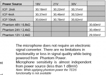
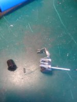
I bought a B&K 4000 series mic. It was cheap - on ebay $250 (1300 dollar mic). It was a measurement mic used in a lab, complete with the base/preamp. Flat as hell, basically omni. I figured it might sound good for recording (was I crazy?), but I need a good measurement mic anyway, so I bought it. A B&K is going to be quality gear - so I took the risk. This is a prepolarized mic, so it does not need polarization voltage, only a little current to run the "preamp" - in the base of the mic (the 2671).

It has BNC a connection. 2 wires. Turns out the correct power supply costs like 500 bucks. yikes. I forgot it might not be a standard phantom power (48V).

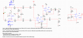
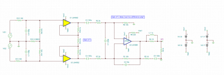
So, the question is, how can I build my own power supply? The issue is not the supply voltage/current since I can look that up - (I assume I can get a wal-wart that will be close enough from an electronics supplier), but the conversion to xlr (the 3 pin connector which is the interface to the mixing colsole). Which of the two wires is hot (signal or ground), and how do I keep the current out of my board? If I apply current to the ground, it will short. If I apply it to the hot, I will hurt my mic pre or the mic, maybe. But the power supply has to use one of those wires. B&K can not answer these questions in their support (they tell me to buy the power supply). I don't know exactly how phantom power works - so this will give you an idea of my state of ignorance.

Solid State Relay for an amplifier mains power switch

I expect this has been discussed but the search is not working for me.


Regarding if a Solid State Relay for an amplifier mains power switch degrades the musical sound quality from the loud speakers during music play?


Everything else I've used does in the various, but generally very revealing Hi-Fi systems I've tested with.


Have you personally tried an SSR and what was the effect on the sound from your loudspeakers. Did it have a negative effect, if so what? How did it compare to relays, mechanical switches, mercury switches, huge contactors, anything else you tried?

Please let me know what methods have been found to be the most transparent way to switch the amplifiers mains power on / off.


For switching on/off power to domestic amplifiers, e.g., 100W to 300W per channel stereo and mono amplifiers. 500 to 1000VA Transformer, 40,000 to 100,000uF. UK 240 Volts 50 Hz AC.

Whilst there are a lot of people who's very limited experience has them believe that cables, plugs, switches, have no effect, others know the fact that they all do modify the music, and sometimes in a big way.

I've been making mains cables and attempting to get a transparent mains supply for decades.

The best by very far that the test system sounded was to solder a 25mm² 'super spur' direct to the amplifier transformer with no plugs, switches, fuses, tracks, anything, other than an appropriate fuse at the meter board after the distribution block in it's single carrier, that also acted as the switch by simply pulling it out of it's carrier. Neutral with no switch, just going into the distribution block. The installation being compliant with the UK 16th edition regulations.

Obviously that's not a practical way to operate a domestic hi-fi, so I made and inserted various switches at the amplifier between the spur and the transformer, all had a very disappointing and damaging effects on the tonal balance and realism of the sound quality.

Also that means soft starting and DC, etc., protection that cuts the mains supply is not possible without severe compromise of the sound quality.

I made a 16 pole main relay, contacts bridged with 2mm² copper rod at the contacts, hopeless.

Spent £70 for a high current mercury switch from industrial cookers, just as bad as the multi pole relay.

I somehow fitted and soldered the 25mm² conductors into an IEC plug with the socket pins soldered to the transformer lead in wires, terrible. IEC plugs for me have been bad for the sound, even the ridiculously expensive ones.

So, to my request for help and the point of this post....

I've not yet tried sold state relays.

The high repetitive current ones are expensive and I don't want to waste a further load of money if the tests have already been done and the results were not any good.

Thanks. 🙂


Note: My personal preference is that this thread is maintained as an informative useful resource for anyone looking for information.

To keep it tight, clean and meaningful the chaff has to go or it dilutes the meaningful content about the subject of my enquiry.

Wharfedale Super 10/RS/DD as studio monitors?

I've got a pair of Wharfedale Super 10/RS/DD. To my ears they sound somewhat similar to my NS10's, having rather forward midrange but I've never tried mixing on them. If anyone has experience with these, would they be good enough as a studio monitor? I was thinking making smaller encolsures, the originals are huge, nowhere to put them on the desk or even in my small room.

NXP i.mx RT600 as a USB DSP

Hello everyone,

I'm looking to build a USB DSP to accompany my Class-D AMP I build a few months ago. It uses an Infineon ma12070p chip and is basically the reference design for a fully digital two-channel amp with I2S input. link
The idea is to have 2 active desktop/bookshelf speakers with full streaming capabilities (USB, Analog IN, Digital IN and maybe some network streaming options) with DSP crossover and room correction, feeding a 2-channel AMP over I2S.
While looking for options I started with an implementation based on the FreeDSP project (aurora) using an ADAU chip for the DSP and an XMOS 208/216 for the USB I2S stream. Due to the availability of the parts, the ADAU implementation is not so attractive anymore, and the XMOS chip is generally very expensive and I don't like the provided IDE.

I came across the NXP I.MX RT MCU chip family and was wondering if this would be the candidate. The RT600 has an M33 and a HIFI4 cadence core. The documentation seems good and chips are available. Instead of an expensive evaluation kit, the teensy 4.1 can be used, it features a very similar chip from the same family. Depending on DSP processor power and IO functionality, the RT1024 could be used, if I choose to hand solder.
The chips can be programmed in C-like language and have support for Zephyr, so there should be a community out there to help with that.

Has anyone tried these chips for a DSP/DAC project or is interested in doing so? Every help is appreciated.

Best Fabian

JBL PB12 subwoofer, Class D amp, dead.

One of my friend just gave me a blown PB12, there is a class D module amp, where everything seems to be in.
The circuit seems to be repaired and looks like there was a lot of rework from factory. I know this unit never been opened by a redneck or so, my friend dont even have screwdrivers.

So, is there some schematics that i could get, or some inputs. I do think that the source of the problem is the module, wich is a small heat sink and some urethane molded behind it. When i turn it on, the woofer pops in with huge hummmmmm. Dead for sure.

Sources for this part?

It seems that there is a lot of bad coments on this subwoofer.
?

Thanks

Pat Allen

FIRST DIY SUB - 15" in progress, pics. Check my design before I seal it up?

More pics, calcs, and WinISD files here: https://www.dropbox.com/sh/o2xls2ha7ibzuoo/AAB3Lj5jyOo4v97BEQAqN11Ea?dl=0 theres a subboxpro link in the txt

This is my first TV, speakers, and subwoofer ever. Please review and lmk what you think so far.

I bought a Dayton 15", a Crown XLS 602 to drive it, and a minidsp to control the signal with EQ and bandpass filters.

this is the speaker: http://www.loudspeakerdatabase.com/Dayton/DCS385-4

I did a lot of research but am still a rookie. The background is: I was reading about getting some decent speakers on the internet, got the jbl 530s on sale and then read I should get a sub to go with it, and people said I could build my own for cheaper and they'd be better. I watched youtube videos and read around and like fun project to do and went down a rabbit hole and now I have this. I even built the TV console custom to fit this dimension sub underneath. I learned about winisd and added some EQ for a flat profile while not breaking xmax. Oh also the port velocity, its under 20. But that's all I really checked, I don't know what the rest mean really so if anyone experienced here wants to take a look and help it would be appreciated.

All the port panels and braces are still unattached, so I'm wondering if y'all have any comments before I finish the port side of the box and seal it up. I could still change the tuning frequency/port length a bit or add more bracing. I am gonna round out the port corner and seams with liquid nails. This is going underneath the shown TV console I built so the box is strictly limited in the given dimensions/volume.

My goal for the sub is when I'm playing videogames or watching movies, when an explosion or something goes off it will go "boom" and sound good. Just kidding, the TV is only used by my wife to watch The Real Housewives....

Attachments

  • console.jpg
    console.jpg
    361.8 KB · Views: 128
  • sub4.jpg
    sub4.jpg
    544.1 KB · Views: 133
  • sub2.jpg
    sub2.jpg
    529.1 KB · Views: 119

Constant current microphone that is P48 compatible - how does it work?

Isemcon have a line of ICP (4 mA constant current) microphones that are P48, in fact also P24 and P12 compatible. They claim that they can be used with no degradation of performance with 12 to 48 V phantom power. The adapter is a straight connection of pin 2, while pin 3 is simply grounded.

This is the data sheet. The information is the most detailed for the 7001 model, but they are all electronically the same:
https://www.isemcon.net/ashop/datasheets/iSEMcon-IEPE-CCPmic.pdf

This is an independent review of the ICP mic and the real P48 version that comes with an XLR connector rather than BNC. The ICP version was tested with aid passive adapter:
https://www.isemcon.com/datasheets/iSEMcon EMM-13D082.pdf

It shows that ICP version used with P48 has 10 to 18 dB higher harmonics in the range of 100 - 120 dB SPL. Beyond that, there is little difference, with the P48 version being only about 1 dB better.

I get that the built-in 6.8k resistor with P48 can be seen as a constant current source, and if the drive electronics in the mic have sufficiently low output impedance (< 10 R in this case), there will be little degradation of the signal.

I also get that the sensitivity is slightly higher if the CCS is set to a higher current because this means the ampflification of the internal source follower is closer to unity. And I get that sensitivity decreases towards P24 and P12 because there is a lower current and because the feed resistor is lower than with P48.

But why would the mic care about the compliance range of the CCS? This is specified at 18 - 30 V. I get that you don't want too high an upper limit because it may blow the mic amp on startup. But why would the sensitiity depend on the limit? The output will stabilize at 7 V +/- 2 V. At that point the amp won't know whether the CCS compliant is to 18 V or to 30 V, and 18 V should be sufficient to insure +/- 6 V signal swing.

The marketing gibberish is of little help: The built-in prepolarized microphone cartridge controls an AC/DC-Zener Diode circuitry with an output impedance as low as 10 Ohms

Attachments

  • Isemcon_ICP.PNG
    Isemcon_ICP.PNG
    52.3 KB · Views: 138

Building the Ariel

Hello everyone!

In 1999 I discovered the Ariel speakers so that in 2000 I bought the speakers to make them. Then I realized that I had neither the skills nor the tools to build them. So I stored my speakers for a better day.

In 2020, I lost my job. And since we were in the middle of a pandemic (and here in France we were confined) I thought that my chances of finding a job quickly were handicapped by a number of important factors (the first being my age). So instead of wasting my time looking for a job I couldn't find, I decided to go back to school. I am now a proud cabinetmaker.

A few days ago my 14 year old son decided that there was no other way to listen to music than on vinyl. So he spent some of his savings on a turntable which is pretty good quality if I am to believe what I have read about it.

So I have a son who needs quality speakers, speakers in perfect condition still in their packaging, the skills and tools (including access to a 5-axis). It's time to build the Ariels!

I'm going to build the 6c version. I reproduced the plans in FreeCAD to make them a bit more to my liking (and especially to the thickness of the French plywood). I have two questions:

1- in the plans it says "1/2 cedar". Is it really solid wood? And which cedar is it? Red cedar?

2- After finishing the plans, it was obvious that my revelator could not fit in the space provided. I then realized that I did not have D2905/950000 but D2905/990000. What is the impact on the speakers ? And in particular on the filter ?

Thanks

What is a kenotron?

So I'm picking out a 6V rectifier tube for a pre Amp and see that 6X5GT fits the bill as I have many of them in stock from old tube caddies. And its a 6S base so 6AX5 will fit it too and I have many of those too. Then I see the Russian tube 6C5S is a substitute for 6X5GT. But the Russians call it a Kenotron, USA calls 6X5 a rectifier. Whats up with that? Is a Kenotron in any smallest way different than a rectifier?

https://frank.pocnet.net/sheets/127/6/6X5.pdf

https://frank.pocnet.net/sheets/113/6/6C5S.pdf

Recommandation for PP about 30-40W with 4K OPT w/o UL.

Hi,

I bought a few days ago an old Push Pull tube amp from a console and I intend to build something fun with it.

The single PT uses SS diodes and provides a B+ of about 450-475Vdc

The OPT are rated 40W, 4K ohm with 4, 8 and 16 ohm output. These OPT do NOT have UL tap. The OPT used to drive 7027A tubes.

I don’t like the sound of pure penthode without global feedback so I guess I’m looking at a triode strapped scenario of something similar. I don’t mind using tubes that were not designed for audio, I have had good success with sweep tube and the like, 807, etc. I’m also open for suggestion with using Russian tubes either as output tubes and/or driver. I do enjoy the 6P3S-e in one of my SE amp.

I’m aware that the usual tubes for 4k push pull is EL34 but would there another tube I could use based on your experience ? Most of my tubes stuff are SE power amp except for a push pull class A EL84 which provides 10W/ch, I really enjoy it but would like power on my 4 ohm speakers.

What I’d like to build now is a more powerful amp, something with guts 😉

Thanks in advance for some recommandations.

Eric

Jl Audio 300/4 repair

Hey, I have a JL 300/4 with a broken channel, that broke last week. It looks like what's in red is shorted , and have a couple of resistors to replace too that have gone with it.

But I can't find what's in red and can't find anything. I can find what the tops transistor are but this one I have no idea.

Does anyone have any clue?

Thanks in advance

Attachments

  • jl.jpg
    jl.jpg
    341.1 KB · Views: 203

Particular sounds

Login to view embedded media good morning gentlemen in this official video of the song "watch out of this" by major lazer, I heard some particular sounds the first goes from minute 1:07 and in particular from minute 1:11 to 1:15 and the other sound to minute 1:58. you may notice that hearing them seems to make you paralyze or bring you into a hypnotic trance, what are these particular sounds called?

Cracking open tweeter

Had a set of old tweeters that I decided to refresh the Ferro fluid because it very gummy. When dabbing out the old fluid the center of the magnet shifted so it was no longer a symmetrical gap for the voice coil to drop. I ended up prying up the center when trying to get it centered again.

Ended up prying the whole thing up. Any ideas on the best steps forward?

Attachments

  • 20220801_181002.jpg
    20220801_181002.jpg
    170.8 KB · Views: 140

Equalising gain in an active set up

Imagine you have a 3 way speaker and you want to Tri-amp it using an analogue active crossover. The amps are not all the same and let’s say that 2 of them have 20dB gain but the 3rd one has 26dB gain. What I am trying to get my head around is this; if I use a dedicated volume control to effectively reduce the gain of just that amp from 26dB amp to 20dB and permanently leave the volume control at that level of attenuation, have I effectively reduced the gain to 20dB for all input levels, or will the attenuation in dB be different as I vary the input level ie turn the volume of the source up or down ?

Not easy to describe, hopefully you will get my drift . . .

For Sale Patrick Bateman specials (aka Unitized Image Control waveguides)

As seen in this thread. These are the best ones John (Patrick Bateman) printed. I bought them off him and as seen in the thread, sanded smooth, painted & top-coated them. They are roughly 8.5”W x 6.5”H x 3.25”D.

The Gento midrange drivers are included (eight in total); all that’s still required is tweeters for the pair: SB19ST

These could be used towards a great, one-of-a-kind active monitor setup using DSP.

I paid $199 for the pair and that is what I would like to sell them for. Buyer covers shipping. CONUS only.

Attachments

  • FB1CE5E4-F728-4D81-8DE7-1E5792A87F46.jpeg
    FB1CE5E4-F728-4D81-8DE7-1E5792A87F46.jpeg
    412.7 KB · Views: 350
  • 45A1F81D-18BA-4C2F-8324-42A3EDC34A3D.jpeg
    45A1F81D-18BA-4C2F-8324-42A3EDC34A3D.jpeg
    475.6 KB · Views: 361
  • ACEA8C75-7989-475D-8BC2-A2C6C86244DF.jpeg
    ACEA8C75-7989-475D-8BC2-A2C6C86244DF.jpeg
    305.2 KB · Views: 351

Schematics needed for knight KG 895 integrated stereo solid state amp, i can’t find a schematics for this amp , can some help!

Hi , i cannot find a schematics for my KNIGHT MODEL KG 895 Solid state stereo integrated amp , I tried hifi engine.com they don’t have it , I can’t find anything on this amp online , can some help it , it will be much appreciated ! Thanks. Sikander you can email a copy at salihingoro@gmail.com

Canada Was Offline Today

Today Roger's Telecom of Canada was down again with an 18 hour outage. In addition to Internet and mobile phones, a huge number of services were affected such as ATMs, transportation, payment terminals, etc. So 10 million wireless subscribers and 2 million retail subscribers were dead in the water, annoyed, and disappointed. I am surprised it took so long to find root cause of the problem and resolve it.

This episode shows how fragile these eggs-in-one-basket do-everything-for-you systems are in the modern world.

I have Internet and TV from Roger's but wireless phone from Bell. So when the Internet died, I could verify on my phone ... yup Rogers is broke again.

Differential circuit from high level or low level input with switch selector

Hi! I started designing the circuit below in order to acquire car audio signals to my processor over ADC channels.

I want to scale down the audio source from high level or low level signals using a slide switch.
The idea is that both low level or high level signals can be plugged into the same "RCA" connector. Then, I would use the slide switch to select from "LOW LEVEL INPUT" or "HIGH LEVEL INPUT". I could not find any schematics like this.

Case 1 - High level input expected to max 10Vrms at RCA connector. This is the CH+ and CH- from car audio radio (wires that would go to speakers).
Desired: Differential outputs INN and INP need to be scaled down from max 10Vrms input to 5Vpp output differential.

Case 2 - Low level RCA audio source expected to max 4Vrms at RCA connector. This is the signal and GND of low level RCA cable.
Desired: Differential outputs INN and INP need to be scaled down from max 4Vrms input to 5Vpp output differential.

Note: Using single supply in all op-amps adding some offset at non-inverting input.

I assembled the circuit but it isn't good at all. Circuit has noise and its bandwidth is limited from 50Hz to 17kHz only. (Expected 15Hz to 20kHz range).

Could I get some inputs and recommendation of changes to fix those issues? I see that there are some failures in the approach.

Any help is very appreciated.

Thanks.


1657997622783.png

Attachments

  • 1657996385018.png
    1657996385018.png
    31.4 KB · Views: 163

For Sale Viborg pure copper Chasis mount XLR jacks for sale (new, never used, gold and rhodium plated available)

I bought a bunch of the Rhodium plated Viborg pure copper chassis mount XLR jacks for a project and then decided I didn’t want Rhodium and bought a bunch of the gold plated ones. And then I realized I couldn’t afford them all and just used Neutrik.

So my loss is your gain. A few of them were installed onto a chassis, but never soldered to wire, and never plugged into anything. So they are all like new in their original boxes.

These sell for $17-$18 each on Aliexpress

I’ll sell them for $10 each.

I have:

GOLD PLATED
male 16
female 6


RHODIUM PLATED
male 18
female 6

You can buy as many as you want. Shipping is free. Paypal Fees are extra.

Thank you!
Whitney

Attachments

  • 58AC8DC8-C84F-438B-808B-E8327BE71472.jpeg
    58AC8DC8-C84F-438B-808B-E8327BE71472.jpeg
    483.6 KB · Views: 104
  • B3ED94FD-FED7-496C-B49B-587665B98246.jpeg
    B3ED94FD-FED7-496C-B49B-587665B98246.jpeg
    475 KB · Views: 100
  • 05780E66-C4E2-400A-B515-2FE53BD7401C.jpeg
    05780E66-C4E2-400A-B515-2FE53BD7401C.jpeg
    499 KB · Views: 109
  • 86F60466-11D1-4FDF-93A0-EFCFB0431211.jpeg
    86F60466-11D1-4FDF-93A0-EFCFB0431211.jpeg
    503.1 KB · Views: 106

Domes on Horns vs Compression Drivers on Horns

For the past couple years I've been getting good results with domes on horns, so I thought I'd post some data that demonstrates why they work surprisingly well.

An externally hosted image should be here but it was not working when we last tested it.

In this corner, we have a Tymphany DFM2535R00-08 compression driver. It sells for $42. Here's some specs:

diaphragm diameter: 3.72cm / 1.46"
VC diameter: 3.55cm / 1.39"
"sensitivity" on spec sheet: 107.8dB
power handling: 30W

sb19st-c000-4.jpg

In the other corner, we have a SB Acoustics 3/4" dome tweeter. It sells for twenty bucks. Here's some specs:

diaphragm diameter: 2.2cm / 0.86"
VC diameter: 1.9cm / 0.75"
"sensitivity" on spec sheet: 88.5dB
power handling: 30W

PDo2Qp6.png

Here's a measurement comparing the Tymphany DFM-2535R00-08 on an 18Sound XT1086 vs a SB Acoustics SB19 on the same horn.

Same volume level, same horn, different drivers.
  • Like
Reactions: DblAA

Summer / Consolation Amplifier: 1995 Adcom GFA-5200

My two DIY amp projects, F5 and BA w BJT outputs have stalled for now, but look what fate (and craigslist) brought to me: a cute little Adcom GFA-5200 (an all-mosfet amp which NP designed, so that's why this post is here). I especially wanted the 5200, as it has a single output transistor per rail (whereas the 5300 has duals) and a single pcb with lots of empty space to work around. This will make a nice little summer amp to drive the top of my ESL hybrids, especially once I've completed my to-do list.
After a major vacuum, minor check-up, and revealing photo-shoot, I've punished it for over a week (making sure to test and re-test the thermal protect) playing the SL3's full-range. So far, no real guts in the bass and not so silky highs in stock form, but it shows promise.

Any chance of someone showing me a schematic?

Here's my immediate wish-to-do list:
Replace all the electrolytics
More PS caps (in the space thoughtfully reserved for them)
Thermistor to protect switch
New rectifier bridge made from 15A soft-recovery On-Semi MSR diodes and moved off-board
Re-route input leads (as they now take the scenic route close to the transformer!)

Long-term:
More heat sinking (and maybe redesign the cover to yield more space)
Bottom-mounted fan in silent housing
Transistor clamps + Kerafol insulators
More bias
Transformer-shielding and chassis-bracing steel plate

Attachments

  • Adcom GFA-5200 ADS1.JPG
    Adcom GFA-5200 ADS1.JPG
    375.3 KB · Views: 2,485

16C-B28 Sweep tube data?

I purchased a lot of compactron tubes from an eBay seller which included a number of Raytheon 16C-B28s and 1 Westinghouse 16CB28.

All appear to be NOS.

These are 12-pin tubes with anode top cap, and obviously designed for use as TV horizontal outputs.

I cannot find any tube data for these on any of the regular web sites -- anyone have a datasheet or further information on these?

Thanks,
Charles

Paraline physics

I have gone through the explanation of paraline lens, where a 2:1 ellipse is used to create a linesource of height equal to the ellipse's major axis.
But I also think that the sudden change of direction of sound waves will also will result in filtering of high frequencies. I suspect this might be the reason why Danley line sources don't go till 20 kHz, while point source synergies do.
1) What parameter of the paraline determines the low pass characteristics?
2) What parameters determine the lowest frequency the lens can be used for?
3) What is the directivity of paraline sound at various frequencies? (Danley's site shows extreme wide dispersion of 120 deg but is I am not sure if this occurs evenly across all frequencies)

@Patrick Bateman @SpeakerScott , if you could be so kind as to...

3way Discovery or...

Hi!

Wanna begin with new project of 3way speakers. Classical scheme - 10" + 5" + tweeter. Preffering sealed box. Budget about 350-400 euro on speakers set. Basic idea on discovery series 26W4534 + 15M4624 + some tweeter suitable. As alternative 3way on Seas Prestige. Say H1411 + MCA15RCY + some tweeter.

Need your advices and suggestions about best combinations in that price range.

Bipolar PSU Recommendations

I missed the timing window for paying for the Salas BIB group buy because I became ill so I need recommendations for an effective relatively compact PSU kit or at least PCBs with documentation capable of outputting +-30V at 600mA which I'll be using two of to power two SS Dynahi boards. What do you guys recommend, apart from the S22 which is too big?

EDIT: Here are the detailed specifications I want:

1. I'll be using a separate transformer so no need to worry about that. I just need the rectification and AC/DC converter section.
2. I want there to be either user-adjustable voltage with a pot or documentation which helps me chose the voltage through part selection without tooooo much hassle.
3. No positive/negative tracking required. Separately adjustable rails are fine. Don't really care how this part works.
4. Must be capable of an output of +-30V and be capable of at least 300mA of output current continuous per rail, preferably 500mA to allow for overhead.
5. Separate PCBs for the positive and negative sides are fine. The total volume of the combined positive/negative rails must however be smaller than the AMB S22 (6' by 3.5' by 1.5'.)
6. I don't care about what devices are used (BJTs, ICs, JFETs, MOSFETs etc are all fine) as long as it performs well.
7. Must perform at least as good as classic LM317/337-based PSUs in terms of output noise and ripple. Ideal performance roughly on par with the S22, Salas BIB, Goldenreference Low Voltage, etc.
8. Must be readily available in at least bare PCB form with adequate documentation.
9. I will however consider ones which have good, easy to follow documentation which require me to use e.g. protoboard to create the PSU. I'm an idiot, so treat me as such. 😛
10. Must cost at most the price of a Salas BIB to build.

So far, the ones I've found so far are the Salas BIB (which I unfortunately missed the group buy for), the S22 (it's huge though so ideally I want something smaller) and the goldenreference low voltage (GRLV) by Kevin Gilmore (very limited availability just like the Salas BIB unless I do up my own boards and/or start a group buy).

A Zen Split Load Amp

This design is taken from TubeCad.com. 6watts @ 8 ohms. Serious Iron for 6 watts. See Attached images for some enjoyment 😱 I designed this amp to replace my 2a3 Set.

Dwight

Attachments

  • 1EBF96C4-5435-4A9A-83BC-3D6223980F57.png
    1EBF96C4-5435-4A9A-83BC-3D6223980F57.png
    20.8 KB · Views: 1,182
  • 12F1B731-94C5-4FA6-8F71-C48F6431F3BE.jpg
    12F1B731-94C5-4FA6-8F71-C48F6431F3BE.jpg
    928.8 KB · Views: 1,139
  • 9E149E8F-E060-44A5-8DA0-6A4630F77879.jpg
    9E149E8F-E060-44A5-8DA0-6A4630F77879.jpg
    526.6 KB · Views: 969
  • 0C4D82CC-7215-40B7-A2E4-EFAFA728D5BA.jpg
    0C4D82CC-7215-40B7-A2E4-EFAFA728D5BA.jpg
    818 KB · Views: 1,083

(Paid) We are looking for someone who can help us with our woofer project

We are searching for a long time for someone who can help us to optimize our woofer model. Of course the work is paid.
Briefly about the actual job: We work in FEMM with an axis symmetric model. We have certain goals and mechanical properties that we want to achieve with the woofer and need someone to help us adjust the model to achieve them.

We would like to clarify the rest in a personal conversation.

Technics SU-V4 Schematic query

I am about to embark on repairing this amplifier and I have downloaded the schematic from hifiengine https://www.hifiengine.com/manual_library/technics/su-v4.shtml

Looking at the power transformer and rectifier area the centre tap of the transformer secondary is shown connected directly to the -48V rectified output rail. Surely this must be incorrect since it means diodes D404 and D406 are directly across each of the output windings. Normally I would expect the centre tap of the transformer secondary to be connected to the 0V (GND) rail at the mid point of the main filter capacitors C403 and C404.

Can anyone offer an expert opinion?

Attachments

  • Transfmr SU-V4.jpg
    Transfmr SU-V4.jpg
    55.5 KB · Views: 299

  • Locked
Cannot direct message any member, so i can't order boards..

Hi

I am a new member. and i need to PM my paypal adress to ClaveFremen..

It seems i can't do this and i need to do this in order to buy My_Ref Fremen edition boards..
There are still some boards right now, but i don't know how soon they will be gone.

Could a mod help me here, or tell me how i can make my PM option available?

Best
Jarkko

Amber 5500 audio analyzer

I have been aware of these for years and one at an attractive price came up so I grabbed it. It is huge and heavy. by far the heaviest analyzer I have encountered. Also the deepest at something like 20".

This one mostly works. Having gone through some basic testing it seems that out of range signals on the input generate error messages. (Made it cheaper on eBay.) The generator seems really good with all the harmonics below -120dB at first look. I'll go back and check. The analyzer side notched really deep but has a serious 3rd harmonic issue at around -80 dB. The metering all seems OK. The internal batteries were all toast (no surprise).

I was promised a manual to scan which I will do and share when it gets here.

Below is a picture showing the internal organization and loopback distortion.

I'll share more as I progress.

Attachments

  • Amber 5500 cover off.jpg
    Amber 5500 cover off.jpg
    114.7 KB · Views: 956

  • Locked
Soekris DAM1021-12 board (Lampizator Edition)

Unique proposal

Soekris dam 1021 - 12 board from Lampizator Golden Atlantic DAC ( 10000 eur msrp)
all mods were done by Lukasz from Lampizator in the Lampizator factory,
and the board was just removed from the DAC without adding any additional mods!

Board checked and works perfectly

220eur

Please send me PM if any questions

la02.png


la03.png


1658931030608.png


Photo from https://6moons.com/audioreviews2/lampizator2/2.html


la01.png

CD lens distance

I have one old Onkyo CD player on repair desk. I acquire this unit from last owner who tried to fix laser pickup reading problems. Unit comes to me without functional laser pickup (laser is not functional, no beam). I find replacement and after puting on cd mechanism I got the beam but after some investigation discover that last owner moves down cd spindle turntable. Now CD when I put on spindle lay on laser unit. My big question is: what is proper distance between laser lens and surface of CD media. Thank You all for help...

DML: Tectonic Exciters

Hi All,
I'm brand new to this community... hope this is the correct forum...
I recently bought a pair of Tectonic exciters, 32mm 30W, and have been testing and measuring them on different panel materials and shapes.
THEY BUZZ!
I am driving no more than 1W at a time, and have rolled them off at about 300Hz, 12db/oct. I'm getting mechanical buzzing on them, even when not attached to a panel, at about 370Hz and 650Hz.

Anybody else had this problem? Any suggestions?

Sony TA-F444ESX Power Transformer

Looking at fixing this amp, had the protection (red) light come on just before it stopped working, now won't turn on.

Found that there are no blown fuses and getting power to the transformer but only getting 5V on one secondary winding and nothing on the other so need to replace the transformer.

The only info that I can find is as follows.

Sony Es audio transformer- 1-448-632-11 (0.5kVA)
I have the E model with voltage select, only require 240V though.

Just wondering if anyone knows what the secondary design output voltage should is?

Also, If i was going to replace and eliminate the voltage select function would this effect any of the protection circuit function?

Unfortunately I can only find extremely blurry copies of the service manual and from what I can make out it doesn't appear to have this data in it.

Experimenting with my first scratch build - is this going to end in tears?

I've ordered a RS225P (8" paper cone woofer) and GRS 8" "slim" planar, along with the crossover components modeled in XSim. Hopefully I can cross the planar over low, around 1khz, but we'll see. Lately I've been itching to play with a ribbon or planar of some sort, I have an old pair of Infinity bookshelves with EMIT tweeters and they just sound like magic to me, despite the limited bass and dynamics of a small bookshelf.

WuJ20fO.jpeg
1wBqlJP.jpeg

ESL Build based on Jazzman's

Thanks to @CharlieM and @bolserst firstly.


I've started my journey on building some ESLs mainly inspired by Jazzman's blog.


A little bit of background, I got interested in ESLs back in 2014. Went to listen to some MLs and ended up buying some parts back in 2014. At the time I was thinking about perforated panels, but actually ended up buying 500 metres of wire. Things didn't progress much and I gave the materials away.. I got the bug again a few weeks ago (2021)! Managed to get the materials back and ordered the rest of the ingredients and made a start today. Really pleased!


Thought I'd post some pictures and try and keep a record of progress on this thread.


I don't think anything will be ground breaking here, but might be interesting for other future builders who want some inspiration and some pictures to refer to.

esl-project-1.jpg


esl-project-2.jpg


esl-project-3.jpg


esl-project-4.jpg


esl-project-5.jpg


An externally hosted image should be here but it was not working when we last tested it.


An externally hosted image should be here but it was not working when we last tested it.


An externally hosted image should be here but it was not working when we last tested it.


An externally hosted image should be here but it was not working when we last tested it.


esl-project-10.jpg

Matching directivity , low/mid waveguide ?

Trying to understand how designers " match " directivity of the mid-HF unit to the low/mid section .

Having difficulty to find info about that although it seems to be partially in every thread around here ( i might not be using the correct terms, please let me know what i should be looking for in the search/google )

I stumble upon Altec paper on directivity/driver circumference and their " ka " value ..that helped somewhat to understand what is happening.

But then i'm still back at the following point :

1658812870213.png


If this is approximately what would be considered near " optimal " ( Dutch 8c i think ..sorry took it on google image )

Why is it that all i see around is stuff like this :
1658812982489.png

or the NS15 of much respected dr Gedes :

1658813077389.png


where we can see that the directivity starts falling from 1K down .. ( i know this is a super good design i'm simply using it as " best case " here )


So shouldn't the 400~1Khz or something like that fall in line with the directivity of the mid/HF like the 8c does ?

I'm trying to understand how can the directivity be "matched " it it just starts going when it crosses over to the woofer . 🤔

I haven't been able to find many examples, but i've seen a few " mid/low " woofer WAVEGUIDES in pictures .. doesn't work good cause of size ??
Surely a woofer could achieve better matched directivity to some lower extent using a similar waveguide than the HF unit is ? at least i'd assume so lol

I'd like to read more on directivity between the low and mid/high crossover point , if you guys have some pointers or papers or just good threads about it i could read in the coming week , would be mucho appreciated 🙂

Thanks again for your patience, time and sharing !!
  • Like
Reactions: profiguy

Shipping cost - USA to France

Not sure if this is the right forum to use.

I'm buying a s/hand Puffin from the USA. It ways under 500 gram so even with good packaging I doubt it will weigh more than about 750 grams. With insurance, what is the cheapest way to ship. I don't need to receive it 'yesterday'.

Bear in mind that I will have to pay an French/EU import charge of 20% on the whole deal, not just the product. FedEx/UPS demand this import cost at point of delivery plus I believe a service charge as well. Is USPS the cheapest solution, no answers from theory thank you.

DIY sub with limited speaker choices

Hi,

I'm on a journey to improve my system in my living room.. It is reasonably large room with a total volume of 140m3.
Current equipment:
  • Receiver: Anthem MRX 520
  • Front: Kef LS50
  • Sub: 10inch Whaferdale SW 150 (that's the one I want to replace!)
  • Back: Kef egg (not using them much)

I'm mostly listening to music but do enjoy a good movie now and then. Not playing loud (wife and kid are limiting the db!). I'm looking to improve the sub to bring a bit more low and presence to the room. The current sub is good for music but I think a bit small to move enough air for the room.

I'm based in New Zealand, and everything (when there's something) is very expensive here. I wanted to go with a SVS SB-1000 pro which cost 1500 NZD (=920USD!!!)

I like woodworking and DIY and have all the tools, so can definitely build my own sub. Problem, we only have car speaker drivers available here and shipping cost and tax duty doesn't make import possible (for a 15 inch, it cost more than 300 USD to ship, + 15% tax)
My aim is to build something better than the SVS-SB1000 with the same budget.
I found 2 potential drivers:

Powered with a Behringer NX3000D, and a box made of plywood (I don't like working with MDF!).

I'm more into bass details rather than power, so was thinking it is better (and easier) to go with a sealed design.
I don't want to go higher than 120 liters for the box.

Below the WinISD results (blue the alpine, red the rockford).
Also attached my oddly shaped living room with potential placement for 2 subwoofers (in red)
The 15 inch is of course the clear winner in term of SPL, and could for sure benefit from a bigger box (I might be able to slightly extend the box and stuff foam inside to gain some volume ....).

And this for the same price than the SVS (I'm not counting my own time involve in the building process, because I do like doing this 🙂 )

Now the questions:
1) Do you see a problem with those results or using those drivers for home use?
2) With the behringer integrated DSP, could I get a flat frequency from 25hz (ideally 20) to 120? is 100db loud enough?
3) Both those driver are around the same price, so I'm wondering if the alpine is better built and would provide a more detail sound? Or is it just, bigger is better, go with the rockford? I'm not looking for power here (my current 10 inch very old SW 150 isn't reaching max power (I think 🙂 )
4) Or should I just go with the SVS-SB1000 because it would provide a better sound?

Thanks for reading and for your advice.
Alex
1657749181548.png
1657749201285.png
1657749223249.png

Need help with B&W CDM 1 SE’s

I have a pair of 25 year old CDM 1 SE’s driven by a Bryston B60 amp. To my ears (admittedly aging) they sound flat with little base and muted highs. I have read that the ferrofluid in the tweeters is known to dry out and requires changing every decade or so. Would doing this make a significant difference, or just a subtle one?

I’ve also seen several entities which advertise upgrades for the speakers at a cost of $300-$400 dollars. If anyone knows what parts would be required, and whether it would be a worthwhile thing to do an upgrade of the crossover, I’d love to hear ideas and feedback.

Wharfedale 12" refoaming

Hi all,
I have a couple of wharfedale 12" drivers that needs refoam/rubbering. What should be a straightforward job is complicated by the presence of an aluminum ring glued (very securely) at the top of the voice coil former preventing the application of shims to center the voice coil once the surrounds are removed.

These aluminum rings are not coming out. I tried heating to 200 degrees with a SMD rework hot air gun, freezing to -50 with freezer spray and cellulose thinners and nothing loosens the adhesive enough to remove the rings without ripping the entire voice coil out of the cone.

Does anyone have any tips on how to deal with this situation?

Thanks

Roth Audio Music Cocoon MC4

Please help
Roth Audio Music Cocoon MC4
I looked everywhere on the forums and couldn't fine anything ( google also with no luck)
I have a brand new Roth Audio Music Cocoon MC4 that blown up after 5 minutes of power on and for the last 4 years was on the shelf waiting for me to fix it, and by the looks that day is here.
To the problem:
Power transformer burned out (was replaced with original) inside the amp the short circuit and dc power board has 2 big resistors ( would say 1W) and a couple of capacitors are bulged.
My problem that the resistors are completely scorched and I can't identify them
Will take some pictures and check the voltages on the power supply (external)
Does someone know this little amp ?
If this is the wrong place ( it is a hybrid amp ) please move to the correct place

Correct fuse value/type for MiniDSP 2x8?

Hi everyone:

I need to put a new fuse into my MiniDSP 2x8. The PCB has "1A" silkscreened beside the fuseholder

In the Manual, it reads:
2.2.1 DC Power connectivity
miniDSP 2x8 requires a 12V regulated power supply of at least 1.5A (18W)

However, I seem to remember seeing somewhere that this board should be powered with 2.5A to work properly?

So, can someone please clarify what the correct fuse value should be?

Does it matter which version of the board it is?

I assume it would be a slo blo as well?

Thanks.

Quick impedance matching question

Hi all,
I recently put together 6 class D amps to power a pair of 3-way array speakers. After much troubleshooting (thanks again) it was determined that the inputs could not share a ground without introducing noise from unaligned switching currents. The solution I found was using input transformers (Monacor FGA-40HQ) to float the ground on inputs. Two questions:
1. I am assuming the best placement of potentiometer will be on the secondary, not in front of the primary, right?
2. These xos have 12k/12k Ohm impedance. What resistance pots should I be considering. I have usually used 50k or 100k, but is there a protocol around determining this so as to maximize fidelity across the frequency range?

I should add, the source is a Behringer DCX, which lists output impedance as 160 Ohms at 1kHz.

Thanks for your help.

Gary

Parallel-NFB Push-Pull 6L6 Amplifier Idea - Please criticize it!

I have a beat up old Dynaco Stereo 70 that's been pretty well stripped down to its transformers and tube sockets. I'm trying to settle on a parallel-NFB 'Schade-style' circuit to build into this chassis.

Since the chassis is small, I'd like to keep things as simple and compact as possible.

Basically, I'm trying to adapt the DCPP 'Engineer's Amplifier' to push-pull 6L6GC in the original 'ultralinear' configuration with Dyna A470 OPT. with the original Dyna power transformer delivering about 430V B+. So far, I have this:

1657495147574.png


Looking at the load lines, I don't understand why the voltages I see in LTspice aren't matching those in the 6CB6 data sheet. The voltages LTspice calculates for the 6CB6 LTP do match what's on the DCPP schematic.

LTspice is predicting 0.055% THD at 1W out into 4 ohms, and 25W at clipping from 1.5V peak input.

Once I settle on a decent circuit I'd like to make a set of PCBs the same size as the Dyna ST70 PCBs. I know it will be a tight fit.

What do you think? Did I do it wrong?

Doug Self 16 dB passive attenuator

Hi,
it's not clear to me what could be the values of R57 / R58 resistors of the "16 dB passive attenuator" illustrated by Mr. Self at page 394 of "Small Signal Audio Design".

1659265875772.png


The only hints reported my Mr. Self is that the input impedance of the attenuator is around 10 Kohm, and output impedance is 1.4 Kohm.
I looked for more details throughout his past articles in Electonics Word + Wireless World, and Linear Audio, but no success.

You guys have any ideas about those values?

Any help would be appreciated!

Angelo

The resurection of a classic Amp

You know when a project goes too far...

I've been on the hunt for an old amplifier for a while. It started out life just needing a new amp, but I got drawn to old kit: dancing VU meters, big knobs and glowing fronts. An opportunity came up to by a pair of old Rotel RA-314's - both broken. There was just something about them: wooden cased, glowing VU meters, aluminium fronts. 1979 vintage I believe.

IMG_20220604_130104109.jpg

IMG_20220604_130053390_HDR.jpg


Of the pair, one wasn't too far gone and came back to life quite easily: just needed a new volume pot and output fuses. Suprisingly, everything else checked out. The capacitors are all original, none of them showing signs of obvious fatigue or failure. The casing needed some TLC - some of the wooden joints were splitting so a delicate application of glue and polish. This has been running in the living room over the last month or so just 'doing its thang' quite merrily.

The second one was in a far worse state. The obvious spots were a badly bent chassis (how?) and some dry joints from where someone else had attempted to re-cap the thing. The chassis was easily dealt with by a lot of hammering and reshaping, but making a start on the dry joints exposed a far worse problem. In the process of someone in the past re-capping the entire PCB, the sheer number of tracks ripped or broken started to become apparent. Every time I laid new metal down, another one was spotted. After the 6-or-7th repair, it started getting silly. The final nail in the coffin was the sticky brown crystaline crud around one corner of the input PCB. If I was a suspicious character, I'd suspect someone had poured a can of coke over it. Judgement day had come for the venerable amp.

At this point, I should have stopped. I've already got a working amp. But: look at it: look at its face and tell me it should be thrown in the bin! There was nothing else for it - new electronics!

IMG_20220730_161315632.jpg
IMG_20220730_165739439.jpg
IMG_20220730_165747197.jpg


This is way more than just a power amp replacement. It's the full source-select, tone control, RIAA, VU Meter driver, PSU, everything.

Chewing over the options, I wanted to keep the thing functionally-original, but improving in the process.

For the Amp, having a nice big transformer and heatsink to play with (the only things left which still works) rules out putting Class-D in there - voltages are just too wrong. Chip-amp was a distinct possibility, but worldwide component shortages put paid to that. Class-AB here we go. For the input selection and tone controls, definitely room for improvement here: everything on the original ran the audio through the front panel pots and switches. Nice when its new, but boy does it age badly. Seriously considered putting a CODEC in there: routing everything in-and-out of digital, but again didn't feel right for the amp. In the end, an analogue tone control processor was chosen. The VU Meter driver was the obvious elephant. Not something I've any experience with, so it took a little googling to come up with something. Into schematic design here we go...

...and about a month later, the beast went live at around 11am this morning!
IMG_20220730_161003897.jpg


Five PCB's to be precise: Pair of amplifiers at the rear. Mid Left is the PSU board, front left if the VU Meter driver with the Preamp/Tone/select processor on the right (mounted at a 45deg angle to fit).

As for sound-quality, I admit, I'm biassed, but "oh my god" springs to my lips. I mean the old Rotel amp was good, but this thing blows it clear out the water. Quite possibly the best thing I've ever heard: including some decent Denons, Arcams, Yamahas and my previous TriPath experiments (which is saying something).

The amps are based on ESP Sounds P3A schematic, but using different components (and a very different layout). OnSemi's matching-pair MJL3281/MJL1302 output transistors providing the grunt. The preamp is a TDA7440 audio processor doing the heavy lifting. Its driven from a little microcontroller (MSP430) to perform the front-panel reading and parse in I2C. The joy of an MSP430 is that they don't expose any high-frquency digital outside their own chips: even the clock source is integrated. I have put some feeds in for a future IR remote control expansion, but thats for another day.

All in all, it's been over a month of plotting, scheming and soldering, but I'm now a very happy bunny indeed.

* The old Rotel - nice as it is, will be finding a new home soon.

* I'll publish the schematics for the PCBs in seperate posts

* I've also got a whole pile of spare PCBs and a few component sets if anyones interested (UK Postal based)? See other posts...

All in all, I wanted to write this to inspire the love for old HiFi kit and say "don't bin it" - everything is usually possible!!!

Mat

RATA supersound & Ansar supersound capacitors

Not sure if these will be of use to anyone, now I have tested each one and they are all pretty close to their values, I’m no expert but what I mean is if it says 68uf then it would have measured 68 something or 67 something, make sense?

how about £40 before I put them on the devilbay.
+ p&p

I also have some vintage inductor coils but I don’t know how or if I can measure their values .
DA86F5A5-D4CA-4DAE-A55A-6FC65994869B.jpeg
4D24E2DB-7C42-4FA5-BD6F-58BE7ECD19F2.jpeg
F42BC324-5918-4014-B4BA-14AEA77F5297.jpeg
6C96A664-F5B6-44C9-B1C0-505DF5BCD135.jpeg

What are my options for i2s input?

For my first diy audio project, I'm intending to build myself an esp32 based lms player. It seems to make sense to run i2s from the esp32, but that got me to wondering, aside from the MAX98357 boards, what sort of options have I got for i2s input and mono output. Ill be wiring the amp to a single Cambridge Audio S20 speaker, which will take around 70w, so a bit more wattage would be nice, either as mono or bridged from a 2 channel chip amp. Ideally also aiming for sub £20 or cheaper for this amp project.

Philips ISP ISP5021

Hi All,

I have been asked to look at a Philips ISP ISP5021...............
( https://www.dutchaudioclassics.nl/For-sale-Philips-ISP-IS5021-sound-enhancer/ )

It has failed on one channel and I have discovered it is the Right channel Volume Control which has physically broken and failed at zero Volume.
The tiny spiggot which should protrude from the actual knob and mate with the Resistor actuator has snapped. I have attempted a repair and have been slightly successful but it is not as 'smooth' any longer, in feel and operation.

I can find no service manual, Hi-Fi Engine etc etc.
I have approached Dutch Audio Classics (Link above).

The control is an ALPS unit. 5 Pins and not a conventional Variable Resistor.
It operates in the Digital Domain, I think, and varies a Voltage or Current. I think maybe Current as I can see nothing changing when 'scoping the Pins (on the good channel).
One Pin sits at 5V and the rest appear 0V but the LHC works fine.

I wonder does anyone have a service manual for this and can give me the part number? Who knows, I may be able to find one somewhere.
(Picture of disassembled control attached)

Thanks,

P.

Attachments

  • WhatsApp Image 2022-07-31 at 12.51.03 PM.jpeg
    WhatsApp Image 2022-07-31 at 12.51.03 PM.jpeg
    148.8 KB · Views: 134

Lost in transit UK Hermes an upgraded Rotel 980BX needing repair REWARD?

Hi anyone out there in UK. My highly modified but faulty Rotel rb980 went missing somewhere between
Merseyside and Bishop Stortford on a next day delivery. May thanks Hermes. ??????
It had approx 22 vishay resistors in the circuit and right hand channel is defective. It has Per Anders improvement already fitted which means very few people
will be able to understand the new circuit with its cuts and addition. ALSO Inside the original Rotel white box where loads of parts ie Vishay Used resitors only some
of which will be usefull for most amplifiers.
Please be aware of any attempt to onsell related parts.
Many thanks in anticipation.

LM3886 availability

Apologies in advance if this has been discussed elsewhere. If so, I wasn't able to find it.

Owing to the the Great Pandemic Availability Void, we're all used to parts being hard to find. But some things are faring far worse than others, and the LM3886 seems to be among those. The distributors I checked that have expected shipment dates don't show them being available again until around this time next year.

So, two questions:

  • Am I right in assuming that the LM3886 won't be available again for about a year, or does someone know something different?
  • Does anyone know why this part is being affected harder than most? This is mostly to satisfy personal curiosity.

Request for Tannoy Cheviot crossover help

Hope everyone is staying well during this horrible pandemic situation. I need your guidance to upgrade my newly acquired Tannoy Cheviot. I bought it in a quite good condition. the drivers are in perfect condition and surrounds are changed. The cabinet is in good condition. It performs very well, specially with the instrumental music or jazz or blues, but I am not happy with the performance once I play a rocks for heavy metal. It seems the sound is little dry and the lower end is kind of shy; like the nodes of kick drum or bass guitar are not satisfactory also the top end is little harsh in my ear. I am using a DIY tube preamp and DIY First watt m2 power amp. My DAC is Soekris DAM 1021. I also have DIY finalist speaker (jim holtz) that is powered by Parasound Halo A21 and P6 power and pre. It is a fantastic combination.
I want to upgrade the xo of Cheviot. I have opened the Cheviot to get the value of the capacitors, but failed as the writing on the capacitors are not readable. Can someone please help me with the crossover schematic of the Cheviot or tell me the value of the capacitors that I need to change. I tried to find it on the web but could not get except a circuit diagram of xo of hpd315 driver. I need circuit diagram of Cheviot in particular. I know that Cheviot has hpd315A driver in it.

Attachments

  • 3969442486_74a7be5b55_b.jpg
    3969442486_74a7be5b55_b.jpg
    195.1 KB · Views: 743

  • Poll Poll
Interest Check - Custom Fane 15" Full-Range

Which version of the 15" full-range unit would you prefer?

  • A - Upgrade the magnet only

    Votes: 15 37.5%
  • B - Upgrade the magnet, swap to cast aluminium basket

    Votes: 9 22.5%
  • C - Bigger magnet, aluminium basket, bigger voice coil

    Votes: 13 32.5%
  • D - None - the original is fine.

    Votes: 3 7.5%

Hi all,

I'm running an interest check first of all.

The Fane 15" full-range driver looks pretty good in a lot of ways, but the T/S parameters make it difficult to work with unless you're willing to put up with a very large cabinet - Qts = 0.7 and Vas is 203L.

I'm thinking of organising a group buy for some upgraded units, and wanted to check interest levels.

I can see a few options here:

A - Same moving parts, just add more magnet
B - More magnet, cast aluminium frame
C - More magnet, cast frame, bigger voice coil aiming for more cone excursion and power handling.
D - Don't bother, the original is fine

I'm not looking for solid commitment or money at this point, but a rough idea of how many you might want to order would be good.

The T/S parameters I'm aiming for are simply to increase BL and drop Qes. That'd mean they'll be much happier in smaller cabinets, and also gain some efficiency.

Here's a quick sim of what we get if we go from the current BL=10.9 to BL=18.9:

59f09e_50954a3a682e441f95b72da660a30379~mv2.jpg


This is in a 35L cabinet tuned to 73Hz. I know which I'd prefer.

With the increased BL, you could also go for a larger cabinet in the 100L range, which would give a response that slopes down towards the bass (probably matching room gain curves quite well) with LF extension into the 30Hz range before it rolls off.

So, I can see the improved version being useful for a few different markets:
- High-efficiency home HiFi - add a small valve amp and you're done.
- Professional Audio - stage monitors, main PA, etc.
- High-power home theatre surrounds.

A quick summary of the upgraded product:

- 15" Full-range unit
- Powerful motor means it'll be happy in compact enclosures
- Exceptionally high efficiency - 102dB @ 2.83v in 2pi.
- No need for a crossover
- Possible option for cast aluminium basket
- Uses existing recone materials
- Possible to get very deep bass, but larger enclosures would be needed.


I think that's everything. I've (hopefully) set up a poll so you can tell me what you think of all this.

Cheers all,
Chris

LM3886 gain of 5 as difference amp?

Hello everyone,

I have been learning about balanced signals lately and was wondering if attached schematics makes sense. I have drafted TINA TI simulation and it seems to behave just fine. However, it would be helpful to hear some input before assembling it.

Will it be ok to use LM3886 with the gain of 5 assuming it is acting as a difference amp - essentially combining inverted and non-inverting signals by adding their voltages together? Datasheet specifies minimum stable gain of 10, but uses non-inverted schematics.

For example, 3V on both inputs would give 6V in total - that is then multiplied by the Gain = 5 set by external feedback resistors?

Attached is schematics and simulation files.

Thanks,
Pavlo

Attachments

LC AUDIO ZAPSOLUTE MK4.2

For sale 4pcs Lc Audio ZAPSOLUTE MK4.2 fully working and assembled amplifier boards, 50W class A made by Lars Clausen (NewClassD)
Free additional board with purcahse of 4 pcs (not working - there is small fault on it)
Please send me an offer.

For sale TRIPATH TA0105A reference board as well.

Offers accepted for that as well!

An externally hosted image should be here but it was not working when we last tested it.
Projects by fanatics, for fanatics
Get answers and advice for everyone wanting to learn the art of audio.
Join the Community
507,929
Members
7,894,176
Messages

Filter

Forum Statistics

Threads
406,511
Messages
7,894,176
Members
507,929
Latest member
cellage