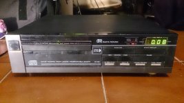
So, just a quick post to share a successful repair I just did to a Philips CD150 which I got for almost nothing, with the indication that it wouldn't read any CDs (showing Err). This turned out to be a hard one to diagnose and in the process I learned and discovered a lot about philips cdm transports and this player in particular, so I think this can be very useful for some people, although the player itself was kind of low-end at the time, it still sounds quite nice. If it was one of the better ones (let's say, TDA1541 at least), I'd now start modding it as I did with my Marantz, but like this, I'm simply going to sell it cheap. This was more for learning than anything else.
Here we go:
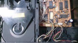
first things first - I opened it and cleaned the lens. Nothing improved.
I then took my mobile phone camera and "made a movie" of the laser lens when hitting play. It showed that nice tiny red dot and also the coil moving up and down, so laser and focus was working. Decided to clean inner lens (which is quite easy with the CDM laser head). No improvement.
Next, I searched the internet for the service manual (first I didn't get the manual for the CDM, only for the player). Found out about the three service positions. Tried them out and the player clearly passed stage 1 and 2, but then, the number 3 would sometimes appear very shortly but it would immediately stop and go back to 0. Sometimes even with the swing arm making a hard stop against the limit.
I tried the Fast forward and Backwards keys to move the swing arm, responded well, although sometimes would engage in a strange kind of "stutter", I mean, it seemed to get stuck, vibrating. Very odd.
I starting measuring, laser voltage seemed ok, although it would vary a lot, depending on the actual position/state, but I guess that's normal.
Measured all supply voltages and got kind of confused - it didn't measure +-9V, but +12 and -13V, which is very high for CDM, I think. So I (mistakenly, as I discovered later) thought there could be a problem with the power supply (transformer hums audibly), checked all, even changed the supply wiring to 240V (was 220V), didn't make a change, then I even built a little regulator circuit with LM317 and 337 to feed clean +9,5 and -9,5V to player, which turned out to be a waste of time - player behaved exactly the same way and the regulators would get hot, would need large heatsink, so I ditched this idea.
Next and after searching and reading a lot on the internet, I decided I would recap the servo board, as frequently the electrolytic caps have dried out, especially those blue Philips axial, the infamous C2103 especially. So I did this but nothing improved. Then, when I was trying to measure some stuff (was starting to think that the problem would be in the radial drive, for example the driver IC), while suddenly the player advanced to service position 3!! 😕 I was confused and surprised and immediatly decided to try it out to play a CD, connected to my amp, and well, it played! Music sounded good. But it stopped after 1 minute and didn't play again...
So, now I knew that the laser and transport should be fine, as well as the DAC and general control circuitry, although it still could be the radial drive or something, which caused it to loose tracking or not play at all.
I got myself the service manual of CDM-2, but then actually found out that this player had received a new laser head, the CDM-4, somewhere in the past, as the servo board was CDM-2/29, if I'm not mistaken right now, but the laser is CDM-4. This was interesting and I actually found the part where Philips indicates exactly what has to be modified to be able to make the CDM4 laser work with the old servo board. I checked all of the adaptations, I mean, I didn't know the history of this player, maybe adaptation was made wrongly? But no, all was exactly as in service manual.
I was getting a bit desperate and was running out of ideas. But then I had an idea: what if the player would need to warm up to be able to play? As I had it on when I was measuring for quite some time! Well, I left it on half an hour. And guess what? It worked! Not perfectly, but would play here and there.
I then searched the internet for this and found the solution: it appears that Philips at that time used so called "griplets", which seem to be a very frequent problem on more well known players like CD104, for example, and can cause all sort of problems which generally go away when player is warm. What seems to happen is that the solder in those griplets (which connect one plane of the PCB to the other) has cracks and doesn't conduct well anymore, while with heat and thermic expansion, it starts to conduct better.
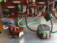
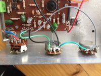
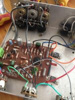
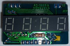
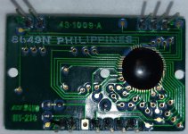
So I decided to take care of the main decoder board, as it was the only PCB with griplets and in the process also recap most of the electrolytics.
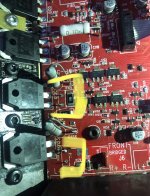
I didn't drill the griplets, as they recommend for CD104, as here each and every of them leads directly to ground plane and some have one leg of a capacitor in it, so I simply sucked out the old solder with desoldering pump and scratched a bit of the copper on the top layer to get the oxidation off and then put quite a lot of solder to reflow the whole griplet and solder to the scratched place to make sure it had good connection to top ground plane.
After all this, I tried it out (cold, obviously) and bingo!! Worked!!! 😀😀
I took the opportunity to verify laser voltage adjustment, which was perfect and made some other measurements, all checked out fine.
Problem solved! I tried it out with several different CDs, some pressed and also quite a few CD-R, it reads all of them, although it takes quite some time to read the TOC of a CD-R, which doesn't happen with pressed CDs, there it's very quick. Takes some 20 seconds to read TOC of some CD-Rs. But then plays them flawlessly, no skipping, and goes to all tracks, even 80 minutes CD. So I guess that's normal.
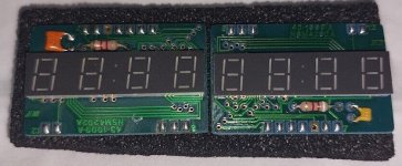
While testing, I also found another problem by mere chance (and am glad that I did!), one of the connectors to the display board was too loose, I tried contact spray and whatever, but it would loose contact when I'd touch the wires and scramble display and make controls not working. I decided to go the radical route - I just cut the wires and soldered them directly to the board. Problem fixed.
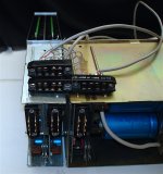
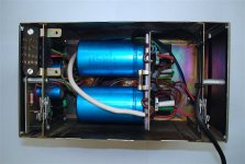
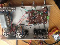
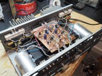
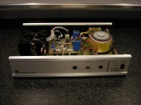
Ah, before I finish: I upgraded the power supply caps while recapping, put some much bigger ones. And I had to make the tray working again, with a new belt (not original, but works), but that strange door was causing problems (why did Philips make a door? had never seen this!), decided that the spring was too tight, so I simply cut a few of the windings of the spring so that door would stay shut but open much easier. Problem solved!
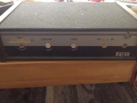
So, I now have a fully functional CD150 for sale, I'm listening to it as I'm writing this, sounds nice. Learned a lot with this one.
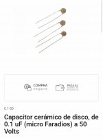
Ah, and last but not least: as I didn't have access to original Philips BC capacitors, which apparently are the best for that (in)famous C2103, I decided to install a 47uF capacitor of a not very well known and certainly not expensive brand. As I had read that it shouldn't have low ESR and that a bit more of capacity actually could be good. And well, it works perfectly, AFAIK, no reading or tracking problems and laser voltage stays precisely at 49,8 mV. Was I just lucky? Or is this capacitor not so critical in some of the players or, just an idea, if they are upgraded with CDM-4 on old servo board, as this one?
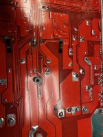
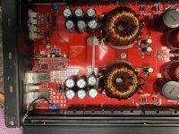
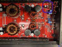
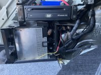
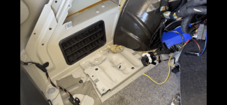
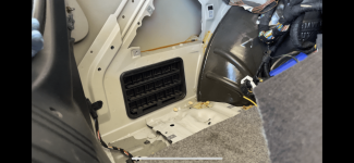
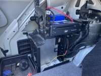
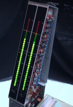
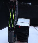
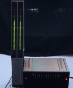
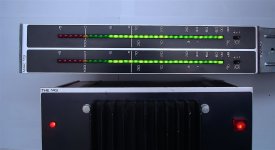
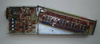
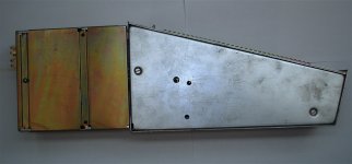
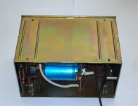
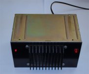
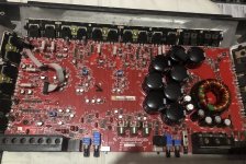
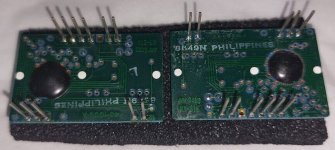
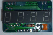
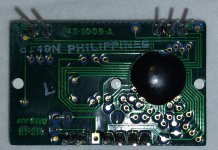
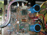
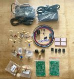
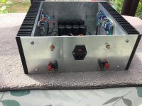
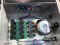
A couple of photos after cleaning, recap and player working fine (didn't take at details):
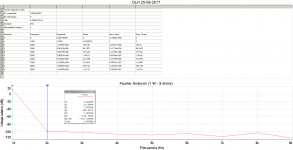 Fourier Analysis at 1W 8 ohms.png29.5 KB · Views: 7,447
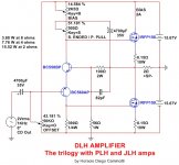 DLH Amplifier.jpg119.7 KB · Views: 7,772
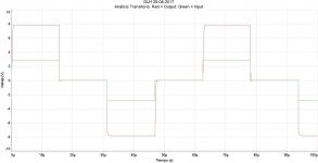 Transient Analysis.jpg275.7 KB · Views: 7,419
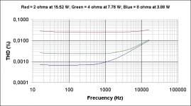 THD vs Frecuency.jpg135.6 KB · Views: 6,584
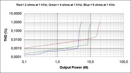 THD vs Output Power.jpg142 KB · Views: 6,394
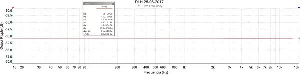 PSRR vs Frecuency.jpg248.4 KB · Views: 4,818
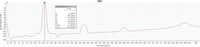 IMD at 2 ohms.jpg462.5 KB · Views: 4,531

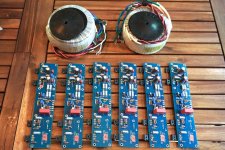


 Both concertos are dead now...


![IMG_20220709_122516102[1].jpg](/community/data/attachments/978/978975-c9306f16c69070ed40e447e9c0aeb2b5.jpg?hash=yTBvFsaQcO)
![IMG_20220709_125628529[1].jpg](/community/data/attachments/978/978976-f29acb52319702674c90c26135628fed.jpg?hash=8prLUjGXAm)
![IMG_20220709_124213930[1].jpg](/community/data/attachments/978/978977-c6533be40009f51a7c812d31c491e630.jpg?hash=xlM75AAJ9R)
![IMG_20220710_110636600[1].jpg](/community/data/attachments/978/978978-2f59bb720fdfdda76707228c3a74db54.jpg?hash=L1m7cg_f3a)
![IMG_20220710_110646590[1].jpg](/community/data/attachments/978/978979-be38d1a895d71c3e8a151070f5eeaf7e.jpg?hash=vjjRqJXXHD)


