Hi all,
Being personally fond of the sound of my UGS modules - nobody's perfect -, I wanted to test some ideas we've been talking about with my friend Philbyx, who owns the paternity of the idea
😉 His sharp neuronal connections made a link between the UGS schematic and the Zenquito, a french PP amp which seems to be quite highly appreciated from French DIYers (
http://perso.orange.fr/jm.plantefeve/sche.html). So we decided to take this concept further and, stimulated by the Aleph-X brainstorming, we began to test and build something.
A word of warning here : this beast uses the now infamous dual japanese JFets 2SK389/2SJ109. Shame on me, I know... But I had some of them... What else could I do ?
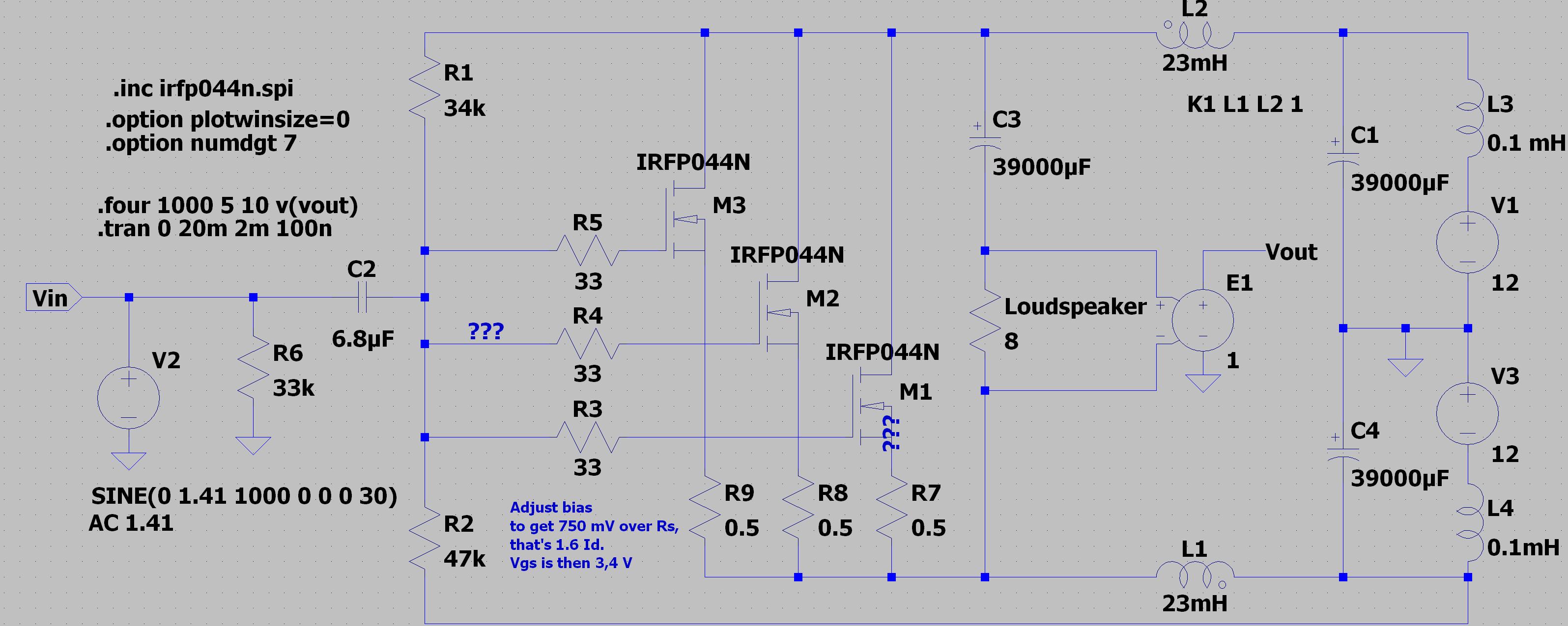
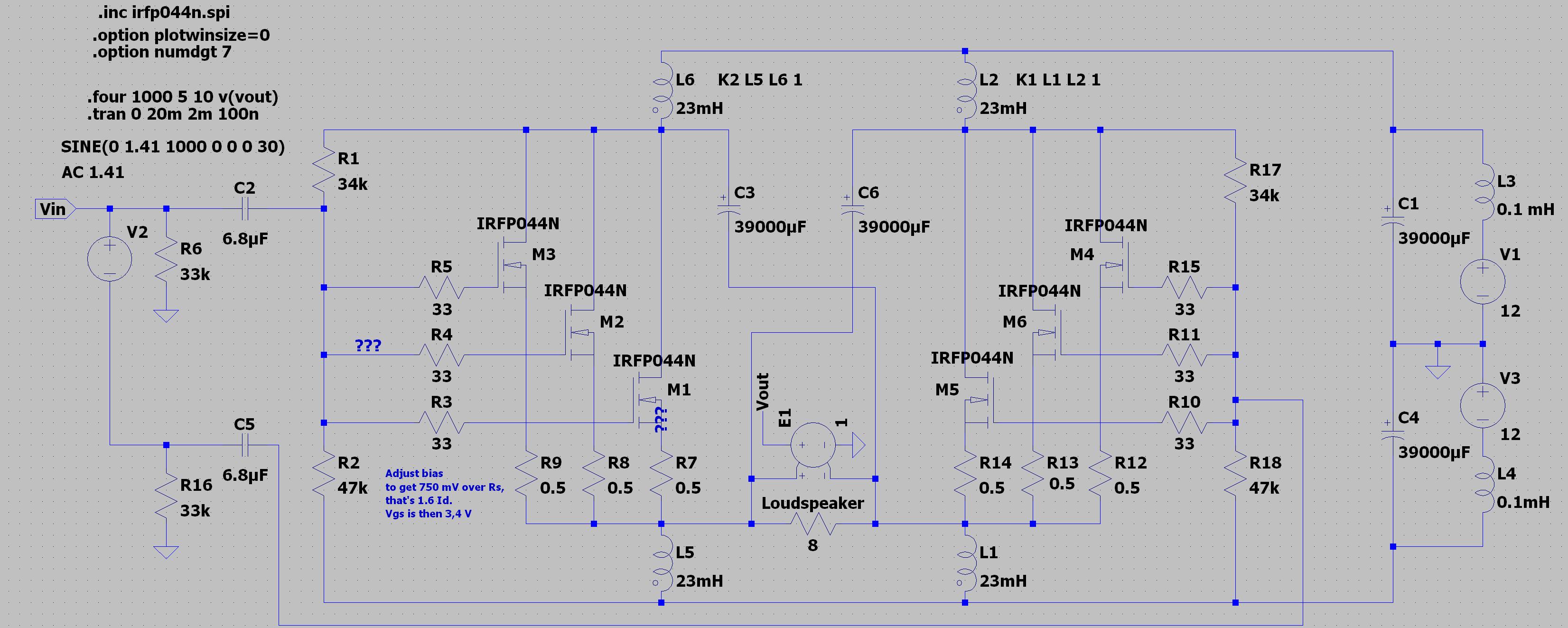
So here's what I finally came upon (see attached pdf)... Nothing very fancy or new, just basic building blocks put together. The front end is a basic current-mirror ugs, with increased current output capabilities to properly drive paralleled mosfets. The current mirror transistors have been changed to handle the power requirements, and I used 2SC2911/2SA1209 for their nice characteristics.
The front end is followed by a classical Vbe multiplier for biasing a typical triple pushpull of mosfets. I'd rather see this biasing stage as a kind of shunt regulator, but that's only a matter of words
🙂 I kept the resistor network at the output of the UGS to be able to test the difference between global and local feedback (using jumpers).
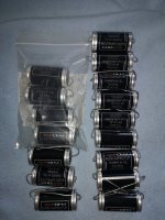
The power supply is built from a 2x18V 400VA transformer (1 per channel) with a CLC filter, giving a rough 23V at rails. The front end is powered a bit higher (30V) using a voltage doubler (à la A75
😉 ), followed by discrete regulators, to provide more output swing from the front end.
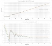
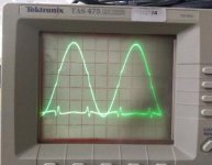
The mosfets are idling at 250/300mA each for the moment, and on the bench, the max output power (before clipping) is close to 100W in 8 Ohms. More than I need
😉
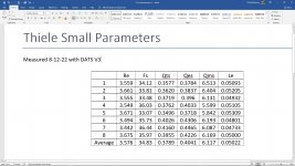
I've added an on board DC protection, but I must confess I'm amazed by the offset performances : under the mV on diff offset, and under 5mV on absolute offset...
😎
It's only at prototype stage for the moment, and I began the listening sessions comparing them to my Aleph X.
How to say... In a few words, the AX is rounder, warmer, softer... The U.P. is sharper, wider, faster. The AX gives a "classical" class A feeling, with warmth and lushness, but a bit of fuzzyness. The U.P. seems a bit "cold" in comparison, but seems to be more "balanced", in the sense that it does not seem to emphasis anything. It goes higher (some veil on the AX in comparison), is faster. The bass has a better slam than the AX which seems a bit slow here. And most of all, the U.P. is awesome on the spatialization. Not that it widens everything outrageously, but it's much more accurate and refined, much less fuzzy than the AX. Every frequency seem to be much more isolated and located...
Well, I'm not good at putting it in words, but both AX and U.P. are marvelous amps, and I will have hard times to chose. I still have some test to do on the feedback path (still haven't done extensive listening on the local feedback configuration).
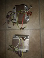
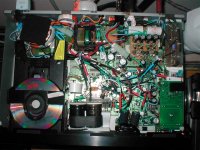
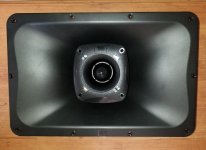
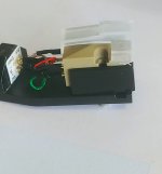
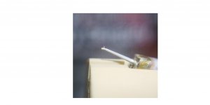
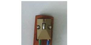
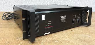
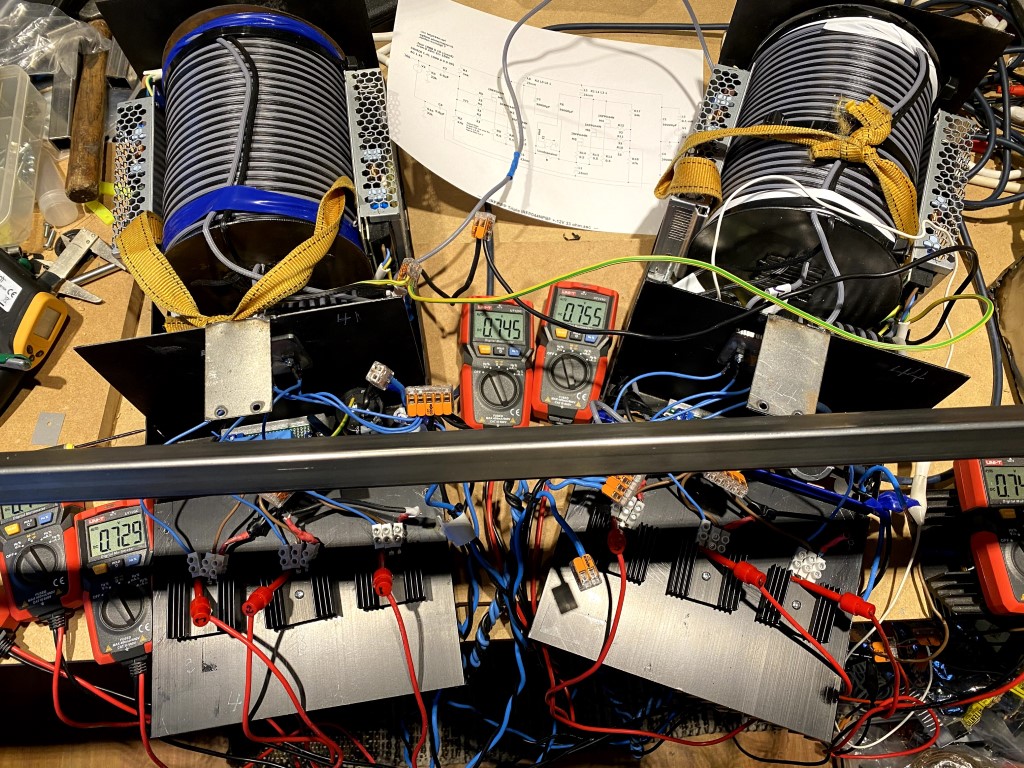
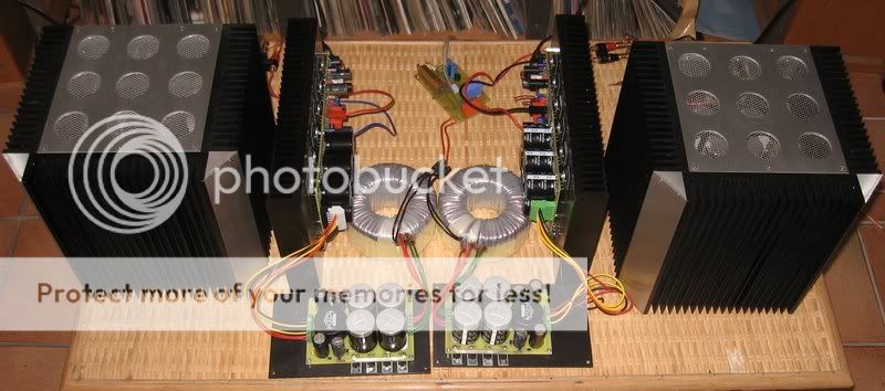
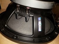
Some photographs of the beasts at work :
The AX/U.P. challenge
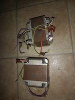
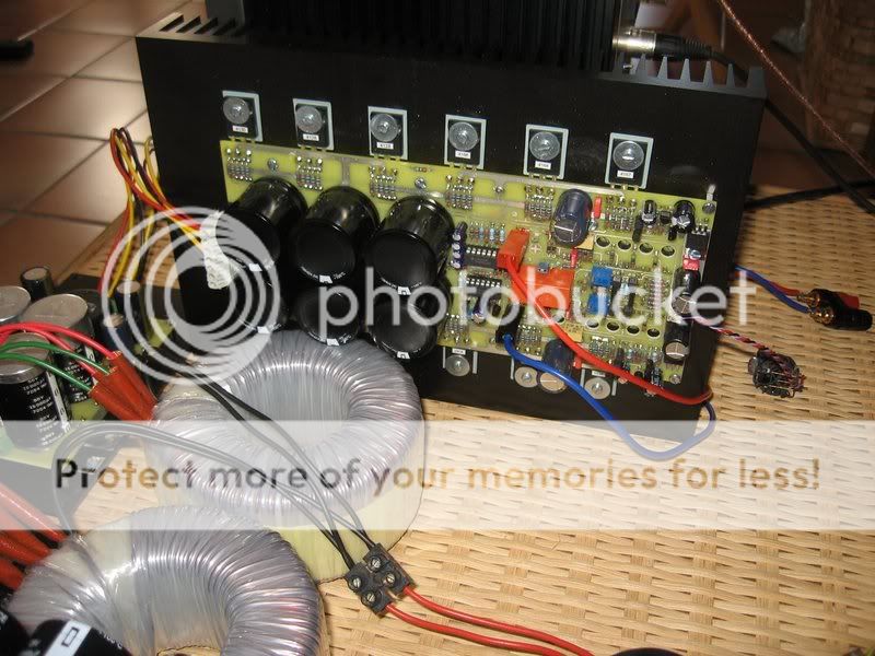
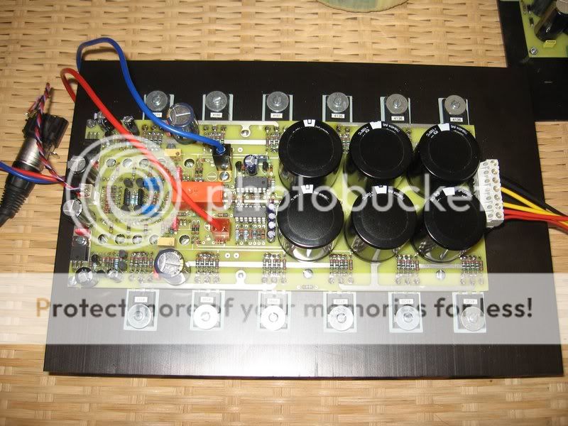
One channel :
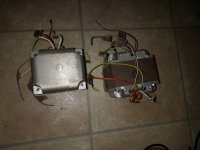
Closeup :
Once again, a zillion thanks to Nelson Pass for guiding us to the stratosphere
😎
And warm thanks to Philbyx
😉 Feel free to post your version here
🙂
Thanks also to Marc and Ninio, for supporting this without listening
😀 You'll be rewarded
🙂


![IMG_5195[1].JPG](/community/data/attachments/990/990643-d31dcf3bb503d81d75d678e565c1eaca.jpg?hash=0x3PO7UD2B)


