Just picked it up, no output. Found F601 Fuse blown so replaced that but same symptoms i.e. VU lights power up, but no output. No movement on meters with a known good line input and no headphone output either.
I can't hear the RY401 protection relay click and have measured voltages from the main transformer and 2 of the outputs are low (see pic). I suspect they're being dragged down but have no idea how to proceed?

I can't hear the RY401 protection relay click and have measured voltages from the main transformer and 2 of the outputs are low (see pic). I suspect they're being dragged down but have no idea how to proceed?
The most likely culprits are the two STK power packs, IC301 and IC302
Check pins 3 and 8 on each IC- they should be 0 volts. They are STK0040.
If they are not 0, then likely these are blown.
here is a thread on the topic
https://www.diyaudio.com/community/threads/testing-stk0040-ii-ics.271536/
Check pins 3 and 8 on each IC- they should be 0 volts. They are STK0040.
If they are not 0, then likely these are blown.
here is a thread on the topic
https://www.diyaudio.com/community/threads/testing-stk0040-ii-ics.271536/
Thanks for the prompt reply, and the link to test the IC's.
Taken from the other post, here are my values (in brackets);
Pin 1 = -1.2V (-1.2)
P2 = -35V (-37)
P3 = -0.02V (-0.027)
P4 = 0V (0)
P5 = 0V (0)
P6 = 0V (0)
P7 = 0V (0)
P8 = +0.02V (0.027)
P9 = +35V (37)
P0 = +1.2V (1.2)
They all appear to be good except the 37v rail is a bit too high.
Taken from the other post, here are my values (in brackets);
Pin 1 = -1.2V (-1.2)
P2 = -35V (-37)
P3 = -0.02V (-0.027)
P4 = 0V (0)
P5 = 0V (0)
P6 = 0V (0)
P7 = 0V (0)
P8 = +0.02V (0.027)
P9 = +35V (37)
P0 = +1.2V (1.2)
They all appear to be good except the 37v rail is a bit too high.
I'm thinking these 2 pins are the coil side of the relay? Not a sniff of any voltage here.
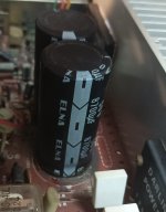
No oscilloscope. I think the main caps have been replaced at some point - see pic?
Pin 6 on IC401 should read 1.1v but has 37v on it!
No oscilloscope. I think the main caps have been replaced at some point - see pic?
Pin 6 on IC401 should read 1.1v but has 37v on it!
Attachments
I thought all the other pins on IC401 are within tolerance, but having re-checked, Pin 1 should be -0.6v, but it's actually reading +0.6v. The rest of the pins are as per the attached apart from pin 6.check pins 1,2, and 3on IC401
The caps look like the originals- if you replace go to 10k or higher (12k or 15k)and either 50v or 63v depending on what will fit.
Thanks for your help, btw. Much appreciated.
Attachments
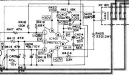
I suggest replacing all the electro caps around IC 401, as I have had these fail before with similar results, C404 should be replaced with a polyester film cap, and the others C405/C406 and C407 with low impedance electrolytic types (similar to Nichicon UPW). Also check that diode D403 is OK (use a DMM in diode test mode with one leg of the diode lifted from the PCB). At this stage you might want to consider replacing the relay as well- The replacement is an Omron MY4-02-DC24 with the 4 N/C pins chopped off.
Then we should know that the protection circuit is working
I have benefited from the assistance here many times, so happy to help. It is a while since I did a JAS 22.
Then we should know that the protection circuit is working
I have benefited from the assistance here many times, so happy to help. It is a while since I did a JAS 22.
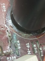
That cap is broken. Move it out as soon as possible, make a goood cleaning, check the contacts. Electrolyte has damaged bridging wires, imagine what can it do to thinny tracks. As a bonus, electrolyte can make the short circuit, nice sparks and burns on surface.Thank you. This is a better pic of the caps - looks like electrolyte has leaked at some point, but the caps look in great shape. Is there an easy way to test these apart from looking for a short?
I would change all elcos though.
So, when I bought it, the last owner said they had had it repaired a few years ago, but didn't know what had been replaced. It then failed again recently, so they sold it.
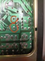
A cursory look at the soldering suggests the L301 coil has been either replaced or resoldered. I can't actually tell if the C603/4 large caps have been replaced, but I'm getting different Ohm readings from both so I guess I should replace them and clean up that whole area?
Is there a better cap to replace those or are they good if I can find a like for like - they state 8700uF / 50V. The factory manual doesn't state what these should be.
I did read that JVC often used a thick glue to hold the larger caps in place - could this be what the brown stuff actually is?
Ok, so the factory manual says electrolytic for the C404 and I'm having issues finding a 50V rated polyester. How important is this and what's the reasoning behind the choice of polyester?I suggest replacing all the electro caps around IC 401, as I have had these fail before with similar results, C404 should be replaced with a polyester film cap, and the others C405/C406 and C407 with low impedance electrolytic types (similar to Nichicon UPW). Also check that diode D403 is OK (use a DMM in diode test mode with one leg of the diode lifted from the PCB).
In fact, when I look at the actual cct board, both C404 and C408 are not present, and the soldering underneath suggests that's how it cam from the factory (a consistent dull finish). Now I'm confused - was there a difference for european markets?
Last edited:
One of the boards (nearest the front) is marked TXX-135-E-1 but I can't find any similar TXX number on the main power boards - the only thing I can see is TP-N4-T and E10271-001Is it for european market sold? The PCB should be marked TXX-136-E-1.
But yes, it's a European model.
Last edited:
Ah, yes, it can be the glue. But it should be cleaned anyway. It changes chemistry with time and tends to damage components.
They didn't expect it to last so long")
Elkos should be renewed with the time also. It is not big problem if little bit more uF, and bigger voltage is not problem at all. Let's say 10 000u/63V should be ok if fits, but no more than 10 000u.
Than you should check voltages. If ok than you should check signal on different points. What do you have for test/measurement equipment?
They didn't expect it to last so long
Elkos should be renewed with the time also. It is not big problem if little bit more uF, and bigger voltage is not problem at all. Let's say 10 000u/63V should be ok if fits, but no more than 10 000u.
Than you should check voltages. If ok than you should check signal on different points. What do you have for test/measurement equipment?
The "E" confirms it's for european market: so the missing components are really not missing. Less capacitors to change. As already said, the first place to check are the capacitors/IC of the protection-relay circuit.One of the boards (nearest the front) is marked TXX-135-E-1 but I can't find any similar TXX number on the main power boards - the only thing I can see is TP-N4-T and E10271-001
But yes, it's a European model.
Great, at least now I have an action plan i.e. change the main 2 caps and the other smaller ones around the protection relay cct.The "E" confirms it's for european market: so the missing components are really not missing. Less capacitors to change. As already said, the first place to check are the capacitors/IC of the protection-relay circuit.
Would the voltages be different without the 'missing' caps?

- Home
- Amplifiers
- Solid State
- Help with JVC JA-S22 please