GaN-based class D amplifier PWM vs Delta-Sigma? Closed Loop vs Open?

Hello everyone, I am a university student working within a group of three on the design of a class D amp as a graduation project, with the end of goal of automobile application. At the moment, we are in the early pre-design stage which entails considering relevant design options for different aspects of the amplifier.

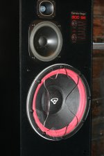
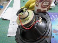
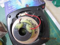
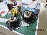
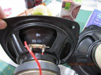
For the transistors we are using LMG3422R030 GaN transistors capable of operating at a switching frequency of over 1 MHz (copy of the datasheet attached below). We are aiming for a 500W output power on an 8 ohm loudspeaker with as minimal THD as possible without compromising efficiency. After evaluating bridge designs, we have settled on the full bridge design.

These are our main unresolved design concerns as of yet:
1. Modulation scheme: PWM compared to Sigma-Delta
2. Open Loop design compared to Closed Loop design

If possible, references and resources would be much appreciated.

Attachments

DEF Amp

I am going to start this thread around the circuit shown at BAF 2016,
seen at the end of the talk on the video, and attached here in simplified
form.

I am calling it DEF, which stands for Depletion / Enhancement Follower.
It is a self-biasing push-pull output stage which has some interesting
characteristics, not the least of which is low temperature drift which allows
stable undegenerated operation.

:wiz:

Attachments

  • DEF.jpg
    DEF.jpg
    203.4 KB · Views: 7,847
  • Like
Reactions: myfirstamplifier

Combining Raspberry Pi with audio CD drive

Hi,


I'm building digital music players based on the Raspberry Pi for retrofitting audio equipment (internet radio capability, streaming music from the NAS, better GUI, more functionality). I'm already able to play Audio CDs with a standard USB CD-drive (using VLC) but the startup is slow (detecting the type of CD), the speed too high (can be reduced by using Setcd), in the end it's not playing a good old audio CD.


Now I would like to combine the Raspberry Pi with a CD mechanism. I already learned that the mechanics with laser pickup and the two motors for spindle and rotation are available as spare parts. Whats missing is a control board with the interfaces to the CD mechanics (laser pickup + the motors) and to the Raspberry PI (I2S digital audio signal and control interface with SPI or I2C).


I already found an IC (Onsemi LC78615E) which integrates this functionality. But I didn't found a ready PCB either for this chip or something similar.


My questions:

  • has anyone experience with this topic (interfacing Raspberry PI with I2C and SPI/I2C with a conventional CD mechanics)
  • are there PCBs available?
Would really be great if I can get some information here.


Edwin

FS Interstage Transformer Monolith Magnetics IT01/18mA new pair!

hi all, Selling the following:

pair of Interstage Transformer Monolith Magnetics IT01. Both transformers are new.
Version: Hi-B grain-oriented FeSi dual C-core, air gap for 18mA, ~125Hy(primary inductance)
Datasheet: https://www.monolithmagnetics.com/sites/default/files/IT-01_25.pdf

Items are located in Germany and will ship in EU.

--450€-- shipping included

payment via paypal (pay for friends) or bank transfer

Attachments

  • 01_IMG-1391.JPG
    01_IMG-1391.JPG
    545.6 KB · Views: 156
  • 02_IMG-1392.JPG
    02_IMG-1392.JPG
    542.2 KB · Views: 138
  • 03_IMG-1393.JPG
    03_IMG-1393.JPG
    492.2 KB · Views: 148
  • 04_IMG-1394.JPG
    04_IMG-1394.JPG
    586.7 KB · Views: 164

Luxman R-1050 Sound only coming from one channel

Hello DiyAudio members.
Looking for a little help.
First, I am new to DIY on receivers.
I have a Luxman R-1050.
Everything was working fine then suddenly for the past week sound is only coming from one side.
Doesn't matter if I am on FM/AM or phono. Sound only comes from the one side. Switch the connections on the speakers just to prove it wasn't a speaker problem.
The channel lights seem to indicate that sound should be coming from both channels..
Kinda of hoping one of you experts have seen this before and you are going to tell me to clean a switch or two..
P.S.. No videos of anyone restoring a Luxman 1050 out there.. To bad 😭

Thanks for the help.

Ω Rating on Resistor unclear???

Hi.

I'm working on a schematic of the existing crossover associated with the Rotel RL-870 Loudspeakers.

Attached is a photo of the sandcast resistors

Instead of a value appearing next to the Ω symbol, there appears to be a W "WΩ" ???

The resistor is ALSO marked " 3R3-J 3W-K-8 "

Is there enough information on this resistor to identify its Ω value?

Attachments

  • Rotel RL 870 11.jpg
    Rotel RL 870 11.jpg
    356.5 KB · Views: 144

Juggling Midrange Location in a Unity Horn

Last week I tried an experiment with one of my Unity horns that worked out alright. I thought I'd document the results:

In the commercial Synergy horns, the midrange taps are located approximately 3.5" from the throat. This location is based on a series of criteria:

3) the area of the horn at the location of the taps
2) the desired crossover between midrange and tweeter
1) the geometry of the compression driver

It's really hard to go wrong if you put the midrange taps 3.5" away from the throat, and if you don't want to crunch the numbers that's a perfectly good place to put them.

Arguably, the most important variable here is the area of the horn at the location of the taps. The reason that this variable is so important is because you don't want to have a compression ratio that's too high. For instance, you might think to yourself, "Why don't I just put the midrange taps as close as I possibly can? What could go wrong?

The problem with putting the midrange taps too close to the throat is that the compression ratio will be sky-high, and that will lead to huge distortion figures. I found this out the hard way once, I built a couple of front-loaded-horns using the B&C 8NDL51 and I had a compression ratio that was over ten-to-one. Everything sounded fine at low levels, but once you gave them even ten watts of power, the horn made a cracking noise that sounded like the 8NDL51s were trying to split the walls of the horn.

And now, the Regulator-Chip JLH Amp.

After the Regulator Chip Amp and the Chtringlunator, it is time to translate the JLH topology into voltage regulators (I hope JLH won't be turning in his grave).

The task is pretty straightforward, and the results are excellent.
And since the circuit operates in class A, it doesn't have slew-rate issues.

In practice, R2 and R9 can be halved: the spice model I have for the LM317 reaches its current limit at only 850mA, about half the actual device. This will make the amplifier able to drive a 4 ohm load.

Pics will follow.

Attachments

  • VregChipAmpJLH.GIF
    VregChipAmpJLH.GIF
    37.2 KB · Views: 2,575
  • Like
Reactions: Bonsai

The Beatles "Revolver" 2022 Re-Issue

Bought the 2 CD version of this album today; really enjoying the new mixes and early takes.

At first hearing, some remixes work better than others, with perhaps too much bass on She Said and Yellow Submarine which muddies the vocals a little. I'm Only Sleeping really stands out, sounding more funky due to the clearer bass. Ringo's cymbals are a little muted on some tracks, again, as in She Said She Said, but the overall drum sound has more impact than previous issues, particularly on I Want to Tell You and Good-day Sunshine.

I really like the way you no longer have voices from one channel and instruments on the other. Instruments, such as the French Horn on 'For No One' are clearer due to the new mix. Good-day Sunshine seems to have more 'oomph', etc etc.

Is it 'better' than the 2009 stereo issue, the original release or the mono; I don't know, but I find it more enjoyable.

The 2 CD issue includes stereo versions of Paperback Writer and Rain, plus early takes, mainly before additional overdubs and instruments were added. The horn-free 'Got To Get You Into My Life' comes across as harder rocking.

Fascinating extras, but not essential. Nice booklet, too.

Other views?

Geoff
  • Like
Reactions: IamJF and kevinkr

Lucas from Nebraska USA

Hello everyone,

I am relatively young in the audiophile world, with my main spending habits being headphones and more convenient audio. I currently own a Schiit stack and run a pair of Hifiman Sundaras and a pair of Meze 99 Classics.

I've recently gained interest in amplifier repair and am interested in building a DIY foam panel speaker.

Login to view embedded media

Tpa3116d2 Amplifier Board Connection Diagram

Hai Friends, Today In This Article We Are Going To See This Tpa3116d2 Ic-Based 5.1 Class D, Amplifier Board.


tpa3116d2

This Board Is Very Compact So You Can Assemble A 5.1 Amplifier With A Mini And Compact Cabinet.
This Board Has Six-Channel Input And 6 Channel Output. You Can Get 50 Watts Of Audio Power Output Per Channel.

For This Board You Should Use Only Four Ohms Speakers And Subwoofers… If You Are Using An 8 Ohms Speaker Then The Audio Result Will Be Low.
So You Should Compulsorily Use 4 Ohms, Speakers, With This Amplifier Board.

tpa311d2

This Board Works With A Single Supply Dc. For Better Audio Quality And Results Use A 24v 10 Amps SMPS. Or A 20v 10 Amps Transformer. (SMPS Supply Is Best For Audio Results)

tpa3116d2

If You Are Not Happy With This 50w Subwoofer Output… You Can Use This Tpa3116d2 Class D Mono Amplifier Board. This Mono Amplifier Board Can Get A Maximum Of 100watts Audio Power Output Per Channel. If You Are Using This Tpa3116d2 Mono Amplifier Board You Should Use A 2 Ohms Subwoofer For The Best Audio Result. If You Don’t Have A 2 Ohms Speaker Then You Can Use Two 4-Inch Subwoofers With A Parallel Connection.
If You Are Ok With 50watts Power Output Then This Single Board Is Fair Enough For You.

tpa3116d2

This Board Has Many Safety Protections

  • Speaker Terminal Short Circuit Protection
  • Input Signal Over And Under Gain Protection
  • Speaker Terminal Power Supply Short Protection
  • Input Power Supply Low And High Protection(Below 10v To Above 30v) So Always Use The Recommended Power Supply To This Board For Longer Ic Life Below 30v.

Now We Are Going To See This Tpa3116d2 Board Input And Output Connection Details​

tpa3116d2
tpa3116d2


Audio Output Connection Details
All The Connections Are Clearly Mentioned On This PCB Board.

After All, Connections Are Done Always Switch On This Amplifier With A 100w Bulb Based Series Connection. Because If You Give The Wrong Connection Then The Bulb Will Glow So Your Board Will Be Safe. If The Bulb Is Not Glowing Then You Are Giving The Right Connection To The Board. Always Remember This Method For All Your Boards Before Turning On Your Amplifier.

Click Here To See The Tpa3116d2 Ic Datasheet

So That’s All Friends, If You Want This Board You Can Ask Me In The Comment Section Below…
And If You Have Any Questions About This Board Then You Can Ask Me In The Comment Section…

"Le Mutant" Class A

Attached is a pic of a new Class A amp prototype inspired by my work with the "Half Nelson" amp described elsewhere in the Pass Labs forum, and also as a result of a little email back-and-forth between me and Papa after last year's Burning Amp. It solves a few of the problems I encountered with the Half Nelson, at the cost of a tiny bit of extra complexity (actually, the parts count is probably very similar between the two - I'd have to open up both schematics and do a head count).The new design also eliminated a lot of nasty coupling caps.Schematic will follow when I get the thing powered up and nail down the bias values. I'm also working on a version of the Half Nelson using the Semisouth R085 jfet, but that one is on hold for a while, as this amp may be easier to spit out. I'm also working on a tube-type design using an R085, but that will be the subject of another thread. Burning Amp should be interesting this year...

Attachments

  • Mvc-455f.jpg
    Mvc-455f.jpg
    36.8 KB · Views: 4,333
  • Like
Reactions: decramer

GREETINGS from Hawaii, Any AUDIOMOBILE GURUS out there? I need help. Schematics and advice in regards to MOTORBOATING on a channel of my SA 1000 amp

Greetings, I seek anyone here that has experience with AUDIOMOBILE gear from the late 70's... Especially needed is schematics and any possible info I can use to get this SA 1000 amp 100% again. Anybody have GEAR?... Might be interested here... an easy SWAP would be nice. It's currently FULLY operational BUT upon hard gain and EQ settings I get a SQUEAL, high pitched, and also motorboating from the BASS end. Only ONE channel of the amp is doing this, the other 5 channels seem fine. NOT the EQ at this point, I THINK its a single channel in one amp thats the culprit.... FLYING BLIND here.... LOL. LMK... Thanks BDBD/2022

Universal remote to control TV, Apple TV, & Hypex FA123

I have a modest home theater setup:
  • LG OLED655C8PUA TV
  • Apple TV as streaming source
  • Hypex FA123 amps (connected by optical out from the LG TV)
  • DMLs as external speakers
I have the Hypex Infra red remote controller for the amps.

This leaves me with 3 remote controls.

I can control most of the day-to-day Apple TV functions with the LG TV's "Magic Remote".
No way exists (that I have found) to control the Hypex amps with either the Apple TV remote or the LG TV remote.

I'd very much like to control the three devices with a single remote control.

The attached shows the Phillips RC5 (IR) codes for the Hypex remote.

When I asked Hypex support, whether they could recommend a universal remote I received the following:
I only know of one customer who had sent his OneForAll Evolve to OneForAll HQ for programming the codes. I’d suppose they have added it to their database afterwards but I cannot find any devices under Hypex in their database. And I thought we were in the Harmony database but I don’t know under which device.
Unfortunately, neither OneForAll nor Harmony have listings for anything Hypex or the Fusion line of amps.

This leaves me needing a universal remote that can "learn" the Hypex remotes functions as well as the LG TV's and Apple TV's.

Any recommendations for such a remote and how to configure it - to do what I need - appreciated.

Also, if anyone has a better suggestion for where on the site this question ought to go, please advise.

Attachments

  • Screenshot 2022-11-11 at 5.16.59 PM.png
    Screenshot 2022-11-11 at 5.16.59 PM.png
    19.1 KB · Views: 93

Skar 2000.1d resistor

So I recently purchased a skar 2000.1d, knowing it had been damaged. The output had been shorted out at almost max output, yet the damaged was surprisingly minimal. There is however a resistor that burnt up, and I've had no luck finding any schematics, and simply got PFO'd when I reached out to skar. Does anyone have one of these handy that can take a look for me? It appears to be labeled R99. I hope this is in the right section. Thank you all for reading!

Attachments

  • Screenshot_20221112-040055.png
    Screenshot_20221112-040055.png
    517 KB · Views: 144
  • Screenshot_20221112-040031.png
    Screenshot_20221112-040031.png
    421.3 KB · Views: 129

Electro Voice SP8B vs. SP8C

The short form data of SP8C/SP12C/SP15A are here
https://products.electrovoice.com/binary/SP8C, 12C, 15A EDS.pdf
Unfortunately there are no datasheet of the SP8B online.
Maybe the SP8B use an ANiCo magnet drive unit.

Here are some images online
Building with E-V SP8B
EV SP8B Electro-Voice Vintage Speaker 8" Full Range Whizzer Alnico OHIO | #287161236
retro vintage modern hi-fi: ElectroVoice Popular Electronics Ad October 1955 | Vintage speakers, Speaker plans, Hifi
1961 Ampex Branded 8" 16ohm Electro-Voice SP8B from 8202 Signature Console Photo #2368348 - Canuck Audio Mart
(ampex branded version without whizzer cone)
https://www.canuckaudiomart.com/details/649141966-electro-voice-sp8b/images/798821/

Thank you for upload a datasheet of the predecessor of SP8C and calling some commercial spraker box models equipped with this transducers.

Yamaha CX-630 No Volume or Tone Controls

Hi guys, I'm hoping someone can help me with this one.

I'm repairing a Yamaha Natural Sound Control Amp CX-630, it was previously making a horrible DC like cone thumping noise. And after reflowing lots of cold joints especially around Q71/Q72 it came back to life, that is almost.

I've connected it up to a Yamaha AX-400 amp and can hear the music fine but only if the volume on the AX-400 is turned all the way up and the volume on the CX-630 isn't working. Neither are the balance, bass, treble etc, and stranger still when I change the input selection with music playing it doesn't change the music plays on any input selection! The CX-630 goes with a friend's Yamaha model YST-A5.

Any ideas?

Rip Off E/Bay - join the boycott

Hi, I have just bought an item of of E/Bay on Sept 10th, with the seller only allowing shipping overseas via this Rip Off ''Global Shipping Program''.

The impression is that it is a fast safe service.

However the item cost $100 to ship & I now been advised I will not receive it until early Dec.

I have many times shipped to the US for a similar size & heavier weight item for just $65 & it gets there in 10 to 15 days.

I also can order & have ordered items from Ali Express that cost a fraction of that price & often I get them in 3 to 4 weeks.

I have now started advised sellers of item I am interested in, That I will not make a bid if they do not offer other postal options.
Please join the campaign & insist to not use Global shipping. Remember the power is in the consumer.

For comparison, on the same day I ordered a cart from the UK which was sent via 1st class mail. It arrived in 10 days!!

Cheers

Push pull buffer bias

Hello everyone,

I have a question about the push-pull buffer below. It is biased by a voltage divider so it can be run from a single supply. Now there is a 100k resistor between the bases and the voltage divider, but suppose I want to increase the input impedance, is there an objection to put a 1meg resistor or even higher?

1668959054800.png

Attachments

  • 1668958729773.png
    1668958729773.png
    5.9 KB · Views: 241

How to use bluetooth zlx12BT with subs

Hi, i just bought a pair of EV ZLX12 speakers. 1 is with bluetooth the other is not. When phone is paired with BT (left), i can set the mix out to R and use XLR to send R channel to 2nd speaker to get stereo. Now let's add subs.

My subs are DIY bass horns powered by XLS1500. If i had a mixer, or wanted to use RCA or XLR or even 1/4" input (e.g. from mixer) i would connect source to XLS1500 and use the link/out to each speaker to get stereo.

But if i wanted to use phone with BT, how would i do it with subs? Obviously with BT i have to connect to the L speaker. But theres only 1 mix out on the ZLX12BT so that has to go to R speaker to get stereo. So the only possible line out to sub amp would be the mix out from R speaker. So my sub channel will only be mono, from the R channel.

I guess now my question is, is that ok? It should be ok if i can assume that all content under 100hz will be mono at the source anyway. In which case maybe all that means is i would need to increase the gain at the sub amp by a factor of 2, to get back to the level as if i did input stereo to the amp. Does that make sense?

Is sub bass in music usually/often/always recorded as mono? Or is my assumption false.?

Hafler DH101 preamp repair and mods?

I've just purchased a Hafler DH101 preamp kit build. It is in decent working order, however, there is some "bleeding" of input sources. What I mean by that is that I can hear the aux and tape sources (if they are active) while listening to phono. Can anyone recomend what to look for to cure this problem? Also, i was wondering if anyone could recomend some mods. I read something about a moving coil upgrade, but i'm not sure what that is or how it would benefit me.

3.5/4 way loudspeakers insanity check

Hi all
I know, I know this mide be way out of league but I'm gonna build it anyway 😉
I'm not an expert in any way, but I have make couple speakers and they did sound nice to me.
Now as time goes by, I'm starting to lose interest in diy so this will probably be my last diy project...At least I hope as one is more expensive than the previous one 😉

In a couple days I will start making test cabinets but would like, if someone has time to check my plans about volume for drivers and spacing between those. I would appreciate it.

Below you will find pictures of concept design.
One is a classic box, and the other is a box with tweeter on top to have the option for sliding it forward and back for time alignment (not important as I have DSP..but it look's cool to me 😉.
Front baffle is at 5* angle but tweeter is not angled.

At first I liked the option with tweeter on top, but leter I prefer a more classical design...will see....

Thas will be fully active, analog precision DSP, hypex, SB acoustics with RAAL drivers, all in closed boxes ;
in a 3-4 Litres closed box
- 2 X Satori textreme MW19TX-8 + second channel of NC252MP / satori-mw19tx-8-textreme
in a like 9 litres per driver, total around 18-20L closed box
- 2 X SBA subwoofers SW26DBAC76-8 / sw26dbac76-8
dual oposite subwoofers in like 20 litres closed box with linkwitz transform (like 9-10 litres per driver)

Crossover points would bi like ;
  • sub / 19TX - around 80-85Hz
  • 19TX / 13TX - around 500-600Hz ( at about baffle diffraction point ?)
  • 13TX / RAAL - from 1.7-2.4kHz will see what sound best

Baffle wide is 220 mm.

What do you think ?
What about driver spacing between drivers in dependence of crossover frequencies ?
RAAL advise me to place center of tweeter at around 95 cm.


And one question how to place all those amplifiers on a plate.
Option A when I have power supply of NC252 and NC500 facing to the top and bottom of plate - speaker cables will cross each other
Option B when I have NC252 and NC500 power supply facing each other - the interconnection cable for subwoofers will be a little longer run by the power supply. Don't know if there will be any interference.

For me option A looks like a safer bet, but option B would be easier to connect once they are inside the cabinet...or not...😉

Please don't be hard on me, I'm not an expert, and I'm doing my best to not become one 😉
Will play with baffle design around tweeter, to achieve something like wave guide or not...will play and will se where it will take me...
The look is like 90% of the sound so 😉, it's more important how it looks then the sound of it 😀

Here is a video of my previous build, so I'm not total noob, but... VIDEO 1 or VIDEO 2

Attachments

  • 001.jpg
    001.jpg
    111.1 KB · Views: 207
  • 002.jpg
    002.jpg
    66.7 KB · Views: 168
  • 003.jpg
    003.jpg
    40.1 KB · Views: 144
  • 004.jpg
    004.jpg
    42.5 KB · Views: 151
  • 005.jpg
    005.jpg
    22.1 KB · Views: 165
  • 006.jpg
    006.jpg
    54.1 KB · Views: 162
  • 010.jpg
    010.jpg
    65.5 KB · Views: 194
  • 020.jpg
    020.jpg
    150.7 KB · Views: 183

DIY woofer wave guides, They work!

Hey everyone,

I just wanted to share this one. I was looking into ways to improve dispersion of large diameter woofers to increase the crossover frequency. I have a set of Cerwin Vega 300 SE speakers for playing around with. They are perfect because the woofers are run full range.

I used a piece of 3/8 cast acrylic, cut it out with a jigsaw. Flame polished the edges and used a propane torch to bend the middle in. I'll post the template.

The results are better than I expected. The waveguides completely removed the 7db peak at 1.5k. the speakers sound much more open and the sweet spot has changed from about 12" to several feet. I didn't do much off axis measuring, since I was using my laptop for the tone generator and it just didn't have enough output to get any consistent results.

I thought the results where pretty amazing so I had my wife come in, and do a blind A-B comparison. She said the one sounded richer, so the wave guides have 2 positive votes. I think these could be the answer for a lot of problems.

Jordon

Attachments

  • 12 woofer wave guide.pdf
    12 woofer wave guide.pdf
    4.3 KB · Views: 397
  • cerwin vega waveguide diy (2).jpg
    cerwin vega waveguide diy (2).jpg
    478.8 KB · Views: 1,859
  • cerwin vega waveguide diy (1).jpg
    cerwin vega waveguide diy (1).jpg
    536.3 KB · Views: 1,783
  • Like
Reactions: deanznz

What if more power needed ?

Simple ... I am in love with the P3A there is no other way arround that .
if the application is ok with 60-100W then so far there is nothing better in my world .....
Before many of you start to say things remeber that in my shop we repair an also listen audio machines
now days between 2500-3000 machines per year
that means that i have been listening the latest 10 years anything that is available , any topology any make, any brand , just say it and we already done it , and obvioulsy not once and not twice ....
I can remind you the reasons because some of us tent to forget why
Smaller amps requiere less safety measures ( vi limiters , miller compensations and so on )
mutliple tranistors suffer from times* the device capacitance so driver stage need to provide the current but also the ability to drive that much of capacitive load
Multiple active devices in the output there no guarantee that will "ring" at the same time .... The more the outputs then amplfier is more pcb depending
Thermals is an issue , rail distribution is an issue , decoupling is an issue , too many active devices and oscilation is waiting for you in the corner
you start with 200-300 MHZ ltp , then you might get away with 100 mhz VAS and drivers and then 30MHZ outputs
made a P3a ltp 300 mhz vas and drivers 200 and outputs 50 mhz just to examine the stability of the circuit
no problems at all and let us not forget that i have been messing around of limmits with the miller compensation
So if you sum those details and add to them minnor refinements that i ve made in the P3A this in total is what makes the P3A the amplifier that fits the picture
remember that other similar EFP amplifiers might preform alike, close or even better but the bootstrap in combination with CFP when it come to sound is unbeatable cobination any way you slice it .
there is a possibilty that a diamond input and a more in generall sophisticated input scheme or + and -VAS will provide precision but the result doesnt give the same feeling
Listeners say that the original combo playes better
But through the years and long discussions about that, obviously we have been there before and more than once .
----------------------------------------------------------------------------------------------------------------------------------
So today's question is "what if more power is needed ? )
there hass been an issue before and if i recall correct you can double the outputs as long as you add 0.47 /5W to every emmiter
i am not sure i want or like that
i could risk to skip that step and go with very close matching on the outputs fit them in a thick fin of alouminoum before the heatsink one on the lower side one on the upper side for the PNP and the NPN alike
That is to ensure that each pair shares the same temperature add that most of them i go with relatively hi bias so that prevents in away that outputs will act diferent

Any other ideas to squeeze more power ?

Automatic resonance frequency finder

Here is a fun application of a chipamp:

This little circuit is a sinusoidal oscillator that will adapt itself to the resonance frequency, impedance and Q of any driver presented to its test terminals.

It makes the measurement of said frequency fast, easy and accurate.

It could also find other applications: breaking-in of new speakers for example, or as a musical instrument with a variable length tube as resonator.

Have fun!

Attachments

  • FoFinder.png
    FoFinder.png
    16.8 KB · Views: 558

FS: semi-completed projects that I'll never finish

I've been digging though my workbench and I've come across a couple semi completed projects that I'll likely never finish.

First up, a pair of RH 807 SE amplifier boards. They were originally for a guitar amp, hence the tagboard construction. Each board is 6'' x 2 3/16", they are on 1/4'' brass standoffs. Pinouts will be provided. Also, do realize that power supply section is not included on these boards, you will need to design your own. The schematics can be found here: RH 807 - Tube Audio ...... RH DESIGN

I am asking $35 plus shipping (Should be around $5-7) for the pair
DSCN1281.jpg

Close-up:
DSCN1282.jpg


Second item, are a set of panson audio LME4981X PCBs that are semi populated; 95% of the capacitors and resistors have been installed/will be included. I also have and will include most of the driver transistors. Power/ output transistors will not be included, the guy that was suppose to help me get them seems to have disappeared. However, you can still get them via samples.

I am asking $50 plus shipping for all 3 boards.

DSCN1283.jpg

DSCN1284.jpg

DSCN1285.jpg

Weird issue with mixer XLR input 10db lower OR no sound at all when phantom powered

Good day to you guys! I normaly post or read about my DIY Microphone Projects, but I have a new... DIY repair to do haha!

I have a Yamaha AG06 Mixer and USB interface. Did communicate twice with Yamaha technical support, and the answer was : "Due to the low cost of the AG-06 they are not economical to repair."

Here is the thing.

When using a dynamic mic, the input 1 is about 10db lower in gain compared to what it used to be, and compared to the input 2. (and obviously I'm not using the PAD button...). Cranking the gain brings the noise floor too high.

When using condenser mics... it gets interesting :
  • Samson CO2 : Works well with 48v, aside from being most likely 10db lower gain
  • Sennheiser M66/K6 without battery : Nothing with 48v... hear some static at first then it fades away
  • Studio Project B1 : Nothing with 48v...
  • Deity V-Mic D3 without battery + Rode VXLR+ : Nothing with 48v...
So far I have done :
  • Reset the Mixer
  • Update and reset the AG DSP Controler
  • Tested various cables
  • Tested other mixers
  • Cleaned the connectors
  • Cleaned the circuit board
  • Tested voltage output (48v on both pin 1 and 2)
  • Forced pins inward/outward
So, no Idea what to do next... is it a capacitor or a resistor somewhere...

Thanks for helping me,

David

Logitech Z-5300 without remote

Hello People


I want to know if i can use my Logitech Z-5300 Speakers without SoundTouch remote

i want to isolate the remote so i can use my decoder only beside using the both remotes.

in other words if one lost his remote how will he be able to use the speakers because the power button of speakers is located on the wired remote and if remote is not connected on sub we cant turn it on

i have seen Z-5500 hacked thread so may be someone can help

thanks

High level/balanced input

Hello, I’m planing to convert my system to be active.

My current system:
CD tranporter —> Integrated amp with built-in DAC —> Speakers.

The active system:
CD tranporter —> Integrated amp with built-in DAC —> Active crossover —> Power amp —> Speakers.

Since my integrated amplifier has no pre-out/main-in channels, I need to use speaker outputs to feed signal to the active crossover instead. According to the attached spec of the active crossover, there are four “high-level” inputs with impedance in each channel of 10-10k Ohms, my questions are whether the 10-10k Ohms is the impedance load presented to integrated amplifier? If yes, should I connect all four inputs or simply connect only two channels, the amplifier is two channels stereo? To my understanding, connecting all four inputs will halve the impedance i.e. 10-10k to 5-5k Ohms on each channel, am I correct? Last question, the integrated amplifier is rated at 100 Wpc, will it detrimental to the electronic crossover?

Attachments

  • 30EF6F57-3CF8-4C26-BB02-483E0255E1C3.jpeg
    30EF6F57-3CF8-4C26-BB02-483E0255E1C3.jpeg
    32.2 KB · Views: 150

Bogen CHB-10A Conversion, need help and advice

Well, I finally decided that my M60A was too powerful to be my only guitar amp so I picked up a 1971 CHB-10A off eBay. 10 watts of single-ended and cathode-biased fun. Loudest 10 watts I've ever heard too. Without any changes to the circuit it sounds pretty good, it's a bit bass heavy playing clean but it screams when cranked. Right now it has a Mullard 12AX7 and a Sylvania 7868.

First off, I seem to be having a bit of trouble with the grid (screen grid I believe, I can see it through the holes) overheating when the amp is pushed really hard. It's a cool effect to watch for a while as the tube glows brighter or dimmer along with your playing, but I can't imagine this being good for the tube. I've heard this is common with US made 7868s, but I don't want to buy new production. From what I've seen, EH makes decent ones now but I'd like to stick with NOS. Any way around this?

Stock schematic, preamp and power amp sections:
http://home.rochester.rr.com/groundhog/CHB-10A Pre and Power.gif

Power supply:
http://home.rochester.rr.com/groundhog/CHB-10A Power Supply.gif

Also I've drawn up a quick schematic of how I intend to change the amp to make it more suitable for guitar. I relabeled all the components on this schematic so it may be a bit confusing, sorry. I searched all over the internet for what other people have done with these and tried to take the best out of all of them for a unique amp. The first preamp stage is copied from a Fender 5D2 Princeton, I like a grid-leak bias first preamp stage and I wanted to copy a good one. I made the RCA jack connected in parallel with the 1/4" input just incase I needed to plug in a CD player or something. The phono input circuit is getting removed and I'm using whe hole where the pot was to mount the input jack. I kept the tone control the same for now, I may have to change the cap value but I like its simplicity and the fact it's pretty much bypassed with the knob all whe way up. I copied the second preamp stage including the NFB/bypass cap switch from another CHB conversion schematic I found. Should I keep the NFB wire hooked to the 16 ohm tap if I do this, or should I move it to the 8 ohm tap? I kept the output stage fairly the same although I changed C9 (on my schematic) to a .022 and the cathode bypass cap to a 33/160. I'll probably use a lower voltage rating in the end but that's what someone on another forum said he used with good results. Some of the cap values may change a bit depending on what's available at a good price.

So what do you guys think? Will these mods make this amp more suitable for guitar? Thanks in advance.

-Darren

Attachments

  • chb-10a pre and power mod r1-rs.jpg
    chb-10a pre and power mod r1-rs.jpg
    97.6 KB · Views: 657

Modding RNHP for power on/off protection

Hi all! Owner of an RNHP (Rupert Neve Headphone Amplifier) here. The amp is known to generate significant noise/current from capacitor charge/discharge during power up and power down which passes loud noise and likely DC straight to the headphones. Neve advises unplugging headphones every time the unit is powered on or off, but my home studio is somewhat automated and the RNHP is in a rack out of reach. I also feel like an amp at this price point shouldn't require the user to disconnect and reconnect sensitive headphones before power on/off to avoid damage.

I thought I could just put the headphone plug on relays I could automate to switch in and out, but this apparently isn't functionally the same as disconnecting the plug for some reason. I've detailed below.

I feel like headphone protection is relatively underdiscussed and I'm trying to use this as a learning opportunity. I'm wondering if anyone with more electrical engineering knowledge than I have can weigh in on the feasibility of these ideas or others. There is significant information available about the design and circuits in this thread.

Here are some of the ideas I've tried:
  • Connect each of the 3 headphone conductors to their own 2-way relay. Open relays during power on/off and close the relays after a delay.
    • This seems to me like an automatable way to "unplug" and "replug" the headphones without literally having to do it.
    • All of my experiments with this yield an explosive pop sound when I switch in the headphones the first time after power on, presumably due to the current accumulating somewhere in the circuit and then being released into the headphones all at once
    • I'm not sure if there's a solution to be had here with a 2-way relay and capacitors to drain or shunt the current but I haven't had success with my attempts.
    • Any signal degradation from the relays? Not sure how to pick the right ones for headphone audio signals
  • Disconnect headphone plug from jack. Power up. Connect headphones. Disconnect them again before powering off.
    • Inconvenient, but it seems to work PERFECTLY.
    • This doesn't produce ANY noise upon connection of the headphones. Why does this work when my relay solution doesn't? I'd think they're functionally identical.
  • Adapt headphone output from RNHP and headphone plug conductors to BNC. Use a logic-controlled video editing router to switch the headphones in and out.
    • This works perfectly with no explosive pop sound upon switching, but ONLY if I engage the 75 ohm termination switches on the router.
    • I am not sure why this matters. Any ideas?
    • Don't know how to measure the signal path in the editing router to assess sound quality
  • Utilize an inline headphone protection circuit such as the E12 muting/protection circuit
    • Presumably a circuit like this would handle whatever current is generated during power on/off without sending it to headphones
    • I can't seem to find any prebuilt solutions for this
    • Not sure if this adds components to the signal path which I feel like isn't necessary
  • Modify a speaker protection circuit like this one for use with headphones
    • Perhaps switching it in and out via 2-way relays so it is not inline?
I know there are various elements of this problem I'm not understanding fully, so please feel free to correct anything I'm not getting.

I'll endeavor to post any updates from my ongoing testing.

Thanks,

MI

Any free PC software for using a Convolver (Mac or Windows)

Hi folks ..

I am new to this space .. I have an Arcam AV40 with Dirac, which works great with my basement. It is simply awesome and I have received lots of compliments from all my friends.

Now I also have a PA system (JBL EON 208) .. it is a nice two-speaker system with an Active mixer. I would like to use some Convolver or Room Correction when we use it in the basement for the Karaoke system.

So the question is what is the cheapest way to use freeware, to be able to perform room correction before it hits JBL EON.

So which software to use so the output from the Laptop is passed through the Convolver

Any advice is appreciated

my miniSET.UL

kt88.jpg


The whole idea is to make a mini tube amp that's everyone can built for their office/bedroom. :santa2:

Highlights:
-Open schematics
-Low component count
-Very affordable
-Extremely easy to build
-Sounds great
-Solid, Sexy & Sleek
-Wife friendly

Topology: SET Ultra Linear
Signal Tube: 6J8P <-very affordable
Power Tube: KT88 <-decent price
Power: 2 x 6.5W

Feature:
-2 pairs selectable stereo input
-Balanced XLR & Phono Headphone output (Wires Tap from the speaker output)
-4ohm/8ohm
-Bluetooth PCM5102/ES9023 in future*.

Built:
-strictly no "audiophiles parts" in the built


Things that are still under optimizing:
-slight of 50hz/100hz humming when the ear is put 2cm next to the speaker drivers, not ideal for headphone users. Still figuring a way to remove to hum without rectifying the 6.3Vac. Planning to lift the heater voltage referencing to a common that is far above the cathode voltage.
-Very limited bandwidth to 15khz@-3dB although one can hear sparkling and vivid highs from this amp.
-PCB Layout needed to optimized for easier installation and better layout.
-Chassis need a handle

The whole amp is functioning and the sound is surprisingly really very nice, spacious, great soundstage, sparkling high, fluidy mid, and i believe it can sound better than many of the commercial solid-state power amp out there easily. (I know everybody claim the things that born out from their hands are the best. 🤣 ) But its really good, the schematics is in this post and you might want to try it out.

I'm still figuring and compiling any possible way to further improve the performance and outlook, any suggestion is much appreciated.:wave2:

A bit progress here:
tube3.jpg

CNC cut on a ready made waterproof aluminium enclosure

tube2.jpg

laser cut bottom faceplate with gold anodizing and black rubber feets.

tube1.jpg

And older model with high gloss black powder coat.

tube5.jpg

Bottom PCB, with chokes, connectors and SMD components on it.

tube4.jpg

Top PCB, with Tube mounting on it.


PS: I don't wish that there is anyone taking this out for commercial purposes.

Attachments

  • ULSET.jpg
    ULSET.jpg
    316 KB · Views: 255
  • Like
Reactions: bondini

Q: Prototype Build - Routing Ground and Other Assembly Considerations

Hi,

I'm going to test a new vacuum tube amp build, and would like to avoid problems with 50Hz and HF noise I had in the past. Power supply and amp prototype will be housed in separate boxes made with 3mm thick Neobond (porous plastic with 0.5mm aluminum on both sides). Neobond is surprisingly light and sturdy, is easy to process (mill, drill, etc.). Aluminium foil on both sides will serve as EM shielding. Foil on outer side remain intact, yet on inner is being cut with V-mill in order to bend sheet into a box. So where necessary I scraped coating in order to restore conductivity (e.g. on corners with aluminum brackets of 2020 type, DIN rail mount, etc.).
Power supply is assembled on prototyping PCB, stacked type 2xHV (220V toroidal transformer, secondary 2x159V, plus additional 42V/35V for adjusting output voltage, 60V BIAS, 3x6.3V filament). PS output terminals will be DIN rail splice quick connect type.
Since toroidal transformer supports up to 8A on each 6.3V tap, and will power up only 1 channel, I plan to power all vacuum tubes from single 6.3V tap.
For safety reason amp PCB will be mounted on additional riser plastic plate, not on the bottom of the box directly (further away from metallized surface).

Now the question: how do you recommend to make routing between these parts of the whole assembly: 220V power line ground, power transformer Faraday shield, power supply chassis, amplifier chassis, BIAS GND, amplifier GND, filament artificial middle tap (from 2 x 100...200 Ohm resistors). IMHO HV power and BIAS GND must be connected near terminal of PS PCB board (or may be amp PCB?).

Photos of some parts attached. Amp itself is on early assembly stage so there is nothing to show right now.

Thanks in advance for any help.

Attachments

  • 1.jpg
    1.jpg
    571.4 KB · Views: 113
  • 2.jpg
    2.jpg
    369.7 KB · Views: 107
  • 3.jpg
    3.jpg
    276.1 KB · Views: 101

Fidelity Research FR-101

Hi there,

I've owned the above cartridge for a few years now, used with a Rega Planar 2 with the early Acos style 'S' shaped tonearm - the so called RB-200.

I've been lucky enough to win an eBay auction for an NOS stylus for it. However, I note that it's an FR101-SE stylus. The -SE suffix is on the name plate on the stylus. The original doesn't have this - it's a plain old FR-101.

I know it's a long shot, but does anyone know what the difference is between the -SE and non-SE stylus? Obviously it must be a better 'special equipment' spec. but I can't find out anything. I'm supposing it's an elliptical versus conical diamond or something, but info. is a bit scant.

I guess reading Japanese might help on the net relating to this brand.

Cheers people.

Stuey

New 60W Williamson build choices

I've been looking at the 2 attached schematics as well as this video outlining something similar:

Login to view embedded media
I'm curious what everyone's thoughts are on a new build with either of these 2 designs. I'm favouring the UTC one as it seems more mature and has fixed bias.

I'd be leaving out some things as well like b+ to preamp, any input capacitors inline with the grids of the first stage, and likely establish bias voltage in a simpler way than is shown using the 6.3v from the filament windings.

I'd likely use all hammond iron for the sake of cost and availability. Something in the 1650 range for the output. I'd likely over-spec everything too in terms of size and current. I'd likely be using KT88's as well since they offer the most power and I have a stash on hand.

Fools errand or shows promise?

Attachments

C'est Compliqué - Broskie Hybrid Tube Circlotron

John Broskie posted, many years ago, a hybrid circlotron topology on tubecad. The interesting points about this design is it's a DC coupled tube-mosfet with dual feedback loops - one for the signal and a DC only loop.

Recently with an almost dead SS amp I was thinking if the fets were dead that a small hybrid would also fit quite nicely into the same chassis. Unfortunately all the fets survived and the amp is being recapped and tuned up. However the concept of using ECX10N20 which would have replaced the BUZ900P/905Ps with heavy biasing to operate in class AB got me thinking of updating the Cest Complique amp I have shelved whilst the world decided what it's going todo next. The beauty is that this is almost a roadkill style of build for me - salvaging or temporarily using components I have from various projects. Using smaller mains transformers is cheaper than a custom build HV transformer for a large number of tubes with complex heater-cathode requirements. So this is in modelling/design atm.

So my target is a class A hybrid circlotron able to support 8-55 ohm loads.

Screenshot 2022-05-19 at 06.22.27.png


This is the power section, the 12BH7As provide a driver for the ECX10N20 that provides the grunt and finally the ECX10P20 provides DC offset control. The bias of the 12BH7A is about 9mA and the bias of ECX10N20 is a hefty 554mA currently. The idea was that the 12BH7A can take a 5Vpp input signal, although currently the system is running about -7Vg operating point at the 9mA.
I could spout THD/noise from LTSpice but the reality is I'll wait to see what the real components show. LTSpice shows 0.07% THD as it stands but there's still lots of design work and a front end required to add some character. The output, as you'd expect with a circlotron, is 3rd dominant but that's quite low.

With a 2Vpp input it's putting out 240mApp. So that's more than enough to destroy headphones.

Screenshot 2022-05-18 at 18.47.38.png


I put the current into the FFT as I can't work out how to get LTSpice todo FFT if a maths expression, not sure if that's correct but it seems about right. Either way with a tube frontend that's likely to be completely irrelevant 😀

I've tried to compensate for the phase shifts by testing using a VO in one feedback loop rather than putting a second VO in the opposite side. Essentially I've split the bridging and tested/tuned one half and then replicating the changes to the other side. The DC low pass for the DC P-channel is tuned to 1.4Hz. I figured most headphones at that point would be heating too much so that's as accurate as it needs to be.

With 2Vpp input the response phase looks like this for either side:
Screenshot 2022-05-19 at 07.06.36.png


I hope I have this right in using V(outB)-V(outA) but the resulting nyquist looks stable.

PS. Ignore the unity gain in the filename..
  • Like
Reactions: decramer

Distance between two class D output filter coil

Hi all

May I ask a noob question?

I am now building 2 channel classD amplifier and trying to layout the chassis with this 2 channel amp inside.

My question is,
Is it ok to place the output filter coil close to each other. Do they have EMI noise coming out and induce to other channel? Is the rule of speaker crossover network coil also apply to class D output coil, ex. we should place the in different direction?

Thank you for the comment.
Tanwa

Myyyyyyy SPL-GORILLA 2400 in the Car Audio Forum

GREETINGS Car Audio Forum, I posted this situation in the CLASS D section but thus far only an idiot responded in regards to my WRITING STYLE?...... My goodness.

WELL... I thought to post here too and see if anybody here in CAR AUDIO has some INTELLIGENT POSITIVE input. I bought a GORILLA 2400 watt Class D MOMO SUBWOOFER amp for 10 bucks, it had a blown POWER TRANSISTOR so I ordered another. Upon examination i discovered another POWER TRANSISTOR was REPLACED by someone else. SO.... THIS AMP is like brand new, spotless DUSTLESS.... I BELIEVE it was a WARRANTY repair right out of the BOX that FAILED YET AGAIN SO.... that customer got a BRAND NEW amp and this one got tossed in the PILE. I bought it on EBAY so I am unsure of its history except that it was obvious there was a replaced transistor and a blown/shorted one when it arrived here in Hawaii. I bought new transistor and did all the testing to see if this thing was losher and it WORKS.

Ran for 4 hours straight. ONLY ISSUE I notice now is the DRIVER BOARD, it appears to be running HOT.... not warm. Pretty hot. I notice several transistors in there that are HOTTER than the others, theres a group of 10 or so transistors on the board and they are grouped together BUT as I finger each I can feel some are MUCH hotter than some of the other transistors SO......

Perhaps the DRIVER BOARD is the main culprit. I ran the amp at idle 4 hours and its still operating fine. Just a HOT driver board situation. Here's my FEAR... Once INSTALLED in a CAR and RUN HARD I am gathering them driver transistors will get even HOTTER... Hmmmmmmmm........ Perhaps they are running FULL ON as they are designed to drive other transistors THUS they will run hot at IDLE as well as FULL OUTPUT without any difference.

The POWER TRANSISTORS thus far have NOT heated up at all. Need to run it harder I suppose. I did notice the TRANSFORMER was a bit warm but I believe thats normal.

OK..... Someone chime in with GOOD NEWS... Class D driver boards run HOT by design and I am NOT having a secondary ISSUE that will eventually lead to a THIRD transistor needing replacement as well as the DRIVER board.

I am very HAPPY that I managed to get this 10 dolla BEAST to come back to life. I would like to actually USE this amp though. SO it MUST be "fixed" properly and never blow under normal conditions as well as some extreme conditions, occasionally.

THANKS for any positive input here, i am a novice and this is my firat Class D amp foray.

MAHALO and ALOHA from Hawaii..... BDBD/2022

Repairing fairly rare mosfet amplifier, things to double check?

Hello all, my father picked up a rare amp/preamp combo, that amp is a Superphon Maxx 806 (or 80b) made right down the road from me in Eugene, Oregon by Stan Warren of PS Audio. Two of the N channel fets in the right channel had exploded prior to him buying it. I ended up replacing all of the mosfets with IRF520/IRFP520 devices and replaced all of the capacitors, increasing the filtering from 20,000 per rail to 30,000. I checked all of the balancing resisors and other transistors in the circuit prior to the outputs and all was good. Guessing maybe the output was shorted????

Powered it up and it was great for about 5 minutes and then I turned it off. I’m not super familiar with fet amps, BJT mostly. There is a small trimmer in each channel and looking at the paint they are in the factory positions. Should I leave it and run it as is? Should I make an attempt at setting bias? Unfortunately without any schematic or service manual I’m kind of lost as far as what I should do with it. Seems stable as is, but would love some guidance. Thank you.

A682D679-84C6-428F-A09D-94CE1CCD6D03.jpeg

9438BED7-DF68-4A1A-A6B1-B32CC2C32317.jpeg

02B93EDB-C228-4F8A-9B27-C660340BA22C.jpeg


Dan

Garage sale drivers

EDIT
I wish we could edit titles
That should read GARAGE sale, although garbage might also be appropriate sometimes

So today I went to a heavily advertised garage sale and bought some cheap woofers.
One of them is unfortunately open circuit but that is the risk you take when you forget your multimeter.
But I thought the 2 small woofers were worth $10- because somebody had hot glued a coli to the back of each and the coils are worth a couple of bucks each.
The generic 15" is about what I thought it would be, 30Hz Fs and a Qts of 1.1 but I can do something with it.
Seller also had some cheap Jaycar 8" woofers but only 3 of them and you need 4 of these for any decent OB design
Anybody recognise the small woofer?
Fs is 50Hz and Qts is about .8 Might be usable in a party box
Maybe I can learn how to replace voice coils using the cheap open circuit driver as a learning tool or just screw it to a sheet of ply and use it as a magnet vice

Attachments

  • IMG_2408.JPG
    IMG_2408.JPG
    84.2 KB · Views: 111
  • IMG_2409.JPG
    IMG_2409.JPG
    76 KB · Views: 108
  • IMG_2410.JPG
    IMG_2410.JPG
    96.1 KB · Views: 100
  • IMG_2411.JPG
    IMG_2411.JPG
    74.8 KB · Views: 102
  • IMG_2412.JPG
    IMG_2412.JPG
    45.2 KB · Views: 103
  • IMG_2413.JPG
    IMG_2413.JPG
    47.1 KB · Views: 102

Suggestion of capacitor type across transformer, Fender twin reverb 65 reissue

Hey guys,
I've got a fender twin reverb 65 reissue which came in for repair (for recapping basically) after another tech have installed the main transformer (was designed for 120V now fitted with the 230V transformer. I'm trying to get fuses etc into spec and according to the service manual there needs to be a 8200pF 1kV capacitor across the main winding of the secondary side if the amp is to be used with 230V mains. The manual does not say what type of capacitor it should be.
I was hoping someone can direct me. Should it be an X2 type cap?
Thanks

Attachments

  • Screen Shot 2022-11-19 at 3.05.55 AM.png
    Screen Shot 2022-11-19 at 3.05.55 AM.png
    30.7 KB · Views: 87

Is there a maximum multi-Farad capacitor cycle?

For a power amplifier I am contemplating a multi-Farad buffer to the power rails. That would complement some aplifiers great That now also have 56.000 uF big-can capacitors like from Mallory, big, blue, screw Mount. Some designs just love such buffers!

While I can easily cycle the power supply to an on-state = going from 0 volt to 14 volt, I am worried that the capacitors might not ‘like’ that and are in fact made fo allways-on use.
Such as being used parallel to a (car) battery. Then it virtually never goes ‘off’ to unloaded.

On the other hand, in an amplifier I would see it stop gracefully in about 5 minutes, once the power is switched off.

So in actual use it would cycle.
If that is is not wished, then I would make a relais (the DC-type contacts as used in cars) to engage them. Then they would stay charged When the amp is not in use.
What is your advice for this?


Supercapacitor Retificador Automotivo 2.7v500f 16v83f, Módulo De Condensator Super Farad Para Janela Automotiva

Greetings from Dutchman

Hi everyone, totally forgot to introduce myself yesterday, sorry! I only just now found out this section of the forums exists 😀 I love music and I love a good bargain. I've always bought my equipment second hand. I guess I'm truly dutch in that way.

My setup consists of a 70's or 80's amp (at the moment a failing Mitsu DA-U200), Loewe Konzertbox LO26, 2 Technics turntables (SL-D2 & SL-D3) and some other peripherals.

What I wrote yesterday in my first post in Solid State was meant as an introduction:

"After some weeks struggling by myself I found it's time to ask for some help. Luckily I found this very alive forum full of audiophiles like myself! I'm a newbie in DIY repair. I'm giving it a shot on a Mitsibishi DA-U200 amp. It's not rational to put so much time in an old amp, it's purely because of the sentimental value. And I love the warm sound of the late 70's / early 80's amps. My backup amp is a 90's Yamaha Natural Sound (AX-470). And that sounds so flat to me after all those years of warm sound!"

Will keep you posted in the thread about my struggles to repair the Mitsu.

Cheers!

Question re paralleled tda1541a chip

Hello,

I’ve seen talk about paralling or stacked tda1541 chip for a dac but it was not clear to me if any other changes are needed.

Basically, i’ve built a Dac based on this chip using the board in the attached pic and using a tube output stage based on lampizator circuit using 6n2p tubes. I’m very happy with the sound especially for the type of music i listen to. I’d say it’s definitelly not a setup for all genre of music.

Coming across a second tda1541 chip, i’d like to try and stack them on top of each other with some sort of aluminum bar in between for heat dissipation. Have seen it done here by a few members but as stated before, it’s not clear if any other changes are needed to decoupling caps or any other dac pins. The power is plenty.

Do i simply just solder them on top of each other? I undersatnd that i have to halve the i/v resistor if i use 2 of them.

Thanks

Attachments

  • 7617BD21-5370-4D0F-A16D-81D3D6929BAC.jpeg
    7617BD21-5370-4D0F-A16D-81D3D6929BAC.jpeg
    546.7 KB · Views: 128

For Sale Mackie Onyx Artist 1-2 USB Audio Interface

I was going to try to use it to digitize some vinyl and see an FFT on my computer. I don't know if it can accomplish that and I never got around to it.

$60 including US shipping (goes for $90 on sale at sweetwater.com)

Never used. Package was opened solely for the purpose of the photographs.

Combining high-resolution 24-bit/192kHz converters with Mackie analog circuitry and Built-Like-A-Tank hardware design, the bus-powered Onyx Artist 12 is perfect for singer-songwriters, content creators, and mobile recording. The Artist 12 features an Onyx mic pre with phantom power and a ¼” line input with Hi-Z instrument switch for quick and easy recording. Plus, with zero-latency direct analog monitoring ensures you can always hear yourself in real time. With the Onyx Artist 12, you have the power to capture your performance and experience media with pristine fidelity at home or on the go. Your Creativity Without Limits – Onyx Series USB Audio Interfaces.

20221107_180622.jpg
20221107_180634.jpg
20221107_180701.jpg

FS: JC2 Preamp in Cambridge Audio chassis

Good day everyone.
For sale is JC2 preamplifier installed in to Cambridge Audio azur 340A chassis.
Been using this preamplifier for some time, till it been replaced with new one.
CA Remote control working for input selection and volume control.
Headphone amplifier working, all knobs are made from Ebony wood.
Location in UK.
Looking around £80.00 ONO.
Thank you.
image1 (2).jpeg
image0 (1).jpeg
image1.jpeg
  • Like
Reactions: yogiDIYbear

Some quick heatsink mounting questions

I got some ready-made JLH1969 modules, which came with a piece of aluminium L profile to be mounted to a heatsink. I found some heatsinks, that should be large enough and there are some threaded holes already. These would be perfect to fix the board exactly in the middle of the heatsink (2 holes fit). The heatsink will be placed upright, so I wonder if there was any benefit to placing the board as close to the bottom as possible - I would have to drill and tap one extra hole (see the pictures)

And my second question would be to the mounting of the L profile to the heatsink - if I am correct, I should sand and polish the matching surfaces and then apply just a little amount of heat conducting paste between them. Or should I skip the heat conducting paste if the surfaces are perfectly treated? Do I need a metal bar to press the L profile better or would just large washers do fine?

Attachments

  • C5065D69-E7DF-466E-BCBD-9ABE27F50B56.jpeg
    C5065D69-E7DF-466E-BCBD-9ABE27F50B56.jpeg
    278 KB · Views: 154
  • 5F877C52-593E-46D7-AF97-0C6F913DDD2A.jpeg
    5F877C52-593E-46D7-AF97-0C6F913DDD2A.jpeg
    313.3 KB · Views: 154
  • 2D387E85-7BAB-40F6-B21E-C791E7B0B3F6.jpeg
    2D387E85-7BAB-40F6-B21E-C791E7B0B3F6.jpeg
    482.8 KB · Views: 156

Bookshelf enclosure for the Lii Audio 6

Hello Brains trust
Recently acquired a pair of the Lii audio 15's and plan to open baffle them in due course. Due to the very, very slow delivery, Lii Audio also sent a pair of the 6 inch speakers as a 'sorry it took so long' for free! This gives me an opportunity to build another pair of speaker boxes, preferably of a bookshelf size (can do a max of 30cm wide, 30cm's deep, 50cm's high). I'm not good at design and from reading around the forum, the Lii's measured figures differ from what they actually achieve. They can obviously be smaller in size and I wonder if anyone has had experience with them already or could suggest a box that suits them nicely.
I thought about copying the silver 6 dimensions from their website, but there are no details about what's inside the box.
Amp is a little Yamaha desktop with about 15 watts and they'll be in a large space for background music at work.
All suggestions appreciated and thanks in advance, James

Looking for SS Phono Preamp

Hello everyone,

Atm, my system is as follows:

B&W 804 Matrix
Forté Audio Model 3
PS Audio 6.1
Arcam rPhono
Rega P3 w/ Goldring 1042

I'm looking to upgrade my phono preamp and was looking at spending as much as €1k for something like the Rega Aria. But going down the DIY path might achieve the same/better results for less. I'm looking for as much RIAA accuracy as possible (my Arcam is rated at 0.2db, so I'd like to get to the 0.1db camp), low noise floor and good shielding/grounding since I've had hum issues in the past. I need it to feel like a real upgrade if I'm spending the money.

I thought about tubes, but since one of my main goals is improving SNR, I don't think that's a good idea. And to keep it cheaper, SS is the way to go imo.

MM and MC could be an option, unless you guys tell me a step-up in the future might yield better results. What I need is a few gain and capacitance options for MM and a Mono button if possible.

Is there something that fits all of this given how much I'd like to spend? I know I said €1k for the Rega, but if I can achieve the same/better for as much as half, I'd be a happy man.

PS: I'd not be the one building it. It would be a skilled engineer I know, so even though kits could be a solution, schematics are green light too.

Let's hear it. Thank you!

For Sale First Watt Aleph J clone with dual power supply

First Watt Aleph-J clone for sale, made with a dual mono power supply. The case is from Modushop and the power supply is from the DIY Audio store (x2). The two oversized transformers make this a very heavy amp. The speaker connectors are rhodium plated models from GaoFei and are very heavy duty. Inrush current is limited by CL-60 inrush current limiters, which are bypassed after a minute or two by hospital-grade relays. Amphenol D-shell RCA connectors are used, which cannot come loose like ordinary RCA connectors sometimes can. Everything is in excellent condition; the only flaw is a small nick in the top of the front plate. This is an extremely reliable amp, practically bulletproof, with a nice sweet sound. Asking $975 + shipping.
DSC03716.JPG

DSC03709.JPG

DSC02448.JPG

DSC03719.JPG

DSC02433.JPG

DSC02444.JPG

DSC03712.JPG

Making a boombox from an old portable DAN-SOUND tapedeck

Hi everyone, I'm not sure if Class D is the right subforum for this, so let me know if there's a better section on the site for this.

A while ago, I got this old portable tapedeck from work, the kind they used for learning languages at school and for the Cooper test at gymnastics in the 80's en 90's. This one was a DAN-SOUND AV-15. It was powered by 230V or 6x 1,5V batteries.

I also had this lithium battery lying around, which I intended to use in an electric scooter, but was the wrong voltage.

So I thought: why not combine both to make a great oldschool boombox? I did and it worked!

By using a step-down converter I created the necessary 12V to power the tapedeck and the amplifier itself. And by installing a car USB charger I can now connect a bluetooth transmitter and charge my phone. The USB adapter includes a voltmeter to see remaining battery power.

The disadvantage of this deck is that it has only one woofer, so only mono sound. The sound quality is poor overall, lot of hiss. And no high frequencies. I'm planning to attach cheap old portable stereo mini speakers which run on 4,5V battery power. Just to add some stereo sound & more high frequencies.

It has been a fun project so far. I'm certainly not planning to create a perfect sounding machine out of this.

 Warning: working with 24V DC lithium batteries can cause a lethal electrical shock. Take appropriate safety measures.

Attachments

  • DSC_1048.JPG
    DSC_1048.JPG
    310.6 KB · Views: 102
  • DSC_1046.JPG
    DSC_1046.JPG
    364.2 KB · Views: 91
  • DSC_1042.JPG
    DSC_1042.JPG
    451.1 KB · Views: 103
  • DSC_1041.JPG
    DSC_1041.JPG
    542.3 KB · Views: 96
  • DSC_1039.JPG
    DSC_1039.JPG
    384.8 KB · Views: 91
  • DSC_1033.JPG
    DSC_1033.JPG
    460.3 KB · Views: 99
  • DSC_1016.JPG
    DSC_1016.JPG
    487 KB · Views: 91
  • DSC_1014.JPG
    DSC_1014.JPG
    310.2 KB · Views: 89

Twisted Sounds TS3.5KW Advice.

I need advice on a Twisted Sounds 3.5K.

The amp came in with the following damage:
  • Power Supply(PS) MOSFETs failed
  • PS gate resistors failed
  • One bank of PS drivers leaking
  • Rail Capacitors failed
  • One section of the audio output failed
  • Audio MOSFET Driver Transistors seemed to be leaky on failed section. Uses KTA1715 and KTC2814 drivers

The PS section was repaired, defective audio section MOSFETs removed, but the amp will not run without shutting down the remaining audio section. This was accomplished by pulling pin 2 on the IRS21844S low.

With the audio section disabled I was able to verify the following:
  • Rail voltages as expected, +110V and -110V. (For others, I believe this amp uses transformers in series)
  • The +15V and -15V regulators are working as expected and all opamps on the main board had +-15V
  • The 12V (above the negative rail) is produced by a transistor boosted zener circuit and is working as expected. Output is 11.6V on the emitter
  • Audio signal is reaching pin 5 (center header) on the class D PCB maximum of about 10V p-p
  • The ZNCM_HP V10 board is used
  • There are no obvious shorts on the IRS21844S drivers, when testing the two LO and HO.
  • I do see some input close to the negative rail on pin 1 of the IRS21844S drivers.

I am sure this is a generic design. Does anyone have a schematic diagram that may be close?

What is the next steps in this repair? It seems that everyone suggest just replacing the 21844 drivers, even if I cannot determine definitively that they have failed.

Thanks All for the help!

Attachments

  • IMG_2930.jpg
    IMG_2930.jpg
    750.7 KB · Views: 448
  • IMG_2892_C.jpg
    IMG_2892_C.jpg
    580.6 KB · Views: 369
  • IMG_2893.jpg
    IMG_2893.jpg
    1 MB · Views: 432
Projects by fanatics, for fanatics
Get answers and advice for everyone wanting to learn the art of audio.
Join the Community
507,756
Members
7,886,938
Messages

Filter

Forum Statistics

Threads
406,166
Messages
7,886,938
Members
507,756
Latest member
CalmRiver