After the Regulator Chip Amp and the Chtringlunator, it is time to translate the JLH topology into voltage regulators (I hope JLH won't be turning in his grave).
The task is pretty straightforward, and the results are excellent.
And since the circuit operates in class A, it doesn't have slew-rate issues.
In practice, R2 and R9 can be halved: the spice model I have for the LM317 reaches its current limit at only 850mA, about half the actual device. This will make the amplifier able to drive a 4 ohm load.
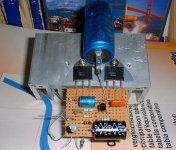
Pics will follow.
The task is pretty straightforward, and the results are excellent.
And since the circuit operates in class A, it doesn't have slew-rate issues.
In practice, R2 and R9 can be halved: the spice model I have for the LM317 reaches its current limit at only 850mA, about half the actual device. This will make the amplifier able to drive a 4 ohm load.
Pics will follow.
Attachments
Last edited:
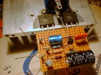
A small rectification: the circuit shown in the pictures above is slightly modified.
Here is the actual schematic.

Here is the actual schematic.
I don't think so. You'll have to try for yourself. It won't cost you a fortune thoughYou devise lots of funny amps. Will you ever tell us how they sound?
Attachments
Why not, a chip amp would make a nice, 4-quadrant PSU.Hi Elvee
Very interesting
How about a chip amp regulator ??? To feed your regulator chip amp?
Regards Ian
But the PSU would then be more expensive than the amplifier it feeds.
Why not, a chip amp would make a nice, 4-quadrant PSU.
But the PSU would then be more expensive than the amplifier it feeds.
I find the psu is offen the most expensive anyway so im guessing a four quadrant psu would cost four times as much.or is that 16???? Im not even sure what a four quadrant psu is . would it be four times as much fun to design. if so it would be worth it .
Ian
You are probably including the transformer and filter caps, which are needed anyway.I find the psu is offen the most expensive anyway
It is a supply capable not only of sourcing current, but also sinking it, and for both polarities.so im guessing a four quadrant psu would cost four times as much.or is that 16???? Im not even sure what a four quadrant psu is .
High end lab supplies have that feature, they can serve not only as conventional PSUs (with better dynamic performances), but also as electronic loads.

Can you design a capless amplifier with regulators?
Completely capless would be difficult.
This one is particularly hard: there are multiple needs of DC level shifting, and there are no good or simple alternatives.
The regulator chip amp has more or less the topology of a standard class B amplifier, and is a better candidate. But some caps would still be difficult to avoid.
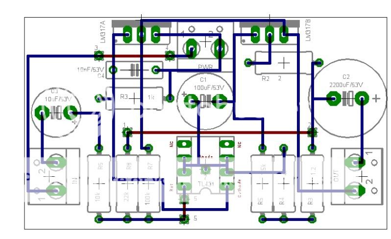
Keep playing with the design. Get the resistors up near the regulators. Try rotating all three. That big trace behind the regulators has to go. Too long. You have two sides to a board. You can use both sides for components.
Consider downloading a trial of sprint layout 6.0.
Consider downloading a trial of sprint layout 6.0.
Can you design a capless amplifier with regulators?
Yes, just one more regulator for a servo
- Home
- Amplifiers
- Chip Amps
- And now, the Regulator-Chip JLH Amp.