Kicker KX700.5 problem with Class D section

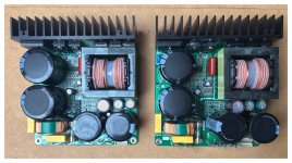
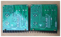
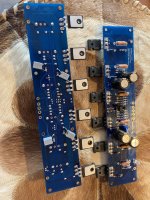
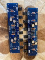
Amp came in with a blown power supply. I replaced all PS drivers, gate resistors, and about half the FETs. Good drive signal.

Amp draws excessive current but appears to power up. I removed ALL rectifiers and PS is working just fine. Then I put rectifiers in for the Class-AB side and amp works fine. Rectifiers installed in the Class-D side; and something is wrong. Amp is using IRF640/IRF9640 output transistors which are not measuring shorted. I removed the driver board with the F16/B52 ICs and the amp powers up just fine without excessive current draw.

Im not 100% positive what to look at next. Either I was going to remove the IRF640/9640 outputs to the troubleshoot the driver card (Type 1), or possibly try powering the amp through a current limiter.

Problems with Buffalo 3......

Goodmorning

Years ago i have build the Buffalo II,and a friend of mine loves it.
So we bought a Buffalo III in the marker place.....
The Buffalo II was quite easy,but the III was a differtent story for me.....🙄

The power supplies are working fine but it stays muted....
After better reading of the manual......
I came up with 2 problems:
-I think i need a Sp/dif level converter,it uses only once source.
-how can i check which firmware is on there?
With te second version all the dipswitch settings seem te be inverted.

Buffalo3.jpg

B&C ME75 vs JBL 2380A

Hi, I’m wondering if anybody has experience with both the B&C ME75 and the JBL 2380A

What I really want is a nice, non-cracked pair of 2380A to replace the cracked one in my system that I could possibly repair myself, but nobody within a few hours drive will sell me one or a pair for a reasonable price.

This has me looking at the all-aluminum alternative from B&C (a decent mfg from what I can gather) the ME75… they look very similar visually and dimensionally, however the ME75 has a wider throat opening and the curves are sharper, which makes me think the response would be more peaky, and directivity more beamy.

I will be using this horn between 700 ~ 8Khz with a 2445J driver with a radian diaphragm in a 3-way system crossing over into a Beyma CP25 or JBL 2405. I’m not so worried if the slope of the response is different since that’s something I can easily compensate for, but not peaks/internal resonances. but if it’s beamy around 8k, that’ll be a problem 🙁 Especially since i’m very content with the way the 2380A sounds in my setup

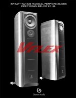
Gemme Audio's VFlex

"Getting real, strong 20 hz output from a loudspeaker is no mean feat. Going lower than that is subwoofer territory.

Gemme Audio proudly introduces the revolutionary VFlex technology, based on a unique Focused Pressure Field loading method that extends low frequency reproduction below the human hearing threshold of 20 Hertz using small drivers and enclosures. The new Vivace loudspeaker is our first model based on VFlex technology.

The Vivace are no ordinary speakers and they go LOW, real LOW, lower than 20 hz in most room conditions... That's quite amazing performance for any speaker, but their most stunning feature is not that they go that low... It"s that they can do it with a single 4" driver! Imagine what we can do with a larger driver!"

...

"Gemme Audio is aiming to offer its new VFlex line of full range loudspeakers early in 2007. After many tests and listening sessions, we've finalized the design. Utmost rigidity allied to awesome look and sound will be the hallmarks. We sincerely believe that our VFlex technology brings a revolution to the loudspeaker market. Nobody can imagine the sound of the VFlex loudspeakers when they see the small drivers. Nobody is prepared to hear full 20 hz. output from a 4" driver. But this is all real as listeners and NRC testings can testify.

Here is a comment from a reviewer waiting for a pair of Vivace : "...if you can make it a full range speaker, I think that would be incredibly awesome". Here's another comment from a web forum member : "You seem to have found the audio Holy Grail."

We'll be offering two models in the VFlex line as a start.

For the single-driver, horn sound afficionado, there will be the single-driver Vivace, offering "real" full range sound, from as low as 20 hz up the 18,000 hz, using the Fostex FE108E Sigma 4" driver in a very rigid cabinet, finished in real wood. The next model, called Tanto, will be a two-way tower, using a 6" driver paired to a Vifa ring radiator tweeter, offering bass that rivals 15" driver designs of yesteryears. Both models will offer small tower, resonant-free cabinets with sculpted front panels that are sure to offer a very high WAF!

At this moment, the look and finish are still on the drawing board but photos should be available in early January 2007.

Stay tuned to hear more about the Vflex models going where no other small driver loudspeakers have gone before."

For more look here http://66.130.192.248:9081/gemmeAudio/

What do you think? I would really like to know how the "VFlex" acutally works?

Regards
Mike

Attachments

  • vflex-speakers2.jpg
    vflex-speakers2.jpg
    62.9 KB · Views: 450

world’s smallest Christmas record—in stereo

"Nanofrazor" cuts tiny single with first 25 seconds of “Rocking Around the Christmas Tree”​

https://arstechnica.com/science/202...f-worlds-smallest-christmas-record-in-stereo/

Physicists at the Technical University of Denmark (DTU) are bringing the Christmas cheer by using a 3D nanolithography tool called the Nanofrazor to cut the smallest record ever. The tune they "recorded," in full stereo no less: the first 25 seconds of "Rocking Around the Christmas Tree." "To read the groove, you need a rather costly atomic force microscope.."

Horns + AE Dipole Build

Here is my first speaker of my own design. As a mono it’s perhaps a glorified Bluetooth speaker, but I find that I’m too restless to sit in the sweet spot long enough to justify a second unit. This opened up my budget to invest in the horns I really wanted to hear.

I had an open baffle before running audio nirvanas and eminence 15a. Fell in love with the 15a for its reproduction of the upright bass and found its polite sound great for apartment listening. I was remiss to let it go but went with the Acoustic Elegance dipole for its midrange performance figuring that the stiffer cone would also compliment my appetite for techno, rnb etc.

The horns are azurahorns 1200 and 425 crossed at 2400 and 700. Compression drivers are B&C DE250 and Radian 475pb respectively.

The aesthetic design is inspired by an old Braun radio circa Dieter Rams, the iPod mini and the pure audio project first generation open baffle speakers. I had the front panel water jet cut. The Baltic birch was cut on a friend’s CNC. I’m single but wanted this project to be aesthetically pleasing enough for when I am no longer single.

I have never heard horns before but they certainly put a smile on not only my face but friends’ and family’s as well. In some ways I miss the Eminence over the AE woofer. It was more sensitive and nimble but the AE is growing on me with its meatier presentation. If I only listened to jazz I would look at a more efficient woofer like an altec/GPA but my musical preferences lend favor to the AE.
I attenuated the horns to match the woofer using some pink noise and a db meter on my phone. Not sure how scientific that was but it got me pretty far. I felt I needed to boost everything below 200hz as high as the eq on my MiniDSP allowed and then toned everything above that slightly down further still. I do not have a measurement mic but I’m so happy with my results as they are that I probably won’t invest. Convince me otherwise?

There is a hiss coming from the horns and I’ll likely try putting line level resistors between the DSP and amps (Icepower). I have a nondescript turntable and Spotify as sources.

This board is full of inspiration! I’ve been lurking for years so thought I’d share. Feel free to share tips or comments.

Attachments

  • 6BA9D2FD-916B-4B38-9960-5FDE26AF6CA5.jpeg
    6BA9D2FD-916B-4B38-9960-5FDE26AF6CA5.jpeg
    316.3 KB · Views: 140
  • Thank You
  • Like
Reactions: DorinD and GM

Reconfigure large tower speaker as a horizontal center speaker?

Hey team - I am a newbie....have what I think is a basic speaker design question, but not sure:

I have some very large tower speakers as L/R in my home theater setup (Boston Acoustics VR3s). I have a third tower, but not able to use it as the center channel speaker vertically due to room configuration.

Can I reuse the entire speaker, components and crossover, (i.e. leave the dimensions of the speaker exactly the same), but re-build the front baffle to allow me to lay the speaker on its side, but center the midrange driver and rotate & center the tweeter? Or is this going to dramatically change the sound of the speaker?

I have strong woodworking skills and engineering background (mechanical), so the implementation is not concerning, just the design itself.

Any one with knowledge in this area, please let me know....

Thanks!

Center channel from stereo. Will this work?

Hello, Greetings!

I am just trying to develop a stereo to 5.1 conversion circuit. So far, all are working fine. For center channel from stereo, the easiest way is to combine both left and right channel with resistors and feed to op amp.

I just tried it differently, to get the center channel as shown in the image. I am using TL074 and 15V dual power supply.

So far everything works fine, but I just wanted to get expert advice, to check if this is a bad design.

CenterChannel.png


Thanks in advance!
DMA

Help for BMS 4550 FRD AND ZMA files

Hello guys, i planning to build new speakers and I can't find FRD and ZMA files for the tweeter which will use.
Can you help me with this files i try to get them from picture with Vituix, but I can't because cant find pictures with all necessary details in, or I don't understand what it's the parameters in the scale and what to fill like parameters.

https://www.lautsprechershop.de/pdf/bms/bms-4550.pdf

Greetings from Pietro!

Hi everyone and greetings from Italy!

I'm a system administrator with a great passion with music and electronics/firmware developing for ESP8266/ESP32 and Arduino based devices.
I currently own an entry level (but with great sound quality) rig based on a marantz PM6007, Project debut carbon DC Turntable, a mini PC directly connected via TOSLINK to the amplifier and a set of QAcoustics 3030i Loudspeakers + Polk MXT12 Subwoofer

I hope to share my knowledge and one of my greatest passions with you!

DIY cinema processor - requirements, preferences, opinions, ideas ?

Hello all,

I was going through the product sheets/manuals for commercial multi-way cinema processors such as the Dolby CP850, Datasat AP20, LS10 etc. Though I quickly gathered how expensive these could be for most people to use at home, I kept scrolling on just to know more. To my surprise, I happened to find that such processors (like most electronic gadgets) offered several features that did not appear very necessary/useful in a home environment that most members on the forum have.

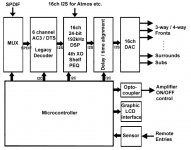
Soon, I was contemplating a basic DIY cinema processor to consolidate all the A-chain functions for a multi-way home speaker system. Based on the data from commercial units, I was able to reduce things to a list of absolutely necessary features including (but not limited to):

  • Multiple input source selection.
  • Legacy 6ch AC3/DTS decoding with provision for upto 16ch input (I2S).
  • 16-ch assignable outputs of 24-bit/192kHz audio with 32-bit processing with low latency.
  • Digital crossover upto 4th order.
  • Shelving / Parametric EQ for room/speaker compensation.
  • Time alignment.
  • Standard LCD display with simple GUI.
  • Remote control.
  • B-chain (amplifier) control.

The main aim behind starting this thread is to arrive at an affordable DIY home cinema processor that also maintains basic functionality similar to commercial units, from a home cinema point of view. I hope that the learned members on this forum could help further improve this list by sharing their thoughts, experiences, discussions, debates, opinions, ideas etc.

I already understand that there could be several combinations of DIY/ready-made hardware/software, that could be used to achieve typical function. Though I was referring mostly to a standalone processor, all opinions aimed at the welfare of the poor man hobbyist are also welcome. A block diagram for the above scheme is also attached as a starting point, apologies to those who found this post lengthy/boring.

Thanks in advance,
Happy New Year.

Attachments

  • Basic.jpg
    Basic.jpg
    48.7 KB · Views: 595
  • Like
Reactions: Dave Zan

Technics SL-P990 CD Player - Unresponsive

Hi,

Need help with this CD player. It turns on but is unresponsive in that pressing the open/close button doesn't open the tray. It's not the belt. I've had the lid off and the only thing to note is that when you press the open/close button, the laser does try to focus. I've manually opened and loaded a disc but there is little to no rotation of the disc. I also used my meter at the spindle connector and found that the +7.5V is missing but the -7.5V is present.

Does anyone know of a reason why this would happen?

I had the same model CD player a while back with the same problem but sold it on as spares/repair as I didn't have time to try to find out about repairing it. This tells me that it must be a common problem so thought I'd ask here first.

Thanks for your time.

Does anyone know what this Amplifier is - ?

Hello, I saw this Amplifier on several very recent YouTube videos - unfortunately either the person that posted the video , or YouTube has turned the comments off so there is no way to ask any questions - the Title says BA-60 Main PCB Test.... the amp is on a small PCB and it appears to just have four output devices ... it sound good as far as one can tell on YouTube videos.

here is the video -

- Login to view embedded media

Coaxial crossover conundrum

So I'm in the process of an OB "2.5" way build. Here is the parts list:

  • Amps: Tinysine TSA7800B (2.1 way, TWS, DSP, 1 per channel- currently testing single channel with a ZOUDIO 4ch)
  • Bass driver: Goldwood GW-212/4
  • Midrange: Dayton CX120-8 (4" driver)
  • Tweeter: Dayton CX120-8 (3/4" tweeter)
I am repurposing the coaxials from my PE Executive kit so it wasn't a driver I consciously chose.

Here is my concern. For the crossover frequency between the bass and midrange, I think I am OK- I will probably do something in the 300-500Hz range, well above the midrange's Fs/low frequency (~90Hz). But for the coaxial...... strangely, the low end of the tweeter (4.5kHz) is well above the beaming frequency of the midrange (~3.4kHz I think). The Fs of the tweeter (2.8kHz) is below that beaming frequency, and the tweeter does have decent SPL below its rated range but I don't want to push the crossover to say, 3k and potentially damage the driver.

So the TL;DR is, what frequency should I crossover the midrange/tweeter at? To be fair I haven't noticed anything super bizarre about the sound; I have the drivers in a test baffle now crossed over at like 150 and 5k I believe. The coax sounds a little lifeless/dull with the plain DSP crossover I have vs the passive crossover it had in the PE box so I guess I can study the original crossover to see what frequencies they chose. Here is that schematic:

1671720886800.png


What do you think? Am I overthinking this? Subjectively my only complaint is that the coax sounds a little lifeless. I will take some measurements and play with the EQ for taste I guess.

Northridge, CA (Los Angeles) - looking for new friends

I just moved to Northridge, CA and I'm looking for new friends.

-Car audio, home audio, pro audio, recording studio, diy and speaker builds, tuners, get-togethers, competitions, etc
-mountain biking, road biking, motorcycles, camping, backpacking, hiking, rock climbing
-woodworking, welding, sewing, paracord, and anything else crafty hands-on

Please send me a message or post here.

Serie passive filter EQ and phase plus impedance changes issues

Hi, Merry Christmass and last week of the year according where you 're living. (Santa, drop me your number please as I was dropped a 5 yo kid gift and eventually think there is a mistake ?!)

I would like to pad down a plateau magnitude raise on the middle of a tweeter magnitude.

A serie resistor (already existing in the filter) at the input of the passive crossover circuit is calling my noob skills for an inductor 0.5 to 1 mH parralel, to make a smooth spl notch in spite of a parallel notch with the tweeter inputs to pad down till 1 to 3 dB

I will adjudt by listening in the listening room that inductor value.

I still have to measure with better precision and better gating - 6 ms window perhaps at 1 meter then listening spot at 2.5 meters centred- the standalone tweeter response above 1500 hz. The filter being two 12 dB nodes in serie to make a sorta 24 db hybrid two nodes passive filter with a car tweeter that needs steep slope because the highish Fs for protection before the second electrical cut-off giving the near acoustical filter. I dunno if my english skills are acurate enough for the description to be understood, appoligizes if so.

I know the added parrallel coil with the serie teeter resistor will add + 90° phase change, rigth ? And a non dangerous for the amp, raise of the impedance in that area ?

Am I correct ? Why btw do we not seen that more often in tweeter filters ? Like if experienced designers prefer more global L-Pad attenuation than correcting the middle range of a tweeter non smoothness, we can by the way more often see with a resistor // caps that raise the ending level with a bigger first R attenuation ?

Any thougth on that, is it an issue to introduce a serie coil on a passive filter ? I ask cause I never seen one in my limted experience for a tweeter which has in serie caps and only // coils from 12 dB and upper slopes.

Many thanks

BSC inductor - Air core? Iron core? Lowest DCR? 3.0mH

I have a pair of Alpair 10.2 speakers in small bass-reflex cabs. I had to apply baffle step correction to get them to sound hi-fi, but I think I've arrived at a good set of values. I need to get a pair of 3.0mH or 3.3mH inductors.

The question is, for an extended-range single driver speaker for nearfield desktop listening, would I be better off using air core inductors, or iron core?

My clip-leaded lash-up uses a scrounged (and probably very cheap) pair of 2.1mH iron core inductors in series with a Dayton 1.2mH 18ga 'Perfect Lay' air core inductor to make 3.3mH. The DCR of the two is about 1.5 ohms. After much experimentation, I ended up with a 10 ohm wirewound resistor across (in parallel with) the inductors. I like the sound I'm getting.

Parts Express lists a laminated iron core 3.0H inductor with 0.36 ohm DCR that's very affordable. (US $8.59 ea)
https://www.parts-express.com/Dayton-Audio-IC183-3.0mH-18-AWG-Laminated-Iron-Core-Inductor-257-658

The 20-gauge Jantzen 3.0H air core inductor has 1.38 ohm DCR. ($14 ea)
The 18-gauge Jantzen 3.0H air core inductor has 0.99 ohm DCR. ($20 ea)

(They're out of stock of the Dayton 18ga 3.0H air core.)

I know that adding 1 ohm in series with the driver will elevate the bass response a little and make it a bit looser. Is that a good thing with a single driver? I suppose that's a taste thing, but single-driver systems do suffer from a frequency response that rises as you go up in frequency. I can live with a bit of tubby mid-bass in a high-falutin' PC speaker if the tonal balance is pleasing.

Do I want the lowest possible DCR inductor? Steel core, for best damping, tightest bass?
Or do I want air core for the most freedom from possible saturation and the most stable filtering -- and accept a slight mid-bass boost and a little worse damping?

Anybody go through this before?

ADCOM GFA 535 - Bias Adjustments

Dear All,

I currently sourced an ADCOM GFA 535 MK II and am looking at adjusting and checking the Bias to see if it is perfect.
I also read that the input jacks should be shorted when adjusting the BIAS,as per the service manual.

I am quite a noob in this topic and am quite confused with the terminology used to short the input jacks.

By shorting does it mean that the RCA plug of each channel has to be shorted, the inner ring and the outer jack of each channel the left and right. Or is it just a cable that needs to be run from Left RCA inputs to the Right RCA inputs.

I am quite a noob , in this topic and am looking forward to get inputs before i even start with it.
I will be really grateful for inputs provided.

Thanks in advance.

Full range driver Qts in open baffle application?

Im trying to consider various fullrange drivers for open baffle but would like to know what should be the Qts of the open baffle driver especially when used along with a 15 inch LF. I agree for the LF we need 0.7 Qts but for the mid to high is it mandate to have 0.7Qts? Is there anything to consider on that front for higher Qts value especially for the midrange to treble application driver?

I see many using Fe126en or even other drivers having lower Qts but said they sound good

The many parallel-TDA7293 ACE-BASS amp project

I seem to have a lot of time on my hands these days and lots of TDA7293 chip amps (more than 20pcs) staring at me from a defunkt project. As a result, I have been thinking of designing a mono amplifier PCB with up to 6-8 parallel ICs. On paper, this seems to be perfect for subwoofer duty, or even low frequencies up to about 1-2kHz where the 7293 distortion starts to rise.

What's the performance potential of the amp? If we use six 7293s and operate them from +/-40Vdc rails, by my guesstimation the amp could produce on the order of:
80W @ 8R load
160W @ 4R load
320W @ 2R load
425W @ 1.5R load
THD distortion (on paper) would be well below 0.1% (typ. below 0.05%) for all power levels up to clipping. With a 1.5R load, each device will dissipate about 15-20W with 40V rail voltages, so a good size heat sink is required (not to mention the under-power dissipation of a class AB device). The above figures are based entirely on Figure 9,10 and 13 from the datasheet for performance into 8R with +/-40Vdc rails. There are implementation specific details that influence these numbers.

I have some knowledge of the problems that one can have with a 7293 based amp. I believe that these are limited to the following two issues:
  • proper boostrapping caps must be used for the master/slaves
  • loss of negative rail causes IC to explode
That last one can be fun. One workaround is to fuse only the positive rail and ground, and leave the negative rail permanently soldered in place. Judicious choice of the bootstrapping cap for the number of ICs used makes sure that the amp operates properly. If I have missed something here, please let me know.

With that said, let's talk about the design... I'm interested in doing a "modular" design, consisting of a main board plus sets of holes that would receive "cards" that could hold up to two 7293 ICs that would be oriented perpendicular to the main board. These would be separately assembled and then soldered on to the main board. Right-angle-header type pins would connect the main board and cards (with all connections soldered). Assuming a linear power supply, I am leaning towards a separate PS/cap arrangement and local supply caps for each IC on the cards.

One other potential design aspect would be an optionally populated on-board bridging circuit. In case someone wanted higher class-AB power levels or just wants to draw current from the rails symmetrically, it would be easy to populate the bridge circuit on one board and then connect its output to the input of the other amp. To make bridging "brainless" I would use a balanced line driver IC such as DRV134 or THAT1646. This would require the addition of a line-level PS, but a shunt regulator would probably work just fine, or even something less elegant like a LM317/337 in the TO92 package plus a pre-regulator to keep the dissipation down in the regs. One question that I have is whether I should worry about DC offset for a bridged application, and whether the bridge circuitry is worth adding (e.g. maybe this would be better left for a separate board?). Please feel free to comment on this.

I'm happy to take some suggestions, start in on a design, get feedback, and then update the design. If no one has anything to add I will just post my first effort when I get something worked up. This will be a 100% DIY, license free design. I would consider posting the Gerber files when we are all done.

Let's get to it!

Reason to use 0.7 Qts in open baffle apart from frequency rolloff can we use 0.4 Qts with peak compensation ?

I see some wonderful drivers but with low qts values so now when a low qts drivers loaded in open baffle then the lower part of the spectrum there will be peak now consider we use a compensation network to reduce the peaking.
But a usual approach is any driver at qts 0.7 is suitable for open baffle or infinite baffle loading. S

So now the question is that I really want to use super high sensitivity drivers in the open baffle but all of them have Qts < 0.35 so now how far its important to have Qts 0.7 Im starting to feel that is it really required to have 0.7 or may be 0.65 ish qt or can I go with 0.3 qts with compensation network?

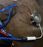
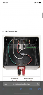
Help with impedance measurement.

Hello,
Do you think I need a better usb sound interface for measuring impedance with Arta, I am using a cheap Texas instrument PCM2902. I am not sure if the headphone input is stereo but the data sheet says so.
Or do you think there is something wrong with my connection. I am following the design of the second pic.

Attachments

  • 6E0CFF66-26C0-41A9-83D3-88DE5CAC2826.jpeg
    6E0CFF66-26C0-41A9-83D3-88DE5CAC2826.jpeg
    610.3 KB · Views: 98
  • D84CD3A0-4364-4713-A183-CD56F9923D14.png
    D84CD3A0-4364-4713-A183-CD56F9923D14.png
    345.4 KB · Views: 95
  • 680DB332-4F5A-400F-A436-C5F763D422CE.png
    680DB332-4F5A-400F-A436-C5F763D422CE.png
    142.2 KB · Views: 96

Dual mono best practices.

It seems like dual mono builds tend to double the total capacitance (and VA for that matter) rather than dividing the total power requirements equally and therefore halving the spec. for each supply. Is this a matter of "more is always better"?

For example, a build I'm considering typically employs 300va with 120,000uF total capacitance. The plan is to split the supply into dual 160va toroids and I'm having difficulty justifying doubling down on caps for a total of 240,000uF. If I reduce the total to say, 160,00uF, is this a reasonable approach?

FS: SMPS600RXE

SMPS600RxE, by Connex Electronic, is a high performance, high efficiency Resonant SMPS dedicated for High-performance Class D or Class A/B amplifiers.
The SMPS600RxE is capable to deliver 600W continuous for audio amplifiers and 760W peak power. The stock available output voltages are adjustable within 10% range.
It uses zero-voltage switching half bridge resonant topology. The main advantage is lower size and cost compared with a similar regulated SMPS and better efficiency, up to 95% compared with the regulated SMPS’s due to the fact that the transistors are soft-switched, and the current through the switches has sinusoidal shape, and there are no output inductors. The SMPS features over-current protection which limit the output current at about 120% of the maximum peak power, about 800W. The output voltage is regulated, and has very low ripple.

I have two of these for sale. Both are new and unused. They are both dual (+ and -) 72 volts power supplies.
They cost 119 Euro new. I sell them for 50 Euro each (plus shipping). PM me for shipping costs to your location.
I bought them for a project that hasn't materialized.

Attachments

  • IMG_2047.jpg
    IMG_2047.jpg
    943.1 KB · Views: 288
  • IMG_2048.jpg
    IMG_2048.jpg
    996.7 KB · Views: 243

Pass F4 diyAudio V2.0 boards – fully stuffed and working

SOLD

They say that DIY audio is a hobby and you always lose money on a hobby. I have more than that in parts, but asking price is $100. Paypal only.
  • diyAudio universal mount boards – 2010-10-23 cviller layout
  • Matched IRF sets
  • authentic Toshiba 2SJ74/2SK170 jFETs on the input, also matched
  • Nichicon Muse electrolytics bypassed by 100 nF Vishay Roederstein MKP-1837 on the bottom

You pay shipping. I pay Paypal fees. Shipping from 48118 in usa.

F4 beauty shot.JPGF4 top bottom.JPGF4 top top.JPG

Thanks for looking.

Jac

How to reattach the station search cord?

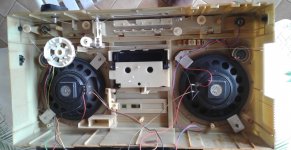
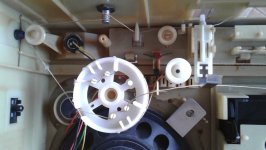
Hello, I am trying to repair a Phillips D8128 radio for my father, a few months ago the drive cord for the station search came out. Since the cord is worn in one place, thinking to replace it, he took it out of its place, he didn't go back on it and since then forgot how the cord was positioned mainly on the white wheel. I have no idea how to wrap the wire around the white wheel, would you know where I could find documentation, pictures even of another equivalent model or with the same type of wheel that could help me I would be delighted because apart from that the radio works very well. The Phillips D8120 model also seems to have the same station winding system but again it is difficult to find a doc showing how to wind.

Sincerely

Attachments

  • 1.JPG
    1.JPG
    229.8 KB · Views: 139
  • 2.JPG
    2.JPG
    143.6 KB · Views: 142

Anyone here familiar with Siglent SDS 1102CML (1000 series) ?

Im learning how to use this o-scope and it is my first one.....
Im trying to see what the waveform of an unrectified 5V AC output looks like...

I have seen videos where folks use a 2 channel scope, without any of the ground clips on the probes for safety...
I gathered from you-tube vids, instruction manual (if you can really call it that) and just poking around the menus that
I should press the math button, than the add function and finally inverting channel 2...
No luck..
Without writing a novel, nothing I have tried will give me one waveform while testing the 5v ac out

What secret buttons do the job ?

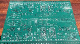
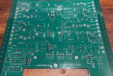
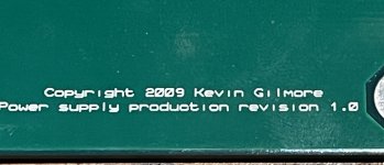
Kevin Gilmore T2, (STAX headphone amp)

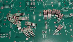
I have a complete set, amp and psu board, 2009 version 1.0. I can also supply the needed number of original Hitachi MOSFETs, the 2SJ79-2SK216.

I’m unsure of the value, so you are welcome to make me an offer.

I live in Norway and the boards are big, so the shipping will most likely be sizable.

R

Attachments

  • F57639E7-FA53-45CB-ABE8-364DEF93C3F5.jpeg
    F57639E7-FA53-45CB-ABE8-364DEF93C3F5.jpeg
    588.4 KB · Views: 312
  • 7A687297-ACC5-46AC-A71D-D8454AA6CFC8.jpeg
    7A687297-ACC5-46AC-A71D-D8454AA6CFC8.jpeg
    191.2 KB · Views: 209
  • B24D051C-699A-40EB-BDF0-1B1C3259ED95.jpeg
    B24D051C-699A-40EB-BDF0-1B1C3259ED95.jpeg
    613.3 KB · Views: 221
  • DFA93599-1182-4EED-AE35-02E4C41F0DA4.jpeg
    DFA93599-1182-4EED-AE35-02E4C41F0DA4.jpeg
    180.7 KB · Views: 224
  • DAC3C455-96AB-4C91-9C91-FAEB9115C64F.jpeg
    DAC3C455-96AB-4C91-9C91-FAEB9115C64F.jpeg
    460.9 KB · Views: 249
  • Like
Reactions: G600

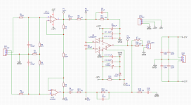
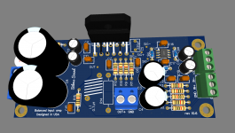
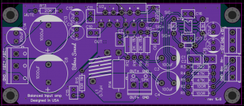
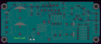
Balanced input LM3886 design and PCB layout

Here is my take on the balanced input LM3886 implementation.

Edited on 6-5-2022 with many small improvements to the schematics.
Edited on 7-16-22.
Edited on 12-23-2022

The gain for the LM3886 was eventually set to 10.

Circuit topology is an instrumentation amplifier. Balanced signal is fed into high-pass filter (100R, 100pF). We then have LM4562 opamp to provide impedance matching to the inputs of the LM3886. LM3886 chip amp is then fed two differential signals to its inverting and noninverting inputs and acts as a difference amplifier.

The gain of the LM3886 is set to 10 and is defined by the relation of the feedback resistor Rf = 20K and the input resistor Ri = 2K. Because we are using the chip amp at its minimum stable gain of 10, the stability network of Cf and Rfs is modified to omit the resistor. Otherwise, the gain of the amp is divided in two at the frequency of Cf and would equal to 5 - potentially a source of instability (in my opinion).

To ensure the HF stability two 27pF capacitors are added.

Resistors R8, R9, R10, and R11 determine CMRR or the whole circuit and should be at least 0.1% tolerance - this will allow for theoretical 66 dB CMRR. Better tolerances will allow for better CMRR, but will be limited by CMRR rating of the LM3886 itself.

lm3886-cmrr.PNG


Just a side note: 10K resistor has Johnson noise that is -112 dBU (across 20KHz range, at 20 degrees C) - according to this online calculator: https://www.daycounter.com/Calculators/Thermal-Noise-Calculator.phtml.

Feedback resistor Rf and input resistor Ri are both connected to the inverted input of the chip amp. To balance that, we need to mirror the same values for non-inverted input, except we connect resistors to the input and to the ground. This arrangement created what is known as a difference amplifier.

Since both input resistors are 2K we need a buffer to interface to the outside world and to be able to present at least 10K of impedance to connected devices.

Differential input resistance is 2 * 47K = 94K.
Common mode resistance is 47K + 2 * 2.2M = 4.447Meg.

For the balanced inputs the level of the signal is usually 4Vrms per channel. Half of that is 2. After RMS conversion 2 * √2 = 2.8284 Vpk. With the minimum gain of 10, the output voltage chip amp has to be able to handle is therefore 2.8284 Vpk * 10 = 28.284 Vpk. This is possible because LM3886 can be powered +-28V max into 4 ohm loads.

Dissipated power is another factor that determines maximum allowable power output by the LM3886:
Pd = Vcc^2 / 2* Pi^2 *Rload
For 28V supply and 4 ohms load: Pd = 784 / 19.7292 = 39.7380W
For 30V supply and 4 ohms load: Pd = 900 / 19.7292 = 45.6407W

Note that non insulated LM3886 can dissipate 40W without the fan, and insulated LM3886 can only dissipate 30W.

In our case, power supply is +-28V. We also need to subtract up to 5V for 4 ohm loads and 2.7V for 8 ohm due to chip voltage drop. 28V - 5V = 23Vpk of max output voltage swing without the distortion.

In the schematics input buffers are configured with the gain of 1+ 2 * 1K / 20K = 1 + 0.1 = 1.1. The gain of the differential stage is 10. Total gain is 10 * 1.1 = 11.
Attachments

  • sch.PNG
    sch.PNG
    32.8 KB · Views: 588
  • 3d.PNG
    3d.PNG
    68 KB · Views: 621
  • pcb-t.PNG
    pcb-t.PNG
    117.8 KB · Views: 402
  • pcb-b.PNG
    pcb-b.PNG
    98 KB · Views: 366
  • Like
Reactions: Jokerbre

Upgrades to Mission 782 crossover

I've had a pair of Mission 782 as part of my system for the past 14-15 years or so and I still really like them. They needed the mid drivers replacing when I bought them but thankfully Mission still held spares at the time.

Recently I've been thinking about upgrading the speakers to the final SE spec, which included upgraded components in the crossovers and some newer tweeters. I missed out on buying some crossovers on eBay, but the seller suggested just upgrading the original ones with better components. What are peoples thoughts about this? I know some will say it makes no difference, but looking at the current design and components there seem to be some improvements that can be made.

The original crossover looks like this:

[IMG]

Tweeter and Mid driver

[IMG]

Woofer

I've traced it all out to this circuit:

[IMG]


The crossover points are supposed to be 195Hz and 2.5kHz

It seems to me that for starters the resistors could all be changed to wire wound resistors of suitable wattage (Mills or Ohmite), and then the HF cap changed to a more modern poly film from someone like ClarityCap. The back to back electrolytics that are bypassing the woofer are an obvious thing to change too. They are a cheap way to get a bipolar capacitor, but a real no-no in some design circles - so replacing both of them with a single bipolar 470uF electrolytic seems sensible.

I guess replacing the inline MF caps would also help, three larger electrolytics and a smaller film cap. My guess is that it is a cheap way to produce 102uF with the quality of the poly cap handling the higher frequencies. The electrolytics are cheap enough to replace while I am there, and again the film caps could be changed to some nicer ones from ClarityCap.

It is interesting to note that Mission themselves used better poly caps in the SE crossover, and dispensed with the back to back capacitors configuration for the woofer. Although it seems they incorporated a higher order filter for the mid section. The polarity of the woofer seems to be swapped too, the HF cap is a higher value as well (6.8uF).

Here is a picture of the SE crossover (x2):

[IMG]


I'd be interested to hear people's thoughts before I order some parts.

Radia Pro 1.9 Build

Hello all. First post on the forum. Im hoping to get some help with a dream build for my home theater from others more knowledgable than myself. I am lucky enough to have access to 5-7 Radia Pro 1.9 75 inch planar drivers and 24 x Faital 6FE100 6.5" woofers. My plan is to build a baffle wall with angled corners behind an acoustically transparent false wall and screen, with a 75" planar and 8 x 6.5" for each of the LCR. Determining cabinet volume, amplifier power, xover settings, etc are a bit over my head at this point but I am learning. I was planning to buy a VTV 6ch amp with the Hypex NC502PM modules, but Im not 100% sure it its enough power for 8x6.5" on one channel. I should have enough DSP channels for a bi-amped LCR. The goal is to eventually add 2-4 rear channels using the 75" planars and possibly a single 10-12" woofer per speaker. Anyway, this will take some time to purchase the amplification, AT projection screen, and building materials. But I plan to share the process once the build gets started. Any advice anyone could give along the way with the details would be greatly appreciated. Thanks in advance!

Distortion question for low voltage pre stage

I saw a thread on here that was close to what I am looking for but not close enough.

Should I expect distortion in the 2% range , out of the first stage of a preamp tube with a u of 17 (12AU7)or so, given a low voltage supply like 30V at most? I know there is a ton of factors in distortion causes but should I expect to see ~ 2% at best for that low of supply?

Second question is how are most of you measuring distortion? And is anyone using LabVIEW for it? I have a Heathkit HD1 distortion meter that needs a restore but I got it working and it indicates my Sine wave generator has 1.8% THD @ 2KHz 200mv , LabVIEW shows it at 1.4% Pretty close considering the Heathkit is about 50 years old.


Alan

Did I calculate my db gain correctly?

I have 2 power amps that I would like to bi-amp in my system. They have different gains.

So I took some measurements with my scope, and here is what I measured. Both amp inputs were fed with a 1 kHz sine wave, with an 8ohm dummy load across the speaker terminal.

Amp A:
Input impedence: 15kOhms
Input voltage: 330mV
Output voltage: 4.5v

Amp B:
Input impedence: 100kOhms
Input voltage: 330mV
Output voltage: 7.2v

If I use the following formula to calculate db,
Lv = 20 log10 V0/V1 db (see attached for better rendering)

Amp A:
Gain: 22.7db

Amp B:
Gain: 26.7db

So, does this mean I need to drop 4db to get the output level from both amps to be closer together?

Does the input impedence for each amp make any difference?
The output impedence of my preamp is 600ohm.

If so, would a 3db attenuator, like the Harrison product in the attachment be close enough?

I also watched a YouTube video from PSAudio, saying a voltage divider would work. I'm making assumptions that the attenuator is just that in a consumer friendly package.

Any help would be appreciated. Thanks.
Josh

Attachments

  • FormulaLevelVolt.gif
    FormulaLevelVolt.gif
    1.7 KB · Views: 302
  • Screenshot_20210425-142419.jpg
    Screenshot_20210425-142419.jpg
    145.1 KB · Views: 306

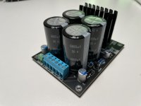
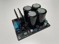
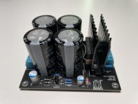
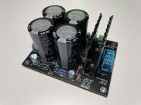
Linear Power Supply Board for Audio Amplifiers 4x6,800uF +-40V/35A and +-15V/100mA voltages

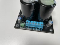
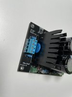
Selling linear power supply board that contains 4x6800uF 50V Nichicon Capacitors, Vishay 35A Rectifier Bridge with heatsink, LM317L / LM337L regulators for 15V out.

The board utilizes simple and straightforward design with two output voltages. PCB layout was optimized for high current flow for V+ and V- traces.

All components were sourced directly from the manufacturer or authorized distributors (TI, Mouser, Digi-Key).

Four 6,800uF Nichicon capacitors totaling in 27,200uF capacity
Up to 28V AC input voltage
Up to 40V DC output voltage
35A Vishay rectifier bridge with heatsink
16V regulated secondary voltage output based on LM317L and LM337L
Power LED connector with LED
Snubber capacitors for transformer secondary windings
Bourns 60V AC varistor for transformer secondary windings
Bleed resistor for main capacitors
Organic polymer capacitors for 16V regulated voltage output
High quality connectors accept 22 to 12 AWG wire
Board size 75mm x 100mm or 3’ x 4’

For LM3886 it is recommended to use an AC input voltage of 20V-22V to get 28V-30V out.
For TDA7293 it is recommended to use an AC input voltage of 25V to get 36V out.


I can ship anywhere in the USA.
Accept PayPal only.

Attachments

  • 6BD3AFB7-91B0-46B7-9C56-375196CAB339.jpeg
    6BD3AFB7-91B0-46B7-9C56-375196CAB339.jpeg
    266.1 KB · Views: 111
  • A3F87679-A0DE-45CF-B374-49B1F3A16A27.jpeg
    A3F87679-A0DE-45CF-B374-49B1F3A16A27.jpeg
    305.1 KB · Views: 105
  • 381C5A25-980A-4065-B301-8E9455D9BCAD.jpeg
    381C5A25-980A-4065-B301-8E9455D9BCAD.jpeg
    285.5 KB · Views: 114
  • 1ED401AE-D97D-4B3F-9017-86046C0D7876.jpeg
    1ED401AE-D97D-4B3F-9017-86046C0D7876.jpeg
    306.6 KB · Views: 114
  • DB49A235-48FA-429B-AB3A-CDDE16DC2C26.jpeg
    DB49A235-48FA-429B-AB3A-CDDE16DC2C26.jpeg
    284 KB · Views: 109
  • 649C615D-79E9-490D-A8F6-361BBF8DE350.jpeg
    649C615D-79E9-490D-A8F6-361BBF8DE350.jpeg
    276.4 KB · Views: 114

Arc Audio CXL-2500

This amp is giving trouble booting up, even on an un-restricted PS. It boot/cycles about 2 dozen times before finally powering up 'fully', but its not right none-the-less.

I followed threads here: https://www.diyaudio.com/community/threads/arc-audio-arc2500-cxl.373647

The amp will only power up every time always if I lift R110/R181/R185/R128, and D23. I replaced U19 and didn't help.

Im getting little to no -17vDC regulated. Noticed both regulators run extremely hot, LM317, 337. I replaced both and put both into an insulated sync so that they won't overheat out of the sync.

Still not getting negative regulated voltage.

Rail voltage is OK at +-68vDC

What is P1 pot in the center of the audio side? its full CCW and doesn't seem to be changing anything atm.

FS: Faital 15PR400 (2)

Barely used pair of Faital 15PR400 (<10hr of home listening test with 5W ACP mini amp). I used knob 10-32 screws that leave no trace of mounting whatsoever. For all intents and purpose they are as new. Bought them in march 2022 at parts express for $280 each. Last I looked they were ~350 each.
Sold as pair for $500 + shipping (US only). Contact me if interested.
Thanks!

I'm trying to figure out a good project amp to use with these chassis

Sometime in the dim past I bought a pair of Audimation CPA 1 amps. Never heard of them? Not surprising, no one else has either, when you google them my own question on Reddit asking if anyone had heard of them comes up first. Anyway I bought these so long ago I forgot I had them until I had to move! These are monoblocks, sturdy little buggers at about 20 lbs each.

I've been using them on my bench doing speaker measurements for the last decade or so but they're getting kind of flaky, sometimes there's a big offset on the input, other times the bias is way off, typical stuff for old amps. So thinking I could repair them I took the cover off, and luckily for me there was a schematic inside. It turns out they're a pretty basic quasi complementary design, not really worth spending much to fix.

So then I thought I could use the chassis, heat sink and transformer to make something more up to date. The biggest problem I see is that the 2 output TO-3 transistors are on opposite sides of the chassis which means I'm looking at pretty long leads for at least one of the transistors.

Anybody got any ideas on a good use for these amps? I'm open to suggestion.

Schematic.jpg
20221224_112049.jpg
20201221_145557 small.jpg

Jesus Christ Superstar, and side 4?

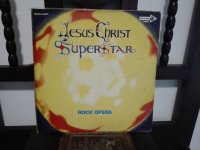
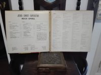
Going through my vinyl collection, I found this double LP that was a classic in my younger years. Poor Christ, every time people forget more about his sacrifice.... So I decided to listen to it one more time, but one of the sides (1 of 4) of the vinyl presents a noise that has been impossible to eliminate, it is a transversal scratch. (Yes, there are two kinds of fools, the one who lends vinyl and the one who returns it, in this case damaged) As always, the unbearable noise is in a silent passage - Murphy's Law does not fail! - . So, I wanted to listen to it on Tidal, humm, it's not there. On Spotify? humm, neither! And on You Tube? Wow, someone uploaded them and they sound great, no noise ! 😊 Eureka! But, the enthusiasm didn't last long, because I couldn't find side 4, at least in the original version, there is a Spanish version that is obviously not the same.😆 The lack of side 4 catches my attention, the guy got tired and didn't upload the last part? Is it a browser error? If someone finds it, I will be grateful if you provide the link.

Login to view embedded media

Attachments

  • IMG_20221214_180039.jpg
    IMG_20221214_180039.jpg
    214.6 KB · Views: 115
  • IMG_20221214_180054.jpg
    IMG_20221214_180054.jpg
    281.7 KB · Views: 101
  • IMG_20221214_180023.jpg
    IMG_20221214_180023.jpg
    204.5 KB · Views: 115

Trying to fix motor speed inconstancy

I have been using this Pioneer PL223 turntable for a few years, but last few months the speed has been fluctuating excessively. I have already tried re-lubricating the spindle shaft. Here is the schematic for the motor control.

PhLrCgt.png


It's a "DC Servo Control" system according the label on the turntable.

I am new to DIY audio and electronics, so although this turntable is not worth much I would like to fix it as a learning experience.

Will appreciate if anyone could point me to some information on this type of motor-control system and how it works (I noticed that unlike higher end turntables, there are no transistors or ICs involved, how is the servo control working here?) and any tips on how to go about troubleshooting this.

mic from scratch

Ive made many mics but always used speakers or actual mic elements but I always wanted to build one completely from scratch. a thick paper cone is suspended by hair bands in the center two neodymium magnets are inside a xformer with the EI core removed,the output is good only 3 db less than an sm58 but poor response, flat to 1khz then drops off very rapidly over that. the cone doesn't matter I've tried many different materials and sizes and the response is the same I'm assuming its being limited by the coil.I havent used it so im curious how it sounds.

Login to view embedded media

Tube Amp with No Spk Load???

I have a Tubes4HiFi ST120 Tube amplifier (Dynaco Copy) I built a couple years ago. I have a number sets of speakers that I like to audition from time to time. It is my understanding that you are not to disconnect speakers from a tube amplifier while it is running or for some time after you have disconnected power or damage will result?
Can I build a switch box of some type that would put 8ohm resistors on the outputs with the amplifier still on, while I switched speaker leads from one set of speakers to the other.
If "yes".....What type of switch or circuit would I build for such a device?

Thanks

HYBRID TRANS. Altec_Peerless_NL-69176-1

Hello everyone,
I have at home a pair of new Altec_Peerless_NL-69176-1 transformers. Obviously this is vintage material.
They look like input transformers with 600 or 1200 ohms on the primary and 600 ohms on the secondary.
They are very nice, big and heavy.
But then I read "HYBRID TRANS". What does that mean?
The frequency is perfect for the audio band: 20-20,000Hz.
I also don't understand the other data on the transformers.
  • Audio Level 1.5 watts
  • 100mA D.C. max Zero Unbalance
  • 500 V RMS test
Being (as they seem) signal transformers I don't think it is possible to run 500V and 100mA through them ...

Does anyone know these transformers, or even what they are used for, and where I could use them - if possible - in valve designs?
Thanks

Altec_Peerless_NL-69176-1.jpg

Help needed…Technics SA-500 phono stage

Hi, I've received excellent help here before regarding replacing caps and transistors on vintage gear and would appreciate some more. I have a Technics by Panasonic SA-500 receiver that when switched to phono makes a constant, rapid popping sound that goes away when volume is turned down and increases when volume is turned up. I assume the capacitors and maybe transistors need to be replaced on the phono circuit board. Can anyone tell me which ones and good replacements for them? Found a tech schematic on hifiengine. Just need to know which components I need to replace and where to get them.

Thanks.

Recording from a PA

I have built 2 tube monoblocks PAs.

I wanted to listen to them and sonically decide what sounds better. I have about 4 variations to try out. One is with or without GLOBAL negative feedback etc. My issue is I'm having a hard time remembering and comparing what I'mhearing. Is there a way to record the output for later playback, making it easier to decide what sounds best?

Available high efficiency tweeters in WINTER 2022/2023? (95db+ good FR to 20k)

I am looking for a current-production tweeter with high efficiency (95db+) with a frequency response flat between 5k and 20k erring on the side of "tilted up".
My budget is up to about $800 Canadian.

I am wondering if anybody can make suggestions I have not yet considered below.
Unfortunately I am one of those people who can tell when a tweeter is rolling off at 18khz... which rules out a lot of options such as the popular B&C compression drivers.

I am currently unhappy with the way my Beyma CP21/f sounds in my horn system, and I'd like to try some others. What I don't like about the CP21/f is that it seems to sound "sharp but rolled off..." despite extending to 20khz, it still lacks the shimmer I seek in most listening positions compared to other speakers i've experienced. I will be crossing over at 5.5khz

Here is the short list of the high sensitivity tweeters I have consider and their reason for not obtaining:

ModelProsCons
JBL 2405/077The "holy grail". Better response then CP21f Availability.. unknown state of diaphragms coupled with the unavailability of new diaphragms.. the sellers guarding JBL anything seem to be a rather unpleasant crowd to deal with 🙁
Selenium ST322Price Phenolic diaphragm, way too rolled off
Fountek NEOCD3.5HPrice, good response, New*Backordered/out of stock*
Beyma - TPL-150Available as New, great looking specs/responsePrice - double my budget

Soldering iron advice

Hi And thanks for reading.
I am forever having to buy new soldering irons. The ones i buy last about 2-3 months then breakdown.
I use a soldering iron for about 2 hours a day everyday, they can't seem to handle the workload. Everyone else i know has irons that have lasted for many years.
My latest is a weller 40 watt which cost me 60 quid and lasted 2 months.
What can i do, which soldering iron can i buy that can handle the work load.
Thanks

Do You Have a Solution for Bad Behavior of V-I Limiters in Bridged Amplifiers?

Hi everyone!

Back in 1980, when I was designing and building my first “serious” stereo audio power amplifier, I found the safe operating area (SOA) protection circuit to be the most challenging part. After I was finally satisfied with the V-I limiter performance in stereo mode, I then discovered that it did not perform at all well when the two channels were bridged. When limiting was triggered, the voltage across the load would “snap” to ground producing nasty sounds from the speaker (please see the attached file for a simulation demonstrating the problem). I invested more time looking for a fix, but found none that were esthetically pleasing. As I never used this mode, I eventually lost interest in pursuing it.

Jump ahead 40+ years and this issue still nags me every now and then. There must be people on this forum who have come up with a good V-I limiter solution for bridged amplifiers. I know that most of you will say “easy, don’t use V-I limiting.” This response certainly has merit and may be the best way to go, but it does not really address the question. A well-designed V-I limiter extracts the most power from the output stage while providing reliable protection.

I know the this topic was discussed in the Amplifier based on 2N3055 thread but I didn’t see a solution if it was there. My searches may have missed other discussions. Does anyone have something to contribute?

Thanks in advance!

Bruce

Attachments

LX Mini style diffusers for open baffle mid/HF

Is there any consensus about whether Linkwitz LX Mini Style absorber stuffed cylindrical diffusers mounted behind OB midranges do anything beneficial for sound? It seems they are quite well hidden in the "shadow" of the magnet structure, so I can't see much energy making it into the cylinder. I made a crude set and didn't measure much difference to frequency response. Obviously, FR is only part of the story, or maybe I didn't stuff the cylinder tightly enough. However, I haven't noticed any other designs using this configuration, have they been proven to be useless?

Attachments

  • Linkwitz-2.jpeg
    Linkwitz-2.jpeg
    81.8 KB · Views: 130
Projects by fanatics, for fanatics
Get answers and advice for everyone wanting to learn the art of audio.
Join the Community
507,837
Members
7,890,240
Messages

Filter

Forum Statistics

Threads
406,346
Messages
7,890,240
Members
507,837
Latest member
PaulPagoda