Has anyone bought TO-3 transistors lately?

I see the MJ15003/4 are back in stock at Digi-Key, albeit at ridiculous prices ($10). These were once my favorite audio transistors, and they are still capable of excellent audio today. The MJ15024/5 are slightly less expensive ($8), probably because they have slightly lower current ratings.

However, I don't see TO-3 transistors in any equipment from the past two decades. I expect that old designs are the only things keeping these transistors in production.

Given the comments about fakes, would you trust TO-3 transistors today?
Ed
  • Like
Reactions: Ite

Marantz TT42 tracking force...

Hy,
I own the mentioned TT and people online are stating that you cannot upgrade the cartridge because the tonearm had fixed tracking force...

Now this might sound as a complete nonsence as I'm new to TTs,
but there is a screw at the base of the tonearm that clearly changes the tilt of the tonearm.
I had to adjust that screw when I received the TT, because tonearm was clearly too low. It will adjust the tilt for about 1cm end to end.

Isn't tracking force dependable on the tilt?
I understand that there is no VTA adjustment and that the tilt should be in parallel with the record.

Even if this is not the solution why couldn't I remove / cut the counterweight of the tonearm and install adjustable one?
Am I missing something?

A blast from the past …Wharfedale 1cu ft cabinets

I have a pair of 60’s? Pioneer PAX 20g 15ohm Alnico drivers that have been safely packed away for years. I recently tested them and they work fine. It’s winter and Its been a while since I made anything. After a long diversion into solid state I want to build something that will work near field with flea power tubes, a darling I’m thinking of building and a 71A amp I built years ago. Room space is very tight as you can see (bedroom/office) 12x12ft and music is mostly 60’s & 70’s at moderate volumes (neighbours with kids). This will be only my second speaker build, the first being a pair of small back loaded/spiral horns using Tang Band drivers…..very happy with those, currently driven by a quad 303 ….but my 71A amp has 15 ohm outputs. I randomly thought I’d have a go at “classic” Wharfedale 1cu foot cabinets, as they will fit on my stands in the limited space available and it got me using a router to cut holes for the first time. From what I can see the original Pioneer cabinet plans for the PAX-30 a size up from mine are pretty big….I couldn’t find the plans for the 20g. In the cabinet handbook for the 1cu ft Briggs mentions building these either with a “distributed port” (slotted back) or as a straight BR with a tuned 9x1” slot port. This isn’t a vital project, just a bit of fun, but wood isn’t as cheap as it used to be And I can’t decide on…..one or many slots? Anyone got any thoughts between the straight BR or the DP?
Mike

Attachments

  • 0BD7DADC-B29B-44BD-BB02-192B3E304284.jpeg
    0BD7DADC-B29B-44BD-BB02-192B3E304284.jpeg
    454.7 KB · Views: 202
  • 20D0D006-2B82-4563-872E-5FAF588422A9.jpeg
    20D0D006-2B82-4563-872E-5FAF588422A9.jpeg
    651.9 KB · Views: 202
  • 0EDD8F5B-BF41-497F-87E4-785D423C3E3B.jpeg
    0EDD8F5B-BF41-497F-87E4-785D423C3E3B.jpeg
    426.1 KB · Views: 214
  • D1E5D3B4-1549-4528-888A-3F4F0B11185B.jpeg
    D1E5D3B4-1549-4528-888A-3F4F0B11185B.jpeg
    79.4 KB · Views: 199
  • 6752BEAE-5E82-4E81-9AA8-665615FD2A7E.jpeg
    6752BEAE-5E82-4E81-9AA8-665615FD2A7E.jpeg
    146.9 KB · Views: 192
  • Like
Reactions: hmj and GM

[DAC REVIEW] Weilang Audio DC-100 Dual AK4497 + Dual Talema PSU

Hi amigos,

Let me share my test of the Weilang Audio DC-100 DAC.
This is an awesome dual AK4497EQ Dac with a dual Talema linear PSU.

This is the top version of WA DC-100, with Nichicon caps and hi ends audiophile components. The DAC allows you to use 4 digital filters via the OLED control panel.

Setup test :

- TPA3255 Amplifier with updated OPA 1622 + Linear PSU (handmade see pictures)
- Weilang Audio DC-100 DAC
- HTC 10 Audiophile phone APTX
- Hi end floor speakers 2.5 way, 93DB @ 120W RMS handmade in France

Out of the Box :

Test with the Slow Roll digital filter + TPA3255 OPA1622 Amplifier : sounds amazing ! Via the Bluetooth APTX + HD Audio files 24 Bit (Hi res. streaming) : great dynamic, sharp and very articulated sound. Soundstage is fantastic (AK4497 help). The combo TPA3255 + AK4497 works really nice. From Jazz to Classical music files, we can ear all the details, fingers sliding on guitars, cymbals articulation, accurate voices etc...
Seems to be a great DAC but need to burn it and test with other digital filters.

I did not test via the Amanero USB port... next step )


Spec :

- Dual AK4497EQ audio Chip
- Dual Talama linear PSU
- Updates OPA 2X MUSE 02 + 2X MUSE 03
- Amanero USB Chipset
- Bluetooth APTX 5.0 CSR8675 LL HD
- DSD256/PCM384K
-Coax fiber 192 K 24BIT.
- USB 384 K 32BIT + DSD
- 2.8 MHz, 5.6 MHz, 11.2 MHz, 22.4 MHz DSD


Pictures :

IMG-20200214-232137.jpg

IMG-20200214-232156.jpg

IMG-20200214-232202.jpg

IMG-20200214-232210.jpg

IMG-20200214-232221.jpg

IMG-20200214-232225.jpg

IMG-20200214-232240.jpg

IMG-20200214-232540.jpg

IMG-20200215-150543.jpg

IMG-20200130-122852.jpg

IMG-20200130-183824.jpg

IMG-20200130-122821.jpg

IMG-20200130-211636.jpg

surveillance system camera was working and all of a sudden will not connect.

DIDSeth H.265 4CH 5MP POE Security Camera System Kit 4pcs AI IP Camera Outdoor​


is the kit that i bought, all cameras were working fine for a month then one camera took a crap, and it was a camera that was inside, never seen outisde.

i imagine some circuit might have overloaded?

i can post detailed pics but i do not have a scope or big electrical equipment, all i have is a multimeter

Tubelab SE Odd Bias Behavior

Hi All,

I have a Tubelab SE with 300B tubes that I have been happily running for a few years, but recently have been having an odd issue with holding bias. It all started when I was getting squawks in one channel which I traced down to a noisy 5842, so I replaced the two 5842s.

Since then, it's very tricky to hold the 300B bias steady at any values higher than 60ma. Once the amp has warmed up, if I set both tubes to 65ma, and check an hour later, the right one will have shot up to 85ma, the left staying around 65ma. If I turn the right down to 65ma, the left will start creeping up and the right will float down to 60ma. It seems to hold bias around 60ma in each tube, but any attempt to bring it higher then that results in the slow floating around. Even just now I set each tube to 62ma, and 5 min later the right tube is down to 61ma and the left is up to 64ms. It's not that I need the values always perfect, but my worry is that in 2 hours that left tube will have crept up to un unsafe value. Even as I have been writing this the right is down to 60ma now and the left at 65ma.

All measurements are in mV across R18 & R29, with the amp warmed up but without music playing. I have the Edcor XPWR-008 transformer, with B+ around 360-370VDC.

Anyway, I'm not sure what parts I should be checking, or any advice in troubleshooting would be much appreciated!

Preamp solid state GK 2000CPL hiss problem

hello everyone, I start by saying that I'm not an electronics expert but I really like it and I would like to give it a try to try and find a solution to the problem, practically the GK and a preamp that I connect to the marshall 9200 power amp and you hear a strong hiss that increases as the volume increases, both clean channel A and distorted channel B, both with guitar connected and not connected, I am attaching a video for now I have limited myself to trying to replace the components of the power supply stage because I thought they were the cause of the problem, the replaced components are circled in red, but the problem evidently persists not in the power supply stage. Thanks

Login to view embedded media

Attachments

  • gkgkgkg.jpg
    gkgkgkg.jpg
    31.2 KB · Views: 148

modifying Cyrus DACMaster

Hi

I've heard, that it's possible to improove some old dacs with a new clock section and/or an new dac section. A "hifi mechanic" told me so.
Is it possible for a cyrus dacmaster too?

the world wild wildlife says its using 2 x AD1862N - SM5813APT (dac parts)

Has somebody experiences?
Can somebody give me more information about the "AD1862N - SM5813APT"

thanks michael

GOLD NOTE STIBBERT Black Pearl CD-Player - Repair - Wiring Diagram

Hello,
after long time, i need again some help...

Has anybody the schematic or any experience of Gold Note Stibbert Black Pearl CD-Player?

This is a quite old CD-Player from Gold Note, using tubes in output.

The specific unit has a serious problem with the power supply as it seems that one trafo has been exploded!!
I also see that this device has been repaired again in the past, as well as heavily 'modified' (without actual reason), obviously from someone not that expertized...

Anyway, the power supply looks standard (not something special), but my problem is that due to previous repairs / modifications, i am not sure what is original and what not...

As i want to bring the player to its original condition, i would appreciate if someone could send me the wiring diagram, at least of the power supply.

Thank you in advance.

thebet

Analog Crossover Network for LX Mini complete

Hey all!

This is my first post in this forum and also my very first competed DIY audio project 🙂

I’ve been wanting to build a pair of LX Minis for years and finally pulled the trigger on everything

Looking into the crossovers for them, most people go for a Mini DSP or Mini DSP HD. After some more research, I saw that Mr Pass had designed a DIY kit for an analog version of the LX Mini crossover and not only did people say it sounds better than the Mini DSP HD, but it’s also cheaper and honestly sounded like more fun than just buying that!

While waiting for some 3D printed parts I decided to order the kit and go to town 🙂

Since the chassis and extras set has been OOS on the DIYAudio store, I had to source those on my own which honestly was enjoyable!

For this project I needed to learn how to solder, being a member at a local makerspace I was able to attend a soldering class which was great to learn the basics. So not only is this my first completed DIY audio project, it’s also my first actual soldering project and overall I had a blast putting it together!

The kit was very straightforward and very doable for a beginner in my opinion

I can’t lie the JFETs were a bit of a pain though since they need to be decently high off the board, the wires going into the centre of the RCA jacks were also a pain to actually attach with solder for some reason….

If I could change anything, I probably would have measured and lined up my rear panel better… I used a drill press to get the holes in there for the power and RCA jacks and they aren’t straight at all 😂 First time for everything! Could have also been me not lining up the drill press properly, all in all not much of an issue though as it still works and it’s just for my own personal use (and you’ll never see that side on my stand)

Sadly I can’t test it as I still haven’t actually finished the LX Minis… so I’m hoping it works right off the bat. I did test it out on my current Kef speakers and they do output audio properly (one set of RCAs being the lows and one being the highs) and the LED lights up so here’s hoping it works properly when i

Ive attached a bunch of pics of the final product + of my progress along the way below! Thanks for reading 🙂

3DEBA7A0-9025-49B2-8363-6A48F496CBE4.jpeg

324E4C47-D77A-4DD8-8F66-780E6C467BF7.jpeg

6925901B-AB9C-4C82-891B-FA5CF34BA6A9.jpeg

AFCB1499-ADE5-4A45-A7BA-B5F283D1FF0A.jpeg

9EB48744-43E9-4B54-8EE8-322B78D6900E.jpeg

E5CEE037-D78A-4451-8C22-2C34D43E6014.jpeg

330741EC-A1CC-4B76-81A4-EE68B696C394.jpeg

0A2E5207-4609-4E70-AED8-FFCAA914B83A.jpeg

46D031E9-B300-405D-83CA-9DCA9CE87734.jpeg

935086BA-DA6E-4F62-A437-04B9489A49C3.jpeg

AudioTek Q10 Mini Integrated Amp

For better and worse, I bought some bits from AudioTek in Taiwan, a vendor that had been pushing lots of stuff on eBay, and through some other channels, too. Lots of issues document with this vendor.

I bought mostly misc. components and some tubes, some of which I received, some I haven't (noted issues with this vendor and I have a couple of pending PayPal claims), but I did buy a Q10 mini stereo integrated amplifier kit (also, very inexpensive; heck, far less than I could ever buy the quality components for, which I could use, if I had to, on other projects).

The intent was to try it for 2-channel TV audio use. AudioTek seems to have disappeared - no longer listed on eBay - and I have no instruction for assembly, setup, and use of this little integrated amp. Much of it I can puzzle together, but some bits I just can't (at least not easily).

Anyone have one of these? A schematic, instructions, etc.?

TIA.

- SJ

Programming QCC3034 BT AMP circuit (first post in wrong spot)

Hi guys, its been a while since i've posted on DIY Audio and it looks different. I'm almost certain i posted in the wrong section, so below is the post i did earlier today under digital line level. Also any Admins could you please delete my original post in this original post

Hi guys, i put this question in here because of this good thread CSR8675 programming guide w. software and tons of CSR info and have in the past edited a few CSR chips, but prefer the QCC3003/3005 boards. Normally ill use my CSR\USB programmer and connect to the board with a Pogo Pin clamp and then change the name of the BT and edit the DSP\EQ settings. Recently i grabbed the QCC3034 board shown in the Aliexpress link
Screenshot 2022-12-18 190847.png


but cannot figure out what the N, P, P, V and G relates to the programmer and if i can use the Unviersal front end and APK tools like you do with the others?

Screenshot 2022-10-22 141350.png


Screenshot 2022-12-18 191318.png


I would really like some assistance if available as this amp seems to have 8watts per 4 ohm driver where my other QCC3003/5 boards only have 5 (onced boosted to 6.5v)

Crossover instead of Kube on KEF?

Hi.
A crossover instead of the Kube? Hmm.
I have a pair of KEF 107 - driven by the danish LA Audio mono tube amps. I am not quite happy with the Kube though, muds up the perspective and sound, so I mostly play without it. If you want superb clarity, pure 3d sound (but 'lack' of deep mid/bass) leave the Kube! A sofisticated bit of electronics, but it is filled with lots of ICs etc. A pitty as the 107s are very capable in the lower area.
I know very well the KEF 107 should not run without the Kube but in the long run I prefer the extreme fine sound and perspective from the pure 107s.

Has anyone tried to build or rebuild a crossover to replace the Kube? There has been a lot of discussions about these Kubes through the years. Maybe AndrewJ, former ingeneer of the Kubes, can answer whether it is adviceable or not. Lennart Andersen, former owner and guru from LA Audio, intend to build a pair of crossovers - or change the existing ones, but before that any info here would be appreciated.

By the way - look up Lennart Andersens new site: www.triodes.dk, with some exciting, new tube amps - named 'Audio Design by Lennart Andersen'. Still the champ...

IR range/wide area extender

Hi guys,

I have a setup with separate monoblocks with an IR receiver. The issue I have is that sometimes the IR command is picked up by one monobloc but not by the other, because they are not in the same space (10 ft apart). So I am looking for an IR 'blaster', something that receives my IR command and re-broadcasts it over a wider area and/or with more power.
These things are surprisingly hard to find; most 'range extenders' have small wired up re-transmitters you can place inside a cupboard to control hidden equipment, but that's NOT what Ineed.

I did find this: BestCon RM4C PRO, which seems to do what I need (plus a lot of other stuff I don't need) but I am not sure.
If you look at the right-most icon below the 1st picture here: https://www.benl.ebay.be/itm/374227163614?hash=item5721ad59de:g:zckAAOSwqUljBvWB&amdata=enc:AQAHAAAA4KJPmsWn7z4g4+0iSQEWoZLZpP21wDN1uIY7lR/foNARd/oa//tO6QXHqV6FfNDikbtzgu2BDIWQukTk7MB/nx1P2d9OnyO6rfzqiwwtwjkfiOu5U3oUwSaUIyETQHkynMAEKkNyhsPJY42/PR0LF5JGzaq9zupd32UjPpk4/WwJ0daHwl+2FsfupIN7J1Te1Z6FswL4gyUYpmWk4RjLjQEjXLWhBTlK8Yad8Vp9aPbSOIHEWu+uX1wFo9/y59iZ0i00Rk+5Nh1fVeGZym7eU7bo3Z0OnGFw1alo/cIlv9d5|tkp:BFBM6JCS7-tg
it looks like it also accepts IR commands and re-transmit it. The user guide is, as usual, not helpful at all.

Does any of you have this unit, or used it, and can educate me?

Jan

Ultimate spud amp - any ideas ?

Hi all,
I have built some nice fairly specialist amps over the last few years and I have some designs which I am really happy with and will be keeping. However they are in the 6-20W range and I recently concluded that my main speakers are only using a tiny amount of that power. I am thinking I could probably get by with between 1-3W and be more than happy.

So I am searching for a really special design for a nice Spud amp.
I have worked with the ECL82 before and have found it to be a really nice sounding tube - so its an option.
Of all the designs out there the Mighty Midget by Peter Millet strikes me as in best conformity with my design philosophy. However all my amps are now direct coupled and I would like to keep to that practice. However compactrons are a bit of a drag since they have to come from America.
I have seen a few single stage PP designs which i like the concept of, but they are not really spuds since they don't use dual triodes or pentodes.
Single stage designs are appealing.
Maybe an experiment in DHT ?

If I do this - Iwould like it to have the potential to better the amps I already have so this is something of a no holds barred though experiment.

Any ideas.

Shoog

BTM334/QCC3034 Programming

Hi All,

I'm playing with BTM334/QCC3034 module widely available on AliExpress
Particularly with this implementation but quite different BTM334 PCBA revision
The board has audio amplifier and BTM334 configured in DAC mode.
Everything works fine as expected, but I need BTM334 configured with I2S interface not DAC.
Finally the module supposed to be connected to ADAU1787 DSP codec.

I ordered BTM334 programmed with I2S interface and while waiting another 3 week for this order
started to play with existing module to see if I can configure it myself over USB.

I found a few topics on this forum explaining some steps how to do that. Many thanks to @German1212 providing valuable directions and links to tools.
Here is where I'm:
I got USB connection to the module, install the drivers, BlueSuite, unlocked access to the chip, able to dump SPI and internal Flash using NvsApp tool and following
QCC30xx USB debugging setup.pdf document from this package Thanks @ErikDIY !
I have Win11 installed on my PC and those document about driver installation listed above do not match 100% with my Qualcomm devices listed.
But NvsApp finally works and I was able to unlock chip.

I'm quite confusing about next steps.
So far, I need to reconfigure the module from DAC to I2S interface. Is it possible to do that by relatively simple ways and which tool I can use for that - QACT?
Or I need to have full ADK installed and deal with software development? What means MDE?

Can anyone have this module BTM334 PCBA revision used with I2S interface and can share *.xuv dump file "as is" to program my module?

Appreciated for the help!

TPA3118 PBTL board producing ticking sound

I've got a tpa3118 pbtl board that I want to use with MH-M18 Bluetooth module (picture in the last) and 3.5mm audio jack input both in mono mode. So I came up with this circuit.
I mixed L/R from both bluetooth and audio jack through 330E resistors and gave them to IN+ of amp selectable through a DPDT switch. (ignore the volume pot RP1 and resistor R5 since I did not connect them).
I planned on using the second pole of dpdt switch to connect audio grounds of bluetooth and audio jack separately to IN- of amp but since my bluetooth module has common ground for audio and power, and my buck convertor (for powering bluetooth) also has common ground for i/p and o/p, so I connected all grounds together and used that second pole of dpdt switch to turn the bluetooth on and off. I suspected that it connecting all grounds can cause come issue but I went on. On the output there is a woofer 4ohm/15W for testing and main power supply is 24v 2A dc smps.

schematic.PNG


On firing everything up, things went normal, music played in both BT and aux mode for sometime. After about a minute or so, music playback stopped and I got constant rhythmic ticks from speaker 1seconds apart.
Disconnected everything and just connected power and speaker to the amp (nothing on input) and got the same ticking sound.
Going through various forums, I suspect that the 3118 is going in some protection mode for some reason. Also, the board seems to follow the layout mentioned in the datasheet of tpa3118 shown below.
sch.PNG


On checking this board with a continuity tester after this accident, I found that IN-, OUT- and PWR- are all shorted which shouldn't be as per the layout above. Maybe that is why the amp is going in protection mode.

I am hoping that since it is going in protection mode, there should be a way of fixing this issue. Need help on that.
Also need a guidance on how should I connect Bluetooth having common gnd to amp and power supply keeping gnds separate.

71Q68MV8ZDL._SL1500_.jpg
Mini-360-Module-Pinout.jpg
TPA3118-Pin-Description.jpg

Audioquest RCA Interconnects - Sydney / Diamondback / Coral

I have 6 pairs of Audioquest RCA Interconnects:

1 Meter Pair of Sydney - $89 USD
0.6 Meter Pair of Sydney $79 USD


Sydney Features:
  • Direct-Silver Plated Pure "Purple-Copper" Plugs
  • Polyethylene Air-Tube Insulation
  • Carbon-Based 3-Layer Noise-Dissipation System (NDS)
  • Perfect Surface Copper +
  • Solid Core Conductors


1 Meter Pair of Diamondback (Original Version) - $69 USD
0.5 Meter Pair of Diamondback (2nd Version - Deeper Blue & Contoured RCA Plug) - $59 USD
0.5 Meter Pair of Diamondback (Original Version) - $49 USD


Diamondback Features:
Perfect Surface Copper
Double Balanced
Solid Core Conductors
Foam Polyethylene Insulation


1 Meter Pair of Coral - $49 USD

Coral Features:
Perfect Surface Copper
Solid Core Conductors
Foam Polyethylene Insulation

Take them all with FREE Insured Shipping for 349.00 USD to US / Canada

Otherwise individual purchases at asking price will include Free shipping

Will TRADE for a pair of Tang Band W8-1772 Fullrange Drivers straight-up

Attachments

  • 20221217_232844.jpg
    20221217_232844.jpg
    434.7 KB · Views: 87
  • 20221217_232850.jpg
    20221217_232850.jpg
    302.6 KB · Views: 107
  • 20221217_232857.jpg
    20221217_232857.jpg
    307.7 KB · Views: 94
  • 20221217_232907.jpg
    20221217_232907.jpg
    343.4 KB · Views: 116
  • 20221217_232913.jpg
    20221217_232913.jpg
    352.4 KB · Views: 113
  • 20221217_232926.jpg
    20221217_232926.jpg
    314.9 KB · Views: 113
  • 20221217_232938.jpg
    20221217_232938.jpg
    346.8 KB · Views: 113
  • 20221217_232944.jpg
    20221217_232944.jpg
    408.9 KB · Views: 88

Emotiva Opinions

Hello, just looking For opinions on Emotiva amplifiers. I’m looking at a BasX A2 and a BasX A2M to power some active bookshelf speakers. My luck hasn’t been so great with Emotiva, a few years ago I bought an XPA-5 and it died within a month, they sent me a new one at no cost but that one kept going into protection at least once or twice every time I used it. I am still using that it now but it’s annoying having to get up to power cycle it, and I didn’t want to pay more than $100 to have it shipped back to them. So my question is is it just a coincidence that I had two bad units in a row, or is this a known issue? The only reason I am considering Emotiva again is because they have mostly favorable reviews and good power to price performance.

I need at least 150 watts rms at 8 or 2 ohms since the woofers are dual 4 ohms. Is there anything else in the price range that has good sound quality and is reliable? I was also looking at Schiit Vidar 2 but the price will add up quick since I will need one for the woofers and one for the tweeters, and the power will be cut in half to 100 watts since the speakers are 8 ohm

Attachments

  • C07F1AB8-D99E-4302-A842-4F5A4E7835C2.jpeg
    C07F1AB8-D99E-4302-A842-4F5A4E7835C2.jpeg
    40.7 KB · Views: 124

Modern Cartridge and Stylus for Rheem Califone turntables.

I have here a mid 60's Rheem Califone Director -ll Model 15V tube turntable/PA amplifier. It's a hardy piece in excellent working order. The needle needs to be replaced. Instead, I was thinking of an upgrade to maybe an Ortofon, Audio Technica, Sumiko etc. If anyone knows about this stuff, please help me. I'd be very grateful.20220811_194838.jpg

Dirac Live 2.0 on a miniDSP. First thoughts.

I have been on a recent mission to improve the sound of a living room hifi.

I'd previously had a set of home built KEF Calinda type speakers that I'd been running via a behringer ultradrive xover and a the power amps from a NAD home cinema set up. It was loud, lively, musical but unsubtle. Terrible soundstaging and uneven bass.

Several iterations of kit later I have a pair of ATC SCM11s, an home bulit Avondale power amp and an Audiolab 8200q preamp. Still htough, the kit sounded brash on some recordings and muffled on others. Despite the huge changes to my amps and speakers, these chararteristics have been common to all setups. So, I figure, it's the room?

Fair bet it is since the setup is textbook bad. The speakers sit against the end wall but with one in a corner and the other in the middle of the wall. Both are 'too close' to the wall even for sealed cabs. However, we have the space we have and that is where they need to sit.

So, preamble over, I bought a DRC24, UMIK1 and Dirac license from miniDSP (incredible shipping BTW, 3 days from HongKong!). It's installed in the tapeloop of the preamp so can be easily switched in/out.

I've run a single set of 13 room measurementswith fairly rough/ready mic placement and tried out four target curves. The results?

Really intersting. All recordings now sound really good. Or, at least as good as you can expect a given recording to sound (rubbish in, rubbish out and all that). Certainly, all the 'cliche' test tracks sound tremendous.

No boominess in the bass, totally consistent with no nasty resonances. A bizare 'scoop' in the bass responce from 80Hz to 150Hz is gone (I've measured this on all speakers I've tried in this room/loaction). More interesting (to me at least) is that a fatiguing 'harshness' in the upper mid band is just gone. No apparent loss of clarrity, just less tiring to listen to (especially when turned up).

The surprise was the sound staging. The speakers have vanished and, for good recordings, there is far more space around the lead instruments. It feels a bit like a surround sound feature has been added but this is absolutely not a feature of DIRAC. Apparently it simply comes from improve time allignment in all the drivers.

So, I'm a fan? I think so. There are some downsides though:

1. The miniDSP itself is not really HiFi. Stick it in bypass and you switch it in/out of the signal path in your amp and you will clearly hear it's presence. Using my turntabhle as a signal source, the tone is significantly changed. It almost allmost feels a bit 'smoothed out' (bearing in mind this is bypass so straight through the ADC - DAC and out). It's not unpleasant but there is info being lost. Basically, it has a sonic signature of its own.

2. On some true golden recordings (you know, the ones you can somehow play on any system and sound good) the DIRAC Live is too much. It can somehow suck a bit of the life out of the recording. I guess this is the case where the recording is so good that it can tolerate or maybe even 'enjoy' a bit of 'room interaction' without becoming unpleasant. Miles davis 'a kind o blue' would be a good example of this.

On balance though, I'd have to say that the gains out weight the losses. Sure, it is not a purist setup, info is definitely lost. But, unless you have perfect listenting room, the sonic impact of these losses pail into insignificance compared to the sonic imperfections imparted by the room.

In short, it's a keeper for me. For the rare recording that doesn't get on with it, I can always switch the miniDSP back out. Only thing I would change is that I wish i'd known about it earlier so I could have bough a preamp with DIRAC built in (NAD C658 for example) instead of having a preamp, riaa_preamp, streamer and miniDSP.

Hope that review is useful to someone.

Cheers,

iep

Shunt Cascode Driver meets UNSET for Push-Pull

Hi,

I would like to propose you this design for a KT88 push pull amp.
The phase inverter is two Rod Coleman's Shunt Cascode Driver with a CCS on the cathodes of the two triodes, whilst the power amp is the Pmosfet cathode-driven 22% anode-grid local feedback configuration already used by TubeLab_com for his UNSET, plus 23% UL.

I attach here the schematic in jpg and LTSpice format.
I already have the output transformers, and that would be the only limit.

attachment.php


Any comment is really appreciated.

Thanks in advance,
Roberto

Attachments

I miscalculated the driver hole diameter, will it hold (photo)?

I'm making TL cabinets for Alpair 10.3. I routed holes according to the spec which says 139mm. When I tried to test fit the driver and pre drill mounting holes I realised that there is too little of meat left and I could've safely make driver holes smaller in diameter. And It's too late to redo it. I'm using 18mm MDF with 10mm cutout to fit drivers flush. Any ideas how to strengthen this area? My first idea is to put blobs of thick Poxipol epoxy under screws and redrill. Or glue pieces of 6mm MDF with the same compound.

IMG_20221216_230717.jpeg

TPS7A4700 low noise LDO regulator PCB

Hi folks,

I have busy lately and I have built some PCBs with TPS7A4700 regulator. This is a low noise regulator with output capable of 1A.

Specs
Input voltage range: 2.2V to 25V AC, 3V to 36V DC
Output voltage range: 1.4V to 20.5V DC
Output voltage noise: 4uVrms (10Hz, 100kHz)
Dropout voltage: 350mV at 1A
Output current: 1A (with sifficent heatsink)

More details
-Output voltage is configurable via solder jumpers
-Sensing pins for better performance, DUAL PCB has sensing for positive voltage only, SINGLE PCB has sensing for positive and negative voltage, if not used they can be bridged to output via solder jumpers
-DUAL PCB can be easily configured to operate in symmetrical or single voltage output (solder jumper), transformer with dual secondary windings is a must when you use symmetrical output
-SINGLE PCB can have better capacitor in sensing circuit, there is space for 5mm lead spacing capacitor (for example: Wima 1uF/63V PET)
-DUAL PCB uses bridge rectifier, SINGLE PCB uses rectifying diodes to convert AC voltage to DC voltage.
-user can fit 0805 LED diode and dedicated resistor to indicate working state of regulator

PCB size & colour
-DUAL PCB: 77mm x 37mm
-SINGLE PCB: 75mm x 26mm
-all PCBs are in black colour

What is in the offer?
TPS7A4700 single voltage output 21€

What do you get for the price
Single PCB with smt components soldered on 1pcs
SBYV27 rectifying diode 4pcs
Epcos 1uF/63V PET capacitor 1pcs
Screw PCB connector 2pcs
attached aluminum block 1pcs (works as heatsink or heatbridge)
M3 nuts 4pcs
standoffs 4pcs
Panasonic FR capacitor 1pcs

Shipping & fees, payment
Priority shipping worldwide for one PCB is 3€,for each additional PCB you'll have to add 1€. I accept only PAYPAL, fees are included in the price. You'll receive invoice for what you are buying.

Price calculation examples:
1PCS single PCB + shipping = 24€
2PCS single PCB + shipping = 46€
3PCS single PCB + shipping = 68€
...etc
Best Regards,
Ales

UPDATE: 27.2.2015 Added more components to the offer,updated price and shipping.

Attachments

  • TPS7A4700_single_schematic.JPG
    TPS7A4700_single_schematic.JPG
    92.4 KB · Views: 8,823
  • TPS7A4700_single_PCB.JPG
    TPS7A4700_single_PCB.JPG
    178.3 KB · Views: 8,517
  • TPS7A4700_dual_scheme.JPG
    TPS7A4700_dual_scheme.JPG
    122.4 KB · Views: 8,299
  • TPS7A4700_dual_PCB.JPG
    TPS7A4700_dual_PCB.JPG
    282.8 KB · Views: 8,188
  • 20141020_151823.jpg
    20141020_151823.jpg
    947.3 KB · Views: 8,033
  • 20141020_151852.jpg
    20141020_151852.jpg
    237.6 KB · Views: 2,490
  • 20141020_151900.jpg
    20141020_151900.jpg
    847.6 KB · Views: 2,049
  • 20141020_151909.jpg
    20141020_151909.jpg
    247.1 KB · Views: 1,875
  • 20141020_151919.jpg
    20141020_151919.jpg
    270.3 KB · Views: 2,838
  • 20141020_151926.jpg
    20141020_151926.jpg
    852.2 KB · Views: 2,570

Info on TAD 2402 clone needed

Dear TAD enthusiasts,
sorry in advance for the long and highly specialized post. I am in the process of building the TAD 2402 clones and I am putting together info on the xover. A couple of points that are confusing to me when looking at the french melaudia site, the hand drawn schematic by jeanphilippe and the posts by Marco Gea. I want to make sure I get the details right and I would appreciate any help.
I am afraid to post schematics here but these are readily available on the aforementioned site under the 'Filtres TAD/Kinoshita pour TSM et TSM like' thread. Of course I could post my questions there as well but I am trying to keep all my eggs in the diyaudio basket. 🙂

1) Marco Gea revises the schematic saying that L1 = 2.7mH but the hand drawn by jeanphilippe says L1 = 3.4mH.
What do you guys think?

2)I have seen people mention different kinds of HF attenuators. There are even two different schematics, one printed and the other by jeanphilippe one showing a 2 pin connection the hand drawn showing a 3 pin connection. I see mention of constant impedance attenuators and I was recommended the fostex attenuator. That's a transformer based one with primary and secondary so 4 pins. That seems different from the printed schematic that has only 1input and 1output. The transformer R100T2 based should be connected as shown here:

https://www.fostex.jp/wp/wp-content/uploads/FOSTEX_R80B_R82B_R100T2_OM_OL_A4.pdf

Does it mean that the following RLC section should be connected on the secondary downstream of the attenuator?

To keep it all in the Matsumoto family, I bought a pair of Pioneer AT 8S attenuators hopefully they are fine for the application.
Kind Regards,

Amplifying and digitalizing dynamic microphone signal using cheap boards from China.

Hi,
I want to buy boards from china for cheap, to not spend at least $50 on interface for dynamic microphone which is XM8500.
I know I need to buy AMP and ADC, but IDK what output power should the AMP have.
Here's few things I've found (I was looking for headphone and microphone AMPs, so they don't have a lot of power, but IDK how much is required for ADC, I thought is should be something around this)
AMP:

LM386 2x NE5532 NE5532 or AD828 MAX4410

ADC:

PCM1808 ADS1015 or ADS1115 ADS1115

Can any of those be reasonably paired?​

Thank you for answers in advance.

Replacing Old Signal Relays

Quick question regarding low voltage signal relays, do they degrade just sitting around new and unused? I have several NEC MR62 24V which in my case are the exact replacement model (nice for aesthetic reasons) there is a stamp on them 47/7 that makes me think 47th week of 2007 (or maybe 1997 or 1987) if that's what the numbers mean then they're at least 15ys/o.

It’s for an Onix OA21 hifi amplifier, input channel switching not speaker protection, I’ve read it’s a good idea to replace relays after about 20 years as the contacts weaken and corrode, the builder actually posted on DIYA that they should be replaced when doing a full service. Specs state contacts are gold over silver alloy and it's potted and sealed so I don't really see how they would corrode just sitting around even after many years, on the other hand the springs and coils inside might just be seized up or corroded. It's a very hard PCB to pull out IOW this is something I only want to do once while I'm recapping it.

A new set of equivalent Omrons would cost me $10 so not a big deal but I really hate to not use stuff I have on hand plus aesthetically it would look right, the NEC's are pink 🙂

DIY tonearm project going commercial

A decade ago I rescued a couple of Garrard 301s heading towards a skip. I didn't think the SME 3009 arms on them competed with my Ekos 2, and the decks sat fallow for many years. When lockdown came I decided to solve this problem.

It was my intention to try to make an arm better than my Ekos 2, and I targeted the bearing as the weakest part of that arm's design (as I suspect it may be in all gimble/ball-bearing arms), and also the most difficult to diy, so I designed an arm with a very low tech but nearly ideal new kind of bearing.

Prototype 1 sounded so much better than my Ekos that I spent many months refining the design and I applied for a patent on the novel bearing.

It has been a steady learning curve going from this...

prototype1.jpg


...to this...
4arms.jpg


...and this:
blackbird.rear.profile.jpg


Serial number 2 is now in use by an audio blogger in Canada, and this is what he has said about it:
Of the former, similarly excellent results. On my first pressing of Pentangle’s debut — a disc I have listened to a million times — I have NEVER heard Jacqui's vocals sound so clean and present. A truly moving, spine-tingling experience.
Dave Holland’s Conference of Birds is brilliant, wide, clear, with superb textures on bowed instruments, an absolute audio thrill. Low’s C’mon sounds bigger and more dramatic than ever.
I’ve noticed that my system is also sounding better at all volume levels — I don’t feel like I need to get it as loud to get into the “thrill zone.” But this is probably just another way of saying “it sounds better".
Even with much experimentation to come, I can say with total confidence that my system has clearly never sounded better. This is a stunning arm!
His deck is a Sondek and he normally uses a Tiger Paw Javelin.

Please ask if you have any questions about this project.

Web site: supatrac

How to accurately set a brick limiter, to protect drivers?

As in the title, I'm trying to figure out how to properly determine the maximum voltage / watts, or whatever that my various drivers can handle, and then understand how I would use THOSE numbers to set my limiters. (For both subs & tops.)

I of course want the option of maximum safe volume, without burning up coils.

At a minimum I'd like to understand the basic steps typically taken for this. I'm pretty sure it has to do with voltage, yes? But that's where my knowledge ends.

I do own a signal generator, a dB meter, a volt meter (Fluke 87) and some RTA software that can also somehow function as an oscilloscope, though I have no idea yet how that part actually works.
================================================


More specific helps would be even better, of course, so FWIW:

My processor is an EAW UX3600, and both tops and subs are driven by Lab Gruppen C48:4 4 channel amps.

The amps have a few different settings for maximum voltage, but no fine-tuning. The highest three choices are 100v, 118v, and 141v. With a typical input gain, this equates to about 630w, 880w, and 1200w per channel. I believe that's at 4 ohms, (the manual doesn't specifiy) as that's the maximum 1/8 power at 4 ohms. Everything I'm running now is 8 ohms per channel, so MY GUESS is that these voltages equate to about 525w, 760w, and 1,000 at 8 ohms.
These amps also have protection circuits that hard-limit the output to those voltage settings.

The processor has brick-limiters for each output. The parameter of concern here is the threshold setting, which is in dBu, and defaults to 6 dBu.
---------------------------------

Again, if anyone has the time to respond with specifics, then here are my driver specs:

TOPS: EAW KF394, currently running in full-range mode (not bi-amped) and each rated at 1100w / 8 ohms.
I'm not using that amp's outputs 3 & 4 yet, but will later when I experiment with the KF394's bi-amp mode

Two diffferent subs types, depending on the venue:

A: Bag End sealed 18's. I run four of them, and use one amp channel for each, so at 8 ohms. They are each rated at 400w / 8 ohms

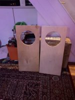
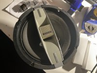
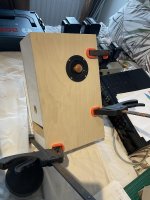
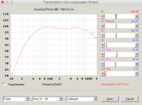
B: Two custom-made dual 12" ported boxes, each with two Eminence Kappalite 12" drivers. (Many thanks to Art W for helping me fine-tune this design.)
Again, I'm currently running each driver off of a separate amp channel, so 8 ohms each. They are each rated at 450w / 8 ohms.

And additionally - I may build a third 2X12" sub, for outdoor gigs. At that point, I'll probably change the subs' internal wiring to parallel / 4 ohms per cabinet, so I don't have to carry another amp with me. So I need to know how THAT affects maximun voltage and limiter settings as well.
=====================================================


ANY info on this at all would be massively helpful, even if just the basic concepts.

Thanks in advance, guys.

How important is it to fix things down

Hi Thanks for reading. I've built a crossover for my tweeters and have soldered the cap in series with the tweeter, then soldered the inductor across the tweeter.
Is it okay to do this, to leave the components dangling in the air like that, or is it better to fix them down in some way. I just thought it would save me money on having to buy a circuit board and this way is a lot faster, but is performance affected in any way? What is the effect.
The speaker is open-back so the components will not be buffeted by the changing air pressures.
Many thanks

3D printed waveguide - novice questions to get started

I'm slowly warming up to the idea that I may need to put my Bliesma T25Bs in waveguides. I figure I'll go with either the round 6" or 6.5" augerpro guides. They will probably be crossed over to Purifi PTT6.5Xs. I've never done any 3D printing, but I have access to some Dremel Digilab printers at work and we are encouraged to use them for personal projects. So some novice questions:
  1. What material works best for a waveguide?
  2. How do I determine how much I will need?
  3. What, if anything, will need to be done to it after it is printed to make it look good?
  4. Approximately how long will it take to print?
  5. Will I need to "check in on it" or do anything while it's printing? (I suppose, I probably will anyway)
  6. What else do I need to be aware of?
  • Like
Reactions: mikejennens

Q: restauration of '69 B&O, plinth's paint etc.

Hi friends!
I'll delve into a new little adventure: A friend of mine is collecting antique B&O gear. Among them are a wonderful "Beomaster 1200" and a "Beogram 1200". Both have a white laquered plinth, requiring a do-over...
Just doing a nice repaint-job with modern materials wouldn't be much of a problem, I probably have all the required tools (and skills), as this is part of my professional activities. But I'm inclined to go as far as possible and use the original materials and techniques, if findable and available.
Does somebody know of a good source of knowledge concerning these quite specific challenges?

thank you!

Many Used (Some New) DIY Parts

I am cleaning out my shop and here is the detailed list of parts included:

25 Used Blackgate F Series Electrolytic Caps (10 of 100uF 25V / 13 of 10uF 50V / 2 of 4.7uF 50V)

1 New Laser Assembly for California Audio Labs (Models CL-10 /Cl-15 / ICON Mk II)

4 New RFI Reducer XLR Caps (2 Male / 2 Female)

1 Used Tang Band 6" Paper Woofer Model W6-1139SI 4 ohm (Center Concave Paper Cap looks a little rough
1 - 8" Generic Polypropylene Woofer
2 Fostex / Pioneer Radial Horn Tweeter (From Audiosphere Speaker)
1 Sony 1" Sony Soft Dome Tweeter

4 Used 10000uF 63V Radial Electrolytic Caps
100+ USED Electrolytic capacitors - Various sizes and voltage ratings

8 New / Used 6 Ohm 50W Heat-Sinked Resistors with Flying Leads

1 True 75 ohm BNC to BNC coaxial Cable - 6 ft in length
2 Pairs of 18" RCA to RCA Interconnects
1 Single Female to Dual Male Splitter RCA Shielded cable

7 Used Miscellaneous Component Feet
2 Tonearm Headshells - Both Dual (?)

Take it ALL for $79 USD with Free insured Shipping to US or Canada
OR $59 without the speaker drivers

Attachments

  • 20221215_224058.jpg
    20221215_224058.jpg
    651.3 KB · Views: 171
  • 20221215_224105.jpg
    20221215_224105.jpg
    618.9 KB · Views: 166
  • 20221215_224110.jpg
    20221215_224110.jpg
    626.2 KB · Views: 155
  • 20221215_224114.jpg
    20221215_224114.jpg
    589.5 KB · Views: 156
  • 20221215_224117.jpg
    20221215_224117.jpg
    695.7 KB · Views: 169
  • 20221215_224126.jpg
    20221215_224126.jpg
    514.8 KB · Views: 162
  • 20221215_224150.jpg
    20221215_224150.jpg
    292.1 KB · Views: 164
  • 20221215_224743.jpg
    20221215_224743.jpg
    579.1 KB · Views: 176

QUAD CD66 subtle crackle on one channel

Hello,
I'm having some trouble with a quad 66 cd player. It reads instantly and sounds very nice but when it has been on for while there's a slight crackle on the right channel. It had a lot of dry solder joints so I started there (including the smd caps on the dac) and cleaned the lens but the problem was still there. I had another TDA1451A in stock so I swapped it thinking that, as it affected only one channel, it had to be the dac. The problem is still there and I probably should have done this before but I used the coax digital output on an external dac and the problem is present as well (still just on one channel). Any thoughts as to what this might be ?
Thank you!

PS : I noticed that both channels are separated inside the SAA7220 and than mixed again to be sent to the dac and the digital output, could that chip be faulty and cause this ?
  • Like
Reactions: sunil

Can you run a tube preamp without a load?

Thinking of building an active tube preamp (or buffered preamp) and would like to add a bypass switch to have the option to operate it as a passive pre as most of my sources have enough output to drive the power amp. The signal would be split after the input selector and attenuator. My question is… can I leave the preamp powered on and simply switch back and forth between the active and passive preamp? I understand tube power amps need a load or else bad things happen. Thanks!

Laptop recommendations

Hey,
I’m looking for a latop that will function as a music server. It will be also be used for internet access. I currently have a late 2012 Mac mini that’s essentially a desktop. It works fine except having a separate display is very inconvenient so portability is key. I’m unsure about budget but would like to stay under $500. Used is fine. Probably stay with a Mac but would consider a pc.
Suggestions please

EL2003CN mono input buffer replacement for Music Labs Power amp

Hi!
I came across an EL2003CN by élantec that has gone bad. It's a monolithic unity gain input buffer in a music labs ML825 power amp. It has high offset and goes crazy when heated up even just by putting my finger on it. It has a kind of strange pinout and is rated for 100mA of output with a slew rate of 1200V/µS. Does anyone know of a suitable replacement (the full datasheet is accessible on alldatasheet) ?

Drivers / parameters for ripole subs

Am trying to get enough information to understand the necessary parameters for a ripole sub driver. Optimum characteristics for different size drivers. Seems that Qt increase as driver size decrease and decrease as driver size increases. What about cone stiffness and driver mass? What about acceptable linear excerssion? Larger cones would not have to move as far but what are the practical excursion ranges.? Would like to be able to search for suitable drivers but from looking at published designs it seems that there are no set parameters with many different drivers being used.
It would seem to me that dual ripole systems are the best compromise and that larger drivers in the 15 to 18 inch range would be the most practicle way to overcome the largest and most common complaint of this design which is output. Ripoles are not the most efficient design but they would seem to be the most compact. For home theate systems where outputs above 105 db at low frequencies are desired it would appear that either multiple dual 12 inch ripoles are required (and this makes good sense in terms of driving the room) or a smaller number of 15 - 18 inch dual ripoles. I am wondering where the turning point is. Larger drivers 15 - 18 inch usually end up costing more and long throw versions are not as common as the mechanics become more involved with the higher mass structures which is part of the increase in cost. The 12 inch driver would seem to be the best all round compromise in terms of moving a lot of air and keeping the cost from getting out of hand. For a given size of motor the 12 inch represents the best balance that I can see in the market place from a cost/performance point of view.
I understand that people want/need to generate large outputs of bass in HT systems and want to get as much as they can from as few boxes as is possible but really high output at low frequencies usually gets very large or very inefficient when made smaller. Interfacing large single cabinet subs into a room does not seem to be the answer.
I am also interested to know from those with hands on experience how much of an issue ported pole noise is in ripole sub designs. Hope that we can have a polite and useful intercourse here as this topic has had some heated differences of opinion in the past. I would like to get past that to discussing the reasons behind those differing opinions. Regards Moray James.

Eminence bass guitar CB15, hopelessly "blown"?

I got an Eminence CB15 speaker in a bass guitar enclosure for free.

The Eminence rattles at around 45hz, which I notice is near it's specified resonant frequency. When I gently move the cone in and out by hand, with it out of the enclosure, I can't feel or hear any cone rub. I can't see any tears in the cone. The cone is glued solidly around the outer lip.

Recently I was able to fix an old Peavey Black Widow 15" by unbolting the magnet and rotating it 1/3, which cured the cone rub. Very gratifying!

But this one doesn't seem to have bolts. Are these things glued together?

Given the cost of recone kits now, I guess it is a paper weight if I can't get in it without cutting the cone? The free enclosure is useful for the Peavey anyway, but is there anything to be done with this speaker? It looks new and sounds great in higher frequencies.

20221206_153557.jpg

DHT filament supplies - common mode chokes (CMCs)

We discussed using CMCs with SMPS supplies in the thread on All-DHT Amplifiers, but could we continue it in more detail?

Can we also discuss using CMCs in a linear supply? Where to put them, what values, and how they help hum suppression?

Goal would be to use the supply for something like a 6B4G, 10Y, 112A stage in filament bias. Could be using Rod Coleman regs also.

Here's a simple diagram to start with that you can analyse and pull apart and suggest modifications.

Fil.Supply 6C4C-1.png

For Sale: EML 45 Solid Plate Matched Pair

Pair of 45 tubes from Emission Labs (solid plate version)

MAX 500 hours use, probably much less. Prefect condition and perfect working order. (No noise, etc.)

Original packaging (double-boxed) + certificate.

You pay shipping, whatever type you want, wherever, cost no more.

If you want, we can get the tubes tested and checked out by a 3rd party we both trust (we can discuss this). No problem.

Price is 140 euros or nearest offer.

Cheers
Deon

New SBA 8" Full Range driver

SBA is coming up with this....

8” SB20FRPC30-8 / Paper – Sbacoustics

sealed F3 is 64Hz in 30-ish litres, 38Hz in a vented 70 litres.
Very nice curve in a MLTL as well.

11mm p-to-p Xmax, 92dB sensitivity, Fs=39Hz, 50W handling power... a beast of FR driver!

I'll try to grab a pair when they come out!

Attachments

  • Screen Shot 2020-07-27 at 8.43.46 PM.png
    Screen Shot 2020-07-27 at 8.43.46 PM.png
    26.4 KB · Views: 2,296

Job lot of transformers and chokes from 2-chassis 300B amp

These 6 transformers and 6 chokes from local manufacturers were salvaged from the power supply of a 2-chassis stereo 300B amp.

Chokes are 10H 100mA (4) and 5H 150mA (2).

The transformers are designed for 240VAC mains. The 2 marked transformers are: 390.0.390/250.0.250/6.3/5 from 240V @ 0.12A, 0.1A, 1.6A and 4A respectively

I measured the 4 unmarked transformers by putting in 10VAC and measuring the secondaries and multiplying by 24.
  • The 2 medium sized transformers measured 800V (strange!), 36V (not sure what that was for) and 5V (300B heaters)
  • The 2 smaller transformers, one of which is labelled “Heaters”: 12V (for the tube rectifiers), 16.6V (which was regulated for the input/driver tubes) and 130V (presumably for the bias).
I really should have measured the voltages in-situ but the amp was old and the workmanship poor – I didn’t want to even turn it on! I was really after the Tamura output transformers which I've already advertised.

Probably not worth shipping so local pickup in Perth WA would be best.

You can have the lot for Aus$100.

Attachments

  • Transformers and chokes 1.jpg
    Transformers and chokes 1.jpg
    569.1 KB · Views: 114
  • Transformers and chokes 2.jpg
    Transformers and chokes 2.jpg
    472.1 KB · Views: 105
  • Transformers and chokes 3.jpg
    Transformers and chokes 3.jpg
    686.2 KB · Views: 109

Cyrus 2 amplifier

Hello all hope I'm placing this in the correct place but I need help!!I have a Cyrus 2 and when I turn on I get a large bong noise out of both speakers!! I have changed a few small caps but nothing! Still sounds fab but obviously not good for speakers on start up as I've had my meter on speaker terminals and dc comes through but then settles to zero after about 15 seconds.

once the amplifer has made this noise you can flick the amp off and back on and no noise but this is because I guess that it already all powered up still inside ? Please help and any suggestions welcome. I have tryed swapping the main caps and still the noise drives me crazy!!! I dont want to use it till i get ir sorted i dont want to damage my speakers!! That would just send me over the edge!😱 I use a psx with this and still does the noise when i use psx!

HHHHHHHHHHHEEEEELLLLLLLPPPPPPPPPP.

Elekit 8200 amp

I might use an Elekit TU8200R in my 4-way active speaker system to drive either the midrange driver or tweeter (or both??), with sensitivities of 91-93 dB. Given its limited frequency response for either of these drivers, power won’t be much of a problem. I currently use the Amp Camp Kit for the tweeters.

I have some questions about Elekit upgrades:

1- What advantages do the Lundahl l transformers provide over the stock Japanese ones?

2- Are there any capacitor upgrades that are worthwhile?

3- Given that this amp will not see anything low frequency, are there output tubes other than the 6L6 that would be exceptional in the midrange and higher frequencies?

Long ago, all I had were tube kit products, mostly Dynakits, and I have a need to hear that sound, again. It’s been too long without. Sorry if my questions are inane.

Thanks and Regards, Mike (michiganmike711)

12-18v 2 or 2.1 channel amplifier with Bluetooth

What are the options for a 2 or 2.1 channel amplifiers with Bluetooth and possibly line out.

Looking to make super portable and good sounding system consisting of 2 bookshelf speakers(one will have the amp bolted onto it)

It will be like a Lego transformer. Mostly use the 2 speakers attached next to each other but sometimes would want to separate them when need true stereo.

The system needs to be battery powered. 12-19v I would guess

I might add a downfiring subwoofer in a form of a base for the two speakers.

Ideally I would like 2.1 amp that can power small bookshelves + 6.5 or 8" subwoofer. If its not possible have a 2 channel system with a subwoofer out .

I've seen some options on parts-express 50+50+100w amps.
Are there any other options to consider outside parts express.

Plus need a battery. Could I use Ryobi 18v 6ah battery that comes with their tools?

Please help identify crossover input terminals

I have a pair of Audio Physic Caldera(30 years old speakers) that were passed down to me. A few years ago I tried to go active and gutted the bass crossover. Long story short, I want to put the oem bass crossover back because to me the original passive system sounded better with my 845 tube amp. It has been 5 years now, and I dont remember how the crossover were connected to the input(amplifier) terminals. The two pairs of black and red wires go to the woofers, but where is the inputs? Could you please take a look at the photos and help me? Thank you so much.

btw. This is a 3 way system. midrange and high have their own enclosure and crossover. Photos below are the bass/woofer crossover. Thx

4E2C00D3-0F5F-4B68-B7FB-98BA86717D63.jpeg
27246AEA-6FF0-489B-8369-65746D02BBBF.jpeg
FE1AA115-8443-4BAA-95F8-0C69CD0262B6.jpeg
D96E7326-CC63-4AEB-9CA6-2473BEA6E26E.jpeg

Marantz 2325 Amp Module troubleshooting

About 13 years ago, my kid had a rave party and sent square-wave like audio through my 2325. One of the right output transistors shorted and sent 60 VDC through my right JBL and blew out the woofer coil. The protection circuit - well.... didn't. The unit absolutely needs a full recap, but that is phase 2. Right now I am just trying to get the right amp module working. 13 years ago, I had ordered a bunch (a dozen each) of the output xstrs and the 747's HFE's were within a reasonable range and grouped closely. The1116A's were in two groups >1000 and <150. The also had a smaller "dome" (Cheap Chinese knockoffs?). I shelved the unit.. Now - I have replaced the TO3 2SA747A's (PNP) and 2SC1116A's (NPN) with matched pairs of these questionable (Chinese?) devices. I have replaced the three lytics and checked every smaller onboard semiconductor out of circuit. Also the power resistors are OK. I have powered the board with my current-limited bench supply that does + and - 35 VDC. Lower than the required 60 VDC but probably OK for testing. The speaker output shows 5 V DC offset which is far beyond the adjustment range, also. The voltage indication for the idle current is very high. Could these crappy output xstrs be the culprit? They test OK... Any thoughts?
Thanks, Russ KD4JO

New audio blog to share my monoblocks

Hi everyone,

All of my DIY journey was helped, if not totally so, by the great people on DIYAudio.com.

Without DIYAudio, I would not have progressed and enjoyed this hobby as much as possible. Thank you!

I would like to share a new blog that I have created which focuses on my new monoblocks and related topics. Your feedback is welcome and I will also post many of the monoblock photos on the Gallery forum within DIYAudio.com.

https://ironandglass.squarespace.com/

Hope you enjoy.

Pat

Inability to "reverse" (backfeed/step-up vs step-down) small transformer <?>

Hello - I'm a bit baffled by a no-load test on swapping the input/output on a small power transformer: 'Been doing electronics for years, but never had occasion to feed the secondary, versus primary, to get (modest plate current) HV B+ from surplus former transistor amp xformers...

In slowing ramping up the input voltage to this ~2Ampere 24vac xformer (e.g. 5:1 ratio), I was not able to get even 20vac into it - e.g. 100vac out - before it began overheating; again...no-load?!?

I regularly see 120->12->120 small ampt PS's ...but, are there some (unusual?) windings on standard power transformers that would preclude pushing them backwards - e.g. heating up on their own eddy currents? Thanks in advance for any practical experience and findings...!

Rotel RP1300, Belt drive turntable?

I've just picked up a freebie locally.
This one needs a new power cable to be legal and probably why it was free.
But it is fitted with a new OM-10 cartridge so it's probably worth fixing up. What is it that I should do; if anything?
Lubrication? If so how and with what?
Was it considered a decent TT or just something entry level, as it is pretty basic and lightweight

Pouring epoxy on toroidal

How hot is too hot to subject an output transformer to? I read that the pouring epoxy hits 200 degrees, is that too hot?

I was thinking it might be interesting to make a form and end up with a nice smooth black covering on a toroidal.

Since my outputs never get warm it generating heat in use shouldn't be a problem but the heat from the chemical reaction of the epoxy could be.

Krohn 3202 filter rehab...and cal ?

I got one of these early 1970's Krohn Hite 3202 dual Hi/Low filters - online.
The switches were stuck, but some good DuPont silicone lube freed them up. Also, I cleaned the switch contacts and sparingly applied some DeOxit, plus I installed all new electrolytic caps.
This filter now works, but I want to have a go at Calibrating it.
I have a R&S RTB2004 modern scope, and a Tek 2246 scope, and Fluke 189 handheld RMS meter.
DC offset adjust is good, at less than 0.8 milli vdc.

But the other instructions have me confused.
STEP #1 ....looks like 600hz @1v is sent to the filter input and the scope input, and the output also to the scope, in X/Y mode..... and look for an "ellipse".
All I get is what I expected.... an "in phase" 45deg straight line, and that does not change with turns of the dial.
I'm also not sure what they mean by "20 divisions" ?

20db.png


Also, with only 1.0 volt input, how does the VTVM read 20 dB ? Is the VTVM on a different scale setting ? Because with my DVM on dB mode, 1v is 0.1 dB....and.... 20dB is about 10vac.

Here is a meter scale from an older VTVM.......
(thumbnail)
s-l500.jpg

Kudelski NAGRA model "SN" (Serie Noir = Black Series) 1960s-1970s Espionage battery powered Tape Recorder

I am selling for the benefit of a former stereo salesman who has fallen on hard times (and who has trouble paying for food and fuel) an early version of the NAGRA "SN" battery-powered tape recorder, priced below market. The auction is on eBay: https://www.ebay.com/itm/334668550624

There is a YouTube of the item running: Login to view embedded media
I am hoping that by not asking cray-cray money (like everybody else does when a NAGRA SN shows up), I can help him have a nice Christmas.

john

PS: SOLD at $1,219.

Attachments

  • New NAGRA 1.JPG
    New NAGRA 1.JPG
    438.2 KB · Views: 116
Projects by fanatics, for fanatics
Get answers and advice for everyone wanting to learn the art of audio.
Join the Community
507,484
Members
7,873,832
Messages

Filter

Forum Statistics

Threads
405,560
Messages
7,873,832
Members
507,484
Latest member
Giuseppe1971