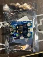
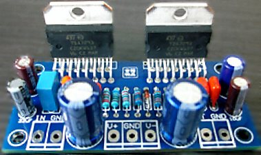
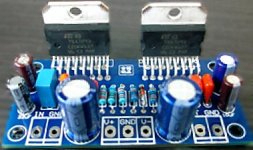
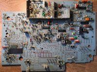
The easy little kit
This chip has Fet output built in, so it doesn't need lossy resistors at the output for paralleling.
Making two chips as easy as one.
This is documented in the
TDA7293 datasheet as a modular approach.
Notes-------------------------------------
Ebay link:
(link 1)
Two board *stereo* kit TDA7293 Parallel from HappyShop
(link 2)
Two board *stereo* kit TDA7293 Parallel from Min9988
(link 3)
One board mono TDA7293 Parallel from Happyshop
(link 4)
One board mono TDA7293 Parallel from Fly-XY
Power circuit:
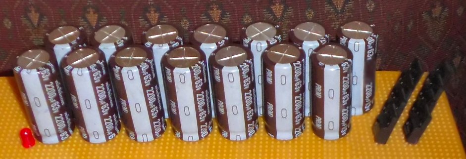
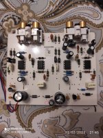
Fortunately, the kit came with 220uF power caps for the amp board, which is
perfect for clear sound and cool running of TDA7293. This setup with 220uF (or 330uF) power caps assumes that there will be larger power supply capacitance (a real power supply board).
Voltage:
If you push for quality, the Antek AN-3222 transformer is low priced, drops only 2v @13a and has ideal specs for use with TDA7293. If you push for power instead, AN-4228 is about max. However, 25+25vac dual secondaries transformer is typical and that's what I'm using.
Cap values:
I'm changing the 47uF bootstrap cap to 100uF to assist low bass (valid range 68uF to 100uF).
I will
omit the 10uF Mute cap (location is right side of the board, near speaker jack) for zero delay.
A highly effective power circuit upgrade is shown at post#30.
Instead of the 22uF FB-shunt cap (which is far too small), I'm using a 680uF 16v cap paralleled with a
0.47uF electrolytic cap for good treble. I'm also using a 1n4007 antiparallel pair as safety clipper to restrict this big cap's discharge to 0.65v. Photo is at post#29
The
105, 1uF box cap is your input cap, but there's other fun options to use, such as 4.7uF (or smaller) Elna Cerafine paralleled with a tiny polyester (to DIY your own low cost blackgate), etc. . . Try some variety and choose which you like.
Resistor values:
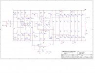
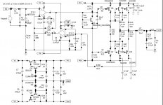
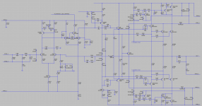
The leftmost 22K resistor is Input Load. Valid range is from 15k to 28k. A difference in value can alter the midrange loudness. If you don't need the adjustable feature shown in the schematic with 100kVR||39k, then just use a simple 22k or 25k resistor for input load.
The gain divider is the factory standard 22K/680R and although this will work, I disagree with bad performance that generic values cause. Instead, I would like to use 27K/730R for great quality. If you want quality results, the feedback resistor and the feedback-shunt resistor(s), MUST be placed underneath the board, close to the FB-Shunt cap. The feedback resistor is installed from pin14 to pin2. The feedback shunt resistor(s) are installed from pin2 to FB-shunt cap. It fits easily and shown at post#24.
The above is new text and new schematic. Previously, there had been some problem getting sufficient gain; however, a just-right gain divider setting with resistors direct (not inserted to pcb), and a power circuit update was the combination that got this little amp up to high fidelity.
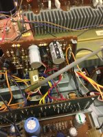
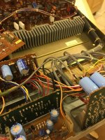
See assembly photos starting at post#24
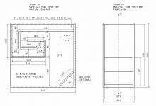
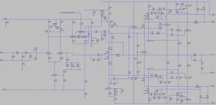
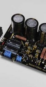
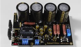
It does use a power board:
Due to the power circuit mods for power filtering at the amp board (in the photo attachments at Post#30) we didn't need a CRC type power board, so here's a simpler edition.
(5x3300u caps per rail and a pair of prefab bridge rectifiers is similar but easier.)
See also Bob's power supply
Yes, new content that uses the schematic (above) starts at post#24--previous discussion might not be applicable to the new schematic, so you will probably want to skip ahead to post 24.
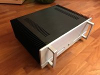


![PXL_20220430_210332374[1].jpg](/community/data/attachments/957/957815-f4fc68a6f50876af614bb3a1f2937b84.jpg?hash=9PxopvUIdq)
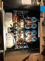
![PXL_20220430_210338499[1].jpg](/community/data/attachments/957/957816-dc09c1f76cbd40a5955fa58d06fa3585.jpg?hash=3AnB92y9QK)
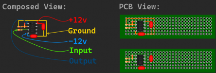
![PXL_20220430_210404260[1].jpg](/community/data/attachments/957/957817-769db54929c124f13177919d6efab17f.jpg?hash=dp21SSnBJP)