2 Layer or 4 Layer PCB design for MIC/LINE Pre-amp.

I'm design a PCB with a Mic Pre, a 3 band EQ, Balanced I/O, Headphones out, LED Vu meter and USB DAC/ADC
As the op amp uses +ve and -ve. Should I use a design a 4 Layer PCB with
- signal plane
-2 Different power planes for +ve and -ve
- GND plane
OR use a 2 Layer PCB design and just route power using traces.

(FYI my design uses - 3 NE5532 IC
- 2 TL 072
- 2 LED Led controller IC
- 1Usb DAC IC )

Magnepan 3.5 panels - Wisconsin

I have a pair of Magnepan 3.5 frames with mid/woofer panels. The crossovers and ribbons are gone. I was planning on building a 2 way speaker out of the mid/bass panels but it looks like that won't be happening anytime soon. The speakers worked well prior to the ribbons and crossovers being removed for a buddy's project. I haven't had the socks off, but I can see a bit of wire delamination through the socks.

Also included is a pair of new black socks that I purchased from Magnepan.

Asking $100 for the pair. The speakers are located in the Appleton Wisconsin area. They don't fit in my car and I don't have the packaging for them so you would have to pick them up.

Thanks for looking

Andrew

Attachments

  • 3.5 front.jpg
    3.5 front.jpg
    401.8 KB · Views: 356
  • 3.5 back.jpg
    3.5 back.jpg
    320.1 KB · Views: 343
  • Like
Reactions: Pano

For Sale Transistors Motorola MPSA43 & MPSA93

I have 500 pieces from each, they are original Motorola MPSA43 and MPSA93. I've had these for over 20 years in my stock, and no longer need them. Offers are welcome. These transistors in such a large quantity are hard to find. Prices does not include PayPal and shipping costs. Minimum order is 100pieces from each. Worldwide Buyers are welcome.. Shipping from Finland or Germany. PayPal is accepted, the buyer pays the additional PayPal fees of 5%. The shipping costs can vary depending on the country.

Attachments

  • Motorola MPSA43 MPSA93 (1).jpg
    Motorola MPSA43 MPSA93 (1).jpg
    393.7 KB · Views: 77
  • Motorola MPSA43 MPSA93 (3).jpg
    Motorola MPSA43 MPSA93 (3).jpg
    309 KB · Views: 81

For Sale Onsemi MUR3020PT Ultra Fast Rectifier Diodes

I have around 100 new Onsemi MUR3020PT – Ultra Fast Rectifier diodes, 200V, 2 X 15A, Dual Common Cathode, TO-218-3. The package has 2 diodes. Offers are welcome. The price does not include PayPal and shipping costs.

Buyers from the EU are preferred, shipping outside the EU is possible but will be expensive due to the weight. Shipping from Finland or Germany. PayPal is accepted, the buyer pays the additional PayPal fees of 5%. The shipping costs can vary depending on the country.

Attachments

  • Onsemi MUR_3020PT (1).jpg
    Onsemi MUR_3020PT (1).jpg
    296.1 KB · Views: 63
  • Onsemi MUR_3020PT (2).jpg
    Onsemi MUR_3020PT (2).jpg
    230.3 KB · Views: 73
  • Onsemi MUR_3020PT (3).jpg
    Onsemi MUR_3020PT (3).jpg
    272.2 KB · Views: 74
  • Onsemi MUR_3020PT (4).jpg
    Onsemi MUR_3020PT (4).jpg
    287.9 KB · Views: 59
  • Onsemi MUR_3020PT (5).jpg
    Onsemi MUR_3020PT (5).jpg
    280.7 KB · Views: 68

For Sale Onsemi MBR3060PT Schottky Diodes, 30A 45V,

I have around 66 new Onsemi - Schottky rectifier diodes, 60V, 30A, Dual Common Cathode, TO-247AD, 3 pins. The package has 2 diodes. Offers welcome, prices can be compared at Mouser or Digikey. Asking 2,50€/piece. The price does not include PayPal and shipping costs.

Buyers from the EU are preferred, shipping outside the EU is possible but will be expensive due to the weight. Shipping from Finland or Germany. PayPal is accepted, the buyer pays the additional PayPal fees of 5%. The shipping costs can vary depending on the country.

Attachments

  • Onsemi MBR3060PT. (1).jpg
    Onsemi MBR3060PT. (1).jpg
    274.7 KB · Views: 62
  • Onsemi MBR3060PT. (2).jpg
    Onsemi MBR3060PT. (2).jpg
    223.9 KB · Views: 68
  • Onsemi MBR3060PT. (3).jpg
    Onsemi MBR3060PT. (3).jpg
    277 KB · Views: 80

For Sale 44 Pieces MBR3045CT Schottky Diode, 30A 45V, TO-3 Package

I have 44 pieces MBR3045CT Schottky Rectifying Diodes, 30A 45V TO-3 Package. The Package has 2 Diodes. All for together for 60€.
The price does not include PayPal and shipping costs. Buyers from the EU are preferred, shipping outside the EU is possible but will be very expensive due to the weight. Shipping from Finland or Germany. PayPal is accepted, the buyer pays the additional PayPal fees of 5%. The shipping costs can vary depending on the country.

Attachments

  • MBR3045_Page_4.jpg
    MBR3045_Page_4.jpg
    307.9 KB · Views: 41
  • MBR3045_Page_5.jpg
    MBR3045_Page_5.jpg
    732.1 KB · Views: 43
  • MBR3045_Page_7.jpg
    MBR3045_Page_7.jpg
    614.3 KB · Views: 41
  • MBR3045_Page_8.jpg
    MBR3045_Page_8.jpg
    710.8 KB · Views: 40

John McKnight, a giant of magnetic recording

From Richard Hess' website, 2022 Christmas Letter (link)

John G. McKnight (“Jay”) a giant of the magnetic recording world, died on November 5, 2022 in Cupertino, California. He worked at Ampex in the 1950s and 1960s as the art and science of audio recording was being refined. In the 1970s, he started Magnetic Reference Laboratory to provide superb audio calibration tapes. In addition, he was a great help to Richard in researching recording esoterica for his papers and blog and encouraging him in his pursuit of high-quality audio tape recovery. He will be missed.
https://peoplepill.com/people/john-g-mcknight
https://en.wikipedia.org/wiki/John_G._McKnight
QUOTED from https://www.richardhess.com/family/christmas2022.pdf
  • Thank You
Reactions: GM and bOTL

Question About Using Low Leakage / Low Noise Electrolytics For Decoupling

Quick question about using low leakage / low noise e-caps like the old orange Elnas and current Nichicon KLs, I understand the benefit of using them for coupling but unsure if there’s any upside in using them for decoupling to ground, or downsides. These days the cost is a few pennies difference between LL, audio, or general purpose caps so basically I’m wondering if there are negatives, or it makes no difference. Nichicon doesn’t publish complete specs so I’ve no idea if there were trade offs to achieving low leakage like lousy ESR, resistance, or ripple values, not that high ripple is that important for coupling/decoupling. I know it would be preferable use a film cap but that is not a consideration here, I'm just curious when using low leakage e-caps for decoupling to ground, for example in a phono stage, do you get the added low noise benefit or you can actually make things worse?

3.5 way question - extending bass with active Crossover

For a 3 way speaker with sealed bass I'm thinking to extend the bass using an additional bass speaker in a wide baffle PMS-like design.
Troels G. has used a similar solution on a few occasions. For example http://www.troelsgravesen.dk/NEXT4.htm
Troels refer to it as "kind of 3.5-way".

The sealed 8" bass in the 3-way will be a magnesium W22Ex001, Deep base will be a L26ROY (likely also sealed).
The plan is to run the 3-way as full range and the L26ROY with active-lowpass filtered to pick up where the W22 role off.
For the filter I am planning to use Pass DIY 6-24 filter.

QUESTION:
What "Q" do you recommend for the 8" for a smooth transition to the lower-bass and and what filter slope would you use for the active XO?
Any feedback and suggestions welcome.

PS: Speakers and x-over kit already purchased so there most be strong arguments to change these.

For Sale Greenlee Chassis Punch Set 1/2", 3/4", 7/8", 1", 1 1/6", 1 3/8" Round + 5/8" Square

For sale is set of Greenlee Chassis Punchs 1/2", 3/4", 7/8", 1", 1 1/6", 1 3/8" Round + 5/8" Square

All of these are vintage punches and super clean with no rust. Edges are intact with no chips, dents or dings. They are sharp and work fantastic. The 1/2" is great for grommet holes and the larger ones are perfect for standard sizes of vacuum tubes.

Selling as a set. Very reasonable price

$60 + $10 shipping

PM me or email karlstolleis@yahoo.com

9.8L Markaudio CHR70 Fullrange first speaker design & build questions

Hey all! As my first ever design and build I am finally in the test box stage and got some measurements yesterday.
  • Fullrange Markaudio CHR70
  • Around 9.8L box with front facing slatted port and some fluffy stuffing and damping lining
    • Box/Port FB: 51.2 Hz
    • F3: 49 Hz
    • Port length 9"
    • Port area 5"
Did quasi anechoic measurements with far field gated/windowed above 150hz and Port with woofer combined w/baffle diffraction for near field tests, attached is the response. Few caveats: front baffle is not glued to the box as i am experimenting with stuffing/damping but firmly attached with gaskets and clamps (i know not perfect but had to compromise while testing).

* Thick Blue/yellow line is my measured speaker response
** Orange is actual Markaudio CHR70 manufacturer response
*** Black line is my enclosure simulation from VirtuixCAD

1. Is it normal for simulated low end response be this far off from actual real world measurements?
2. Not worried too much about 100hz to 500hz as I am planning on implementing baffle correction via passive or DSP
3. Any suggestions on what might be causing exaggerated spike/dip around 1500hz and what can be done?
4. Spike above 10khz is tracking manufacturers response almost one to one... do people typically leave it as it is with fullrange build?

Overall I am pretty satisfied with my first try, spent a lot of time simulating this box. Looking for suggestions for improvements and general feedback. Thank you all!

CH70 response.png


Screenshot 2023-03-11 at 4.15.46 PM.pngIMG_3265.jpegIMG_3312.jpeg

Fixing my scope

Hi all - Yesterday I pulled my old Philips PM 3240 out of its 9-year hibernation to do some fault finding on my dac.
Unfortunately the scope wouldn't turn on. I see the red light come on, the display light coming up, but then it shuts down again after 0.5sec. From thereon, it goes on/off/on/off indefinitely.

Any ideas how to fix? It seems the unit is still revivable but not sure how (cap?)

SOLITRON T0-3 transistor 0602016 8101

Greetings one and all, I am hoping someone can help me with a T0-3 Power TRANSISTOR

SOLITRON 0602016 8101 is the numbers, and a big "S" i believe is Solitron. RCA?

I been searching for a while now... Hmmmmm..... I would like SPECS and such but its from a 1978 amplifier (AUDIOMOBILE SA-1000)

Power source died this time. Uggggg This amp keeps blowing transistors?.... I am guessing thats because of the 45 year old electrolytics...

1 of 3 amps I own, this one keeps having issues. 2 times it was output transistors bad, this time its the power source. Uggggg CAPS?....

Any help will be greatly appreciated ALOHA!

Thanks!!! D

Sundown Salt 12k

This amp is using D600K and B631k as the power supply drivers for the fets .

Would the MJE171/181 and the MJE181/182 be good replacements for the drivers ?

Also every single power supply fets blew in this amp causing a lot of soot all over the board .

I know acetone and rubbing alcohol are known to clean this .

Can I also use a mild soap and water to clean the soot from the board and then make sure it’s 100% dry before replacing the parts and powering it up ?

  • Locked
Help to build two enclosures/No parameters

Hello,I recently bought two speakers for a project, and now I'm trying to figure out what volume of air they need for the enclosure and what dimensions the enclosure should have, I've never made enclosures before, but I have some understanding of the parameters.Where did I buy the speakers, the manufacturer did not publish the parameters of the speakers because they were not available, so to begin with I do not have their parameters and I have to figure out how many liters of air the speakers will need.
Speaker size: 6.5 Inch
Rated Power/Peak Power: 20W RMS/120W
Box opening: 145 - 165mm
I would be grateful if you could help me determine in the first place what volume of air they need

Differential All-Pass and Notch Filters

I'm looking for information about differential all-pass and notch filters. To me it seems like it's a very straight forward process to convert the single-ended versions to differential, but I don't want to make assumptions. The few circuits I have found were either non-nonsensical (to me at least) and others were balanced (ground referenced), not differential. I'd save myself the trouble and use single-ended circuits, however, the circuits are quite extensive. This includes an 8ᵀᴴ order active crossover(s) with over 300 parts, so along with all the other circuits, there is a significant signal path(s) length (I already have a headache thinking about all the resistors and capacitors that I'll have to match to tight tolerances).

Besides, the advantages of differential circuits such as harmonic cancellation and noise rejection make differential circuits too attractive to ignore!

Considering the topology of these filters, it appears I should be able to simply convert them to differential. The single-ended circuits have no parts going to ground (other than the op-amp's + input of course) and so even the part values would remain the same. Any experience, insight, or (helpful) comments would be great!

Thanks.​

Ocean Box -- Waves of White Noise

The Ocean Box simulates the sound of ocean waves on a beach with electronic white noise (and no crying sea gulls). A bonus feature provides pot-adjustable times for rise and fall of the waves. I mainly use headphones for white noise which is very directional. I tested a TDA7297 module with desktop speaker. It has more than enough power but 15khz is down 3db and that is not satisfactory.

Maxim DIP-8 DS1804-50 is an important component of the OB. It is a digital potentiometer with an analogue resistor array of 50k in 100 steps. The stepping is controlled by an Adafruit Metro Mini 328 which is an enhanced version of the original Arduino UNO, without the awkward footprint. Three GPIO are required for the DS1804 control and two GPIO to read the rise-time and fall-time pots. Therefore, almost any MCU could be used. For example, PIC12F675 shown here generating white noise could also be programmed for application control.

I reviewed electronic white noise in "Testing White Noise Generator Devices". I selected the PIC12F675 (from Electric Druid of Portugal) rather than abused transistors because the PIC has a deterministic signal level unlikely to blow the DS1804 input pins. I do not use opamps because gain is not needed. A buffer transistor is sufficient to protect the DS1804.

A Triad WAU12-200 powers the Ocean Box.

Attachments

  • Box1.png
    Box1.png
    16.2 KB · Views: 96

For Sale Hammond 1628 SEA Output Transformers and Chassis Covers + TubeLab SEII Parts/Board For Sale

So a few years back I built a TubeLab SE II (Single Ended 300B) Amp and its amazing. So amazing I was going to build a second one but life got in the way and I have decided to sell off the whole kit. Would be a great starting point for someone wanting to build a TubeLab SE II amp. Included are

Hammond 1628 SEA Single Ended Output Transformers - these sound amazing and weigh a TON
Edcor CXC125-10H-200mA choke
Edcor XPR178-120 Power Transformer
Steel Chassis Covers for all four - NEW, Matches Hammond Chassis paint almost perfectly. See pics for my finished amp to see what you get
TubeLab SE II Board Partially Assembled - come with gold plated ceramic sockets, Oversized capacitors and Vishay Mil-Spec low tolerance resistors installed. Audio Cap Theta Capacitors also installed. Have all the power ICs and oversize heatsinks not installed. Will include parts installation checklist that shows current state of board and notes on build/checkout
A fair amount of 18 and 16 gauge mil-std wire in various colors. Some are already twisted pairs and colors should match up with the TubeLab diagrams on website - plus new colors
A roll of 18 gauge mil-std shielded wire - I use this for input signals with grounded shield
A few gold plated connectors that I used for outputs

The pictures of completed amp are for example - not selling completed!!!

Transformers are heavy but shipping should be reasonable - $35 range with UPS

Hammond Transformers alone are $190/ea at Mouser

This is an all or nothing deal - ASKING $225+shipping

PM me or email to karlstolleis@yahoo.com

Attachments

  • IMG_2122.JPG
    IMG_2122.JPG
    351.5 KB · Views: 164
  • IMG_2123.JPG
    IMG_2123.JPG
    285 KB · Views: 119
  • IMG_2124.JPG
    IMG_2124.JPG
    302.2 KB · Views: 118
  • IMG_2125.JPG
    IMG_2125.JPG
    603.3 KB · Views: 126
  • IMG_2126.JPG
    IMG_2126.JPG
    402.8 KB · Views: 151
  • IMG_2127.JPG
    IMG_2127.JPG
    426.1 KB · Views: 122
  • IMG_2128.JPG
    IMG_2128.JPG
    460.4 KB · Views: 163
  • IMG_2129.JPG
    IMG_2129.JPG
    395.9 KB · Views: 143
  • IMG_2130.JPG
    IMG_2130.JPG
    556.4 KB · Views: 130
  • IMG_2131.JPG
    IMG_2131.JPG
    457.6 KB · Views: 130
  • IMG_2132.JPG
    IMG_2132.JPG
    429.3 KB · Views: 142
  • IMG_2133.JPG
    IMG_2133.JPG
    427.5 KB · Views: 138
  • IMG_2134.JPG
    IMG_2134.JPG
    557.5 KB · Views: 150
  • IMG_2135.JPG
    IMG_2135.JPG
    695.5 KB · Views: 136
  • IMG_2136.JPG
    IMG_2136.JPG
    630.1 KB · Views: 133
  • IMG_2137.JPG
    IMG_2137.JPG
    620 KB · Views: 125
  • IMG_2138.JPG
    IMG_2138.JPG
    665.2 KB · Views: 115
  • IMG_2139.JPG
    IMG_2139.JPG
    688.3 KB · Views: 121
  • IMG_2140.JPG
    IMG_2140.JPG
    370.2 KB · Views: 135
  • Like
Reactions: manniraj

A new HF unit, very nice looking.

A parcel arrived the other day, a box containing two smaller boxes.

371a_zps9cba82c2.jpg


What might be inside the small boxes?

371b_zpsd92e8864.jpg


Ah! A nice looking bullet tweeter!

This one a bit special, ringradiator, or annular ring, wichever You prefer, membrane, the same as in the HF104, my favourite compression driver, compared to the traditional bullet units it has quite a large bandwith, usable from 2,5k.

Buildquality, as usual from Faital, is ridicously good.

371c_zps2602e68b.jpg


Measurments from manufacturer are very good, will do my own to compare.

5937-4-fd371spl1_zps05aaede4.gif


Ingvar

My Bias in LTspice don't work

Hello I am trying to simulate a bias circuit in LTspice, but it does not seem to work.
The potentiometer don't have any effect on the negative voltage.

Here is the asc. Can you help me simulate the transformer AC and rectification, the pot that set the negative bias, don't seem to have any effect.
I used 2 resistors as a pot.

Thank you.

Attachments

is there interest in a new TubeTester?

Dear all,

would there be interest in a (digital) Tube-Tester as a commercial product? To my knowledge, there are now only historical tube testers sold, and a few kits for tube tester. I know this overview of existing (and old) Tube Testers: http://www.jacmusic.com/Tube-testers/Digital-Testers-Compare/FRAMES/COMPARE-INDEX.htm

I am thinking of making a regular product, with FCC test, of such a device. Depend on interest, there could be additional to the test functionality, also a "Tube regenerating function". I have a book from 1943, where 2 German engineers describe the regeneration of death tubes, and there is a small community around the globe what use that technique with some success.

The sales price would be in the range of 500 USD for a simple device, an 1000 USD for the Delux version. What do you think, would there be a market for this? If there is enough interest, I could do a kickstarter.com campaign.

Infinity 8 Kappa Rescue Project

I just picked up a pair of 8 Kappa speakers from my local consignment shop for $50.00. Cabinets and grilles in great shape.

All voice coils check good, but the Polydome mids need need new domes and the 12" woofers are non standard cheepos. All tweeters and mids are very clean.

Anyone know where I can source suitable replacement domes(plastic only)? I fancy my hand at trying to rebuild them before replacing them with non-standard drivers.
I thought maybe a voice coil dust cap if nothing else, might work.

Cheers
Peter

Very annoying hiss with a Chinese SOUNDIGITAL copy!

Hi everyone.
I ask for your help to understand where the problem lies and possibly how to try to solve it once and for all.

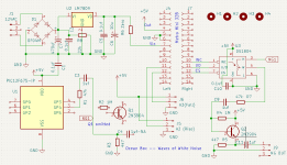
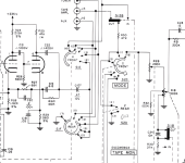
I'm dealing with the classic, usual Fullbridge amplifier Chinese copy of the Brazilian sounddigital.
It seems that there are various Chinese brands that copy them.
One in particular is really excellent and builds amplifiers for a handful of brands here in Italy, while others appear to be very poor, as they have (factory new) enormous and very annoying background hiss if used on the front speakers.

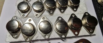
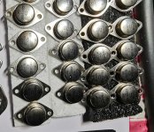
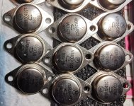
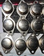
I've compared all 3 models (sounddigital, good Chinese brand and bad Chinese brand) and they really look the same, except for a few things, but they basically work the same.

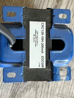
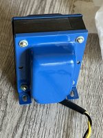
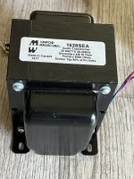
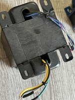
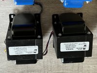
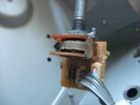
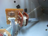
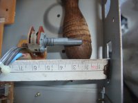
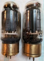
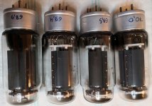
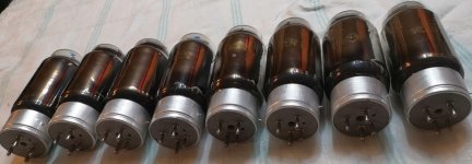
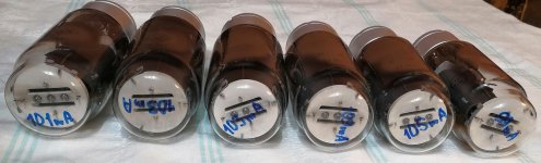
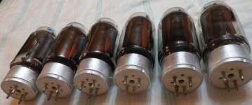
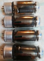
The thing that immediately struck me are the output inductors, which are different between the 2 Chinese brands.

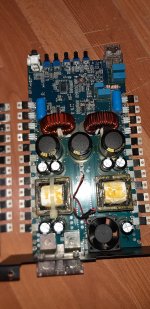
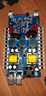
I'll try to attach 2 images of a good Chinese 5000 and a poor Chinese 5000, to show the "differences" that I struggle to find.
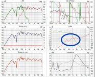
The tests that have been done on the bad Chinese amplifier:
1) the background hiss seems to decrease significantly if the supply voltage is </=10v, so I thought that by regulating the feedback circuit to have a coincident rail even at 14.8v I would have solved the problem, but not it solves.

2) I thought of a preamplifier problem, but separating it from the rest of the amplifier by removing the "DC decoupling cap" I correctly separated the preamplifier from the amplifier, but the hiss remains.

3) I tried to level and strengthen the power supply of the entire preamplification, but the hiss remains.

4) I tried to somehow modify the values of the filter capacitors on the amplification stage, but the problem remains, indeed it could get worse (I did this test, because I noticed that the values of the Chinese amplifier are different from those of the sounddigital original)

5) I tried to install additional 6.8uf 400V ceramic capacitors, as close as possible on the pins of the output mosfets, but the problem is not solved.

After doing all these USELESS tests, I'm seriously starting to think that the fault lies with the output inductors, which are literally terrible.
But I ask you, maybe someone has already understood something, and wants to help me.

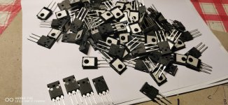
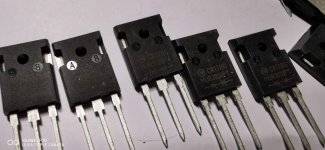
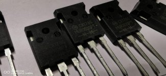
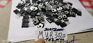
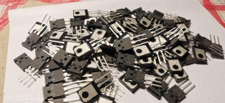
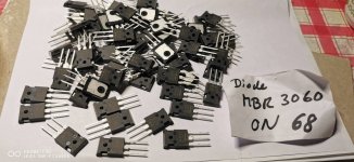
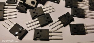
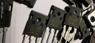
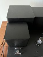
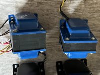
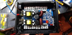
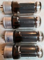
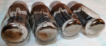
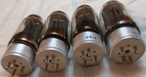
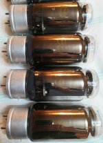
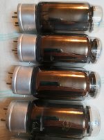
As you can see from the photos, although all 3 are 5000w, the sounddigital and the good chinese copy, use only one power terminal block and a single output terminal block, also, the diodes are to220 format, while in the bad chinese copy, we have even 2 power terminal blocks, a double output terminal block and the diodes are in TO247 format.

The latter would be very favorable factors to a bad Chinese copy, if it weren't for the fact that, in practice, the amplifier is worthless.
A thousand thanks.

Attachments

  • original SD 5000.jpg
    original SD 5000.jpg
    399 KB · Views: 209
  • GOOD CHINESE COPY.jpg
    GOOD CHINESE COPY.jpg
    449.2 KB · Views: 202
  • BAD CHINESE COPY.jpg
    BAD CHINESE COPY.jpg
    374.8 KB · Views: 198

Jantzen HES-8008 x1 f/s Uk

I bid on a pair of these recently and unfortunately managed to win 1 and the seller / other buyer wasn't interested in either buying this other one or selling me the other. Why list them separately I'll never know. What a shame to split the pair.
So I have 1 to sell. Pretty useless I admit .
Seems in very good order apart from a slight mark on the cone. Purely cosmetic I'm sure.
Will post anywhere at cost.
£75

Attachments

  • IMG20230312164457.jpg
    IMG20230312164457.jpg
    391 KB · Views: 78
  • IMG20230312164505.jpg
    IMG20230312164505.jpg
    352 KB · Views: 82
  • IMG20230312164513.jpg
    IMG20230312164513.jpg
    402.9 KB · Views: 83
  • IMG20230312164533.jpg
    IMG20230312164533.jpg
    547.5 KB · Views: 82
  • IMG20230312164605.jpg
    IMG20230312164605.jpg
    280.5 KB · Views: 84
  • IMG20230312164623.jpg
    IMG20230312164623.jpg
    256.3 KB · Views: 88
  • IMG20230312164701.jpg
    IMG20230312164701.jpg
    300.8 KB · Views: 79

ALPS (RK163 Series) with Loudness TAP (4 Terminals) 40mm shaft length and single D-Shaft - Custom Made or not ?

ALPS Stereo Potentiometer for Volume Control (RK163 Series) with Loudness TAP (4 Terminals) 40mm shaft length, single D-Shaft (Flat, not slotted, not knurled) - standard part or custom made ?

The attached PDF do mentioned the meaning of the individual digits behind the naming "RK163".
According this the order code of wanted version is RK163 F40 C0
This don't correspondent with this sheet:
https://tech.alpsalpine.com/e/products/category/potentiometer/sub/01/series/rk163/
go to
https://tech.alpsalpine.com/e/products/detail/RK16312A0B85/

The integrated amplifier Harman HK610 use a 4-tap volume control from the Alps RK163-Series (30KBX2).
An attached picture - found on the web`under
https://imall.com/product/1pcs-lot-...ts/aliexpress.com/32788254523/568-1853866/en?
- show exact this potentiometer. Another version too, but with additional motor - found on the web under
https://de.aliexpress.com/item/32851918753.html
Obviously identical potentiometer is implemented in the motorized version from this company:
https://vicko.ecer.com/products.html
go to the attached image No 2-5

Harman's order code is "5113-S20043003" - go to service manual under
https://web.archive.org/web/20130323122720/https://diagramas.diagramasde.com/audio/HK610 sm.pdf

Where I can order a potentiometer in this 4-tap outline (30KBx2 or maybe 50KBx2 or 100KBx2) ?

The good known blue Alps RK27112 was offer in a 4 tap version for loudness - go to
https://www.aliexpress.com/item/32860672317.html?gatewayAdapt=glo2deu
and
https://www.iwistao.com/en-de/produ...japan-alps27-type-100k-hifi-diy-free-shipping
and
https://www.diyaudio.com/community/threads/alps-rk27-50k-with-4-pins-in-row.391119/
unfortunately not with the right shaft length and D-shaft (flat shaft). Another disadvantage is the need for more space.

P.S.: Luxman's L190 and L210 use also the outline from image No 1 with additional loudness tap for it's volume control, but 100KBX2 instead 30KBX2 resistance (Stock-No 18T56665F01) - so I guess, no custom made version.

Attachments

  • 1pcs-lot-Japan-made-dual-potentiometer-ALPS-16-potentiometer-with-a-tap-30K-special-X230F.jpg
    1pcs-lot-Japan-made-dual-potentiometer-ALPS-16-potentiometer-with-a-tap-30K-special-X230F.jpg
    83 KB · Views: 477
  • VK-oryginalny-japonia-ALPS-16-podw-jny-potencjometr-z-silnikiem-30k-B30K-dotknij-8-st.jpg
    VK-oryginalny-japonia-ALPS-16-podw-jny-potencjometr-z-silnikiem-30k-B30K-dotknij-8-st.jpg
    494.8 KB · Views: 333
  • Alps-30KBX2.jpg
    Alps-30KBX2.jpg
    490.8 KB · Views: 324
  • HTB1UODuoNPI8KJjSspfq6ACFXXaa.jpg
    HTB1UODuoNPI8KJjSspfq6ACFXXaa.jpg
    71.8 KB · Views: 275
  • Alps 30K-II.jpg
    Alps 30K-II.jpg
    421.2 KB · Views: 277
  • Alps RK163 variants.pdf
    Alps RK163 variants.pdf
    106 KB · Views: 102
  • Pot Internals_resize.jpg
    Pot Internals_resize.jpg
    88 KB · Views: 176
  • Denon Pot_resize.jpg
    Denon Pot_resize.jpg
    67.3 KB · Views: 125
  • 2014-05-02 21.17.59_resize.jpg
    2014-05-02 21.17.59_resize.jpg
    100.6 KB · Views: 132
  • 1pcs-lot-Japan-made-dual-potentiometer-ALPS-16-potentiometer-with-a-tap-30K-special-X230F.jpg
    1pcs-lot-Japan-made-dual-potentiometer-ALPS-16-potentiometer-with-a-tap-30K-special-X230F.jpg
    83 KB · Views: 136
  • DSCF8754.JPG
    DSCF8754.JPG
    489.8 KB · Views: 141
  • DSCF8756.JPG
    DSCF8756.JPG
    518.3 KB · Views: 118
  • DSCF8759.JPG
    DSCF8759.JPG
    435 KB · Views: 154

Question about common symptom in repaired subwoofers

Hello all, I’ve been repairing subwoofers as a hobby with some success, primarily just re-capping them and replacing any visibly bad components. Several of the units I’ve repaired exhibit the same symptom post repair, and I’m hoping that someone can give me an idea where to start looking to address it. The subwoofers will play distorted audio at low volume, which sounds almost like creaking or scrapping for 1-2 seconds after coming on, and then will operate normally, even under high output. This must be fairly common as I have three subwoofers doing it. Can anyone point me in the right direction?

For Sale Destock a few things - TPA Hermes BBB Cronus - Diyinhk PSU - More

Hello,
I have a few things in the vault i don't need anymore.

  • TPA Hermes BBB and Cronus boards. Good state, not used at all (a few hours). No rhea with oscillator.
  • DIYINHK 4x 1uV 800mA Ultra low noise PSU. 2x5v and 2x3.3V
  • DIYINHK Dual 3.3v-5v-7v LT3045 PSU with a 30VA 2x7v Toroidal Transformer
  • DIYINHK -+ 9/12/15v LT3045 PSU with a 30VA 2x18v Toroidal Transformer
  • Output board for DSC2.5.2 with chinese transformer.
  • Soekris pwr1951 psu board for a dam1941. Board only, nothing populate.
  • OPS Omishra's PSU. Board with only two caps and two connector soldered.
  • A pair of AMB o25-26 board with TI TPS reg (o78-o79) for +-12v
  • A chinese DC-DC converter. 12v to +-32v
  • Neurochrome HP-2 Volume Pot PCB
  • Chinese electronic salon Balanced Relay board : 4xBAL Input to 1x BAL Output selector.
  • FTDI USB-COME32-PLUS2 board.

If you are interested by something please contact me, i have some photo and we'll discuss the price.

Parallel RL Sections in Series - How to Add Responses

Greetings guys.

I've been struggling for a while trying to figure out the discrepancy between what PSpice is plotting for an over all impedance plot (green trace) vs. the simple summation of the two individual (parallel RL) impedances (fuchsia trace) in a simulation where I have exported the results into Excel and plotted it there.

In reference to the attached impedance plot of two parallel RL sections in series (Re1 || Le1 + Re2 || Le2), I have labeled the Z's at 1000Hz for each trace. Fuchsia is simply the summation of the two separate Z's of each section (yellow stage 1, blue stage 2) while the green trace is the target trace that PSpice generates. PSpice also generated the 2 individual traces, yellow and blue.

At 1000Hz, the data is:

Z Lower (yellow) = 3.468
Z Upper (blue) = 2.8395
Z SUM (yellow + blue) = 6.3
Z SUM SIM = 4.83

Notes:

1) "Z SUM SIM" was generated by using a 1VAC input & with an "AC Sweep & Noise", and simply inverting the over all current being monitored between the source and first stage (1/i(in)). Result at 1kHz = 4.83
2) The two separate RL stage Z plots were generated by probing the differential voltage across each stage and dividing by the over all i(in).
3) "Z SUM" is simply (Z Lower) + (Z Upper). Result at 1kHz = 6.3
4) Using this equation in Excel: Z = R1R2/(R1 + R2 + j2piF*(L1R2 + L2R1 + L1L2))/(R1 + R2 + j2piF*(L1 + L2)), I get an over all Z result of 5.92 @ 49 degrees for both stages.
5) Using this equation in Excel for one stage: Z = R*XL / SQRT(R^2 + XL^2), I get the same results as PSpice for each stage separately.
6) The discrepancy appears to be when the two separate Z's are simply summed.

So I am trying to figure out the missing piece of how to compute (in Excel) the correct over all Z at 1000Hz to come up with 4.83 as the result, vs. the incorrect 6.3.

Any shared insight would be much appreciated. Thanks.

.99

Attachments

  • SIM Z Combined01.png
    SIM Z Combined01.png
    24.4 KB · Views: 82

What would be an acceptable group delay for a 12-inch vented subwoofer?

Hello,
Could someone help me to understand Group delay when it comes to Subwoofers?

What would be a good number to aim for in Micro Seconds for 23 HZ tuning?

The subwoofer driver I am using is SB34SWPL76-4 and its EBP is 55.9.
I have modelled a vented enclosure in WinISD for this Sub and am getting a group delay of 30 MS at 23 HZ. The subwoofer enclosure will have a volume of 60 litres.

Attachments

Cheap USB Programmer for ADAU1701 with SigmaStudio

I'm looking for a USB programmer for ADAU1701 to use with SigmaStudio.
One youtube video talked about needing to use an old version of sigmastudio for their programmer to work.
Can anyone recommend a cheap programmer that works with the latest Sigmastudio?
(I'm not keen on being locked into older versions)
Can FT232 style devices be used?

For Sale Toshiba 2SK373-Y JFET N-CH

These are original Toshiba J-Fets 2SK373-Y. Bought from a Toshiba distributor in1996 in Germany. Total 10 pieces are available, each piece for €2.50.

The price does not include PayPal and shipping costs. You can refer to the attached photos. Shipping by registered mail. PayPal is accepted, the buyer pays the additional PayPal fees of 5%. Shipping only to the delivery address confirmed by PayPal!!. The shipping costs can vary depending on the country.

Attachments

  • 2_SK373_Y Toshiba (1).jpg
    2_SK373_Y Toshiba (1).jpg
    105.5 KB · Views: 127
  • 2_SK373_Y Toshiba (2).jpg
    2_SK373_Y Toshiba (2).jpg
    92.9 KB · Views: 110
  • 2_SK373_Y Toshiba (3).jpg
    2_SK373_Y Toshiba (3).jpg
    91 KB · Views: 126
  • 2_SK373_Y Toshiba (4).jpg
    2_SK373_Y Toshiba (4).jpg
    88 KB · Views: 102

SRC AD1895 and downsampling help

Hi, I need some advice. I have a tuner to which I need to connect a BT I2S receiver.

Contains SRC AD1895 which is set MMODE select 0 0 0 Both Serial Ports Are in Slave Mode and 16bit length. Ports MCLK in and MCLK out is set 11.2896Mhz. I can't change the MCLK.

I2S bus LDAC bluetooth receiver provides LRCLK 96khz and 24bit length.

Setings pins SRC AD1895 MMODE - Output Serial Port Is Master with 256 × fS_OUT. Will there be downsampling from 96kHz to 44.1kHz and change from 24bit to 16bit if the MCLK is 11.2896MHz?

I need to get I2S only 16 bit long and 44.1kHz because the following circuit can't handle anything else and can't be changed in any way.

Thank you very much for your help

Technics SU-V4X died...

So, my beloved SU-V4X has died. No more of that Iovely great sound coming out of my speakers. No sound comes out of sthe headphone jack either.

Now, when I turn the unit on, first the class A logo light up and the the right orange "safety operation" light starts to flash, then after around 5 seconds or so it stays on. After about 30 seconds, the left "auto computer drive" light (green) turns on, but I do not get a click from the relay.

Previous to that, I would sometimes get a louder crackle whilst playing music (one only, like when you connect a speaker wire and the unit was on), through the speakers, but it would either
a: continue playing, or
b: it would shut itself off.

If case b, then I could turn off the amp, wait a couple of seconds, then restart it normally and it would continue to play as if nothing had happened. Alas, this is no longer the case.

I bought the unit off the bay from th UK around 4-5 years ago, after getting more than one recommendation for this unit on this site. It replaced my busted SU-V4K and I really loved the V4X 's performance. Much better than the old V4K.

I'm not much of an electronics guy, though I do have a good soldering iron and meter.

Can anyone help me out and give me a couple of pointers as to where to look?
Thanks

Technics SA-C600 and Ragnarok fully loaded

Hello, looking for help with an hardware set up I am trying to complete.

I currently have the Technics SA-C600 and Schiit Ragnarok fully loaded model and am trying to integrate both units together as I listen to both phono and digital playback frequently. I recently purchased two speaker wire to RCA cables hoping to utilize the SA-C600 speaker out to Ragnarok line in, but the SA-C600 will not power up when connected.

Any ideas how I can incorporate both units together without having to swap speaker wire when swapping between both playback types?

MXR MC-402 Boost / Distortion Stomp-box: no boost

Hi guys.
A friend of mine gave me this MXR MC-402 boost distortion stomp-box. When I press the BOOST switch the pedal goes death silent, and that´s not supposed to happen. Blue LED comes on but no sound. When I press it again the LED goes out and sound comes back. I checked the footswitch and it works all right. There is a transistor (Q10 on the PCB, J177 P-channel switch) which checked shorted between drain and source when in the circuit but was OK once I took it out. Also there is this IC TLC2262 which tests suspicious while in the circuit... I haven´t taken it out jet because with this type of circuit assembly, experience tells me that this is a pita.

Any thoughts?

Thanks in advance

Pensil P70 / P7HD – bass extension issue

Hey diyers,

I completed my first build recently – a pair of Pensil P70s (Markaudio CHP 70 gen 2 drivers in these boxes: https://www.markaudio.com/online_shop/ch/chp-70-generation-2/ ). I've ended up buying a pair of Pluvia 7HD drivers to replace the CHP 70s because, despite expectations, the 'vintage' sounding upper frequency response wasn't for me. The box dimensions of the Pensil P7HD and P70 are very similar, so I figured it might work out okay.

To cut a long story short, I'm not getting good bass extension with either of the drivers and I'd like to canvass opinions to troubleshoot. When I say 'not good', I mean I've got the bass dial on my (cheap vintage) amp turned way up, and I'm still not getting any real impact from a kick drum or bassline. Is there anything obvious that I could be getting wrong? Could it be to do with how I've put the stuffing in (fairly evenly, I think?), or with the build more generally?

There are a few things I did slightly differently to the norm during the build:
  • Used screws as well as glue for all connections (didn't have enough clamps)
  • I haven't actually soldered the speaker cable to the driver inside the box yet – just twisted the wire around the connector bits
  • I guessed which connector on the driver should be connected to which side of the speaker cable – is there a rule on this? The CHPs have colour signifiers, but the Pluvias don't
  • Used cheap binding posts
  • Mounted the front baffle onto the side panels, rather than between them, if you know what I mean. I of course adjusted panel dimensions accordingly

Any thoughts?! I'd love to solve this. Fwiw, the mid and high ranges sound fantastic! Just hope I can sort this bass issue out without buying a subwoofer (and a new amp which will serve one). If there's no easy fix, could it be worthwhile building a basic crossover and adding a couple of small subwoofer drivers to the boxes? Feels risky but keen to hear any thoughts.

Thanks,
Lewis

p.s. pictures of the speakers below

For Sale LM3886T (4)

For sale are a set of 4 new National Semiconductor LM3886T, purchased recently from TEDSS.com. Believed legit, and all I've done is look at them. I'll even throw in a pair of the XY amp boards for these. You'll have to bend pins to make them fit.

I want $40 plus shipping costs to your destination. Thanks for looking.

IMG_7996.jpg

Subminiature tube datasheet: two max anode voltages?

Hi, longtime listener, first time caller.

I’m designing a teeny tiny guitar tube amp using Soviet subminiature 6N17Bs for the preamp stage. The datasheet lists two max anode voltages: Ua at 250 V, and directly underneath it, Ua at 350 V with a footnote “With tube cutoff, at Ia <= 5 uA”.

I think that means that with negligible current, the maximum voltage can be as high as 350 V.

I think this means that the load line on a plate current to voltage graph can be at 350 V when current is 0 A, as long as the operating range of the load line is below 250 V. However, I don’t want to fry any antique tubes with my assumptions.

Is the max plate voltage for a triode amplifier with this tube 250 V or 350 V?

Datasheet is here: http://www.tubeclinic.com/6N17B.pdf

Thanks!

driver placement for horizontal mid and tweeter in 3 way design

I do understand that generally vertical aligment is the best, however due to size restrcition my mid, and tweeter placement will have to be horitonal, so i am looking at some past design reference
DS-3000.jpg

https://audio-heritage.jp/DIATONE/diatoneds/ds-3000.html
ds-v9000.jpg

https://audio-heritage.jp/DIATONE/diatoneds/ds-v9000.html

The question is should I palce my tweeter closer to the centre or far away, the tweeter placement of in the two diatone is slight different, do my ribbon tweeter need to adjust and place slightly higher than than the mid regardless of the vertical position

p.s the speaker is three way mid is atc sm75, croossover frequency should be around 2 to 3khz
.
  • Like
Reactions: bedrock602

Carver M-500T, protection mode, odd voltages

I am troubleshooting a Carver M-500T that was reported to have no output.

I started at the power supply, and things were looking OK (outside of a slight voltage increase from what is listed in the schematic), until I got to Q405 and Q406. Q406 is measuring +46.8V when it should be -37.5V based on the schematic. Is this a typo? The relay in the unit is not engaging and this threw a huge red flag. I pulled and checked D402 and it measures fine. Before I go down a rabbit hole I just want to know if this is correct....

M500T-Voltages.JPG

Nakamichi PA-5 upgrades

Greetings everyone,

I'm looking for some input on upgrading a Nakamichi PA-5 power amplifier.

This subject was discussed a few times before; however, there is no thread with the complete list describing PA-5 mods in enough details and discussion on them. I tried to make one and would like to get the community opinion on it. Few mods like recap are simple; however, some others were just mentioned in different threads without specific as to how they were made. That’s where help is really needed.

So here is the list:

-Replace electrolytic capacitors in L and R amp PCBs with Nichicon Audio grade KW or KZ and limiter PCB with Nichicon PW;

-Replace trimmers with multi-turn Bourns;

-Replace two 47000 mkF/80V filtering electrolytes with new 47-52 K mkF 80 V or 100V. Here I don’t know where to source replacements; Mouser and Digikey have a few but quite pricey; eBay has some less expensive but could it be trusted?

-Replace a Toshiba 15G4B41 diode bridge with HEXFRDs or with something faster and low-noise. What replacement(s) could be recommended?

- Short the C102/C202 10 mkF/200V electrolytic capacitor at the input to make the PA-5 DC coupled, remove C101/201 and R101/201, and install a 500 K DC offset pot across R114, R115 and the middle to R109 as suggested by Lars Nielsen here: http://www.diyaudio.com/forums/construction-tips/191275-nakamichi-pa5-mk1-update.html
Alternatively, upgrade the C102/202 to 470 mkF to improve low frequency roll off from ~50hZ to ~2 Hz, as discussed here in the post#4: http://www.diyaudio.com/forums/pass-labs/163741-improve-sound-nakamichi-pa-5-a.html

-Do modifications mentioned by the member Stephensank in the recent thread here: http://www.diyaudio.com/forums/digital-source/216674-garbage-switch.html
Unfortunately, he was not very specific about these mods: “A Nak PA-5(w/LF corner freq 10uf film enlarged by addition of at least 150uf/50v Nichicon lytic to remove subsonic BW limit) would be a huge improvement” and “first PA-5 & PA-7 had the subsonic cutoff & oversensitive protection mute circuits (easy 2 resistor changes to cure that bit)”.

- Add cascode modifications to PA-5. Here I am completely lost. What are they and would they improve sound?

-Replace internal wiring. Jon Soderberg offers this for PA-5/PA-7 but he did not provide any specifics. Most likely he uses heavy gauge wiring. Anyone tried this?

-Replace input RCA jacks and output speaker terminals. For me, both seems to be of sufficient quality.

Any other ideas? Let’s post them here as well as discussions.

I have a service manual with PA-5 schematics but can’t attach it here since it’s too big. Hifiendgine has it or I can e-mail it to you if needed.

Thank you for your help.

I made an Aleph 5

It is running for a couple hours now, how fantastic is this already sounding!
I took care of matching, measuring and even modest scoping. I had to replace one mosfet even after matching.
I did not alter the bias, it is at 1,8A+ and 1,8A- L and R.
There is a CLC power supply.

There is just one issue, it is running hot. Very hot. outside 65°C, fets go over 85.
They are all the same, more or less.
I have no issue with that, but the fets over 85 is no good.
I will add more heatsink, but it will be 'different'.

Many thanks to this wonderful forum and offcourse the author Nelson Pass for the design.

I would paste an image, I have no URL of the image.

Greetings,
Dieter
  • Like
Reactions: Mikerodrig27

RS mosfet amplifier information wanted

Hi Guys.
I have been handed a pair of ancient RS (radio spares) mosfet mono blocks from 1989 to refurbish.
These are the (claimed) 250watt modules with 42vac (60vdc) supply rails.
I have attached all the information I have for these.

If anyone has the rest of the article or biasing info I would be very appreciative.

I am of the opinion they are very minimalist in their design.
(I'm comparing to the David Tillbrook AEM6000 mosfet amps I used to have).
So if people can suggest any alterations, that would also be wonderful.


Amp front.jpg board 1.jpg Date label.jpg

amp schematic.jpg Amp overlay.jpg Amp power supply.jpg

Multiple I/O input, switch module

I currently have a DIY DAC with a WAVE I/O USB card, I need another input preferably a Coax in addition to the USB.
Is there a I/O card available with the same I2S pinouts I could use for switching multiple inputs? Or a SPDIF card with I2S switchable inputs?
I found something at https://nihtila.com/2019/11/05/w-input/ that has SPDIF in and also a I2S input. The I2S input is a pass thru so it shouldnt affect signal....

  • Locked
We are all equal before the law

"We are all equal before the law, but not before those appointed to apply it".
-Stanislaw Jerzy Lec (1909-1966)

I could be wrong, but regarding the attendance of the Community my understanding was that each Member was (more or less) a Guest having to respect the Rules, applied to everyone regardless of role.
Membership upgrades are available via donation and I would like to do it, but I haven't yet found a way to anonymously do it.

However, I noticed that the thread Your contribute to Audio evolution was suddenly closed.

For no reason, without notice and without telling even a single word.

I'm aware that it definitely is not the most important thing in the world, but IMHO it is a thing having its importance in relationship between people.

Please note that I consider the thread as "not a thing of mine" and anyway I won't post anymore, but if the Rules apply to everyone I would like to kindly know why the thread was closed and who gave the order to close it, if possible.

FWIW It was for me really low, seeming an arbitrary ruling of which I can't even imagine a genuine explanation.

Thank you in advance.

For Sale GM-70 tubes: graphite, copper, iron plate modifications

In my audio system I use amplifiers with GM-70 and GU-48 tubes at output stages. Since the GU-48 solution showed certain advantages with big PMC EB1i speakers, I decided to offer for sale the accumulated GM-70 tubes of four different modifications:
1) ordinary ones with graphite anode 25usd e.a. (6 pcs)
2) tubes with graphite anode but produced in 1960s by Photon factory 50usd e.a. (8 pcs)
3) tubes with a copper plate 75usd e.a. (4 pcs)
4) rariests tubes with an "iron" anode and brass tube base 175usd e.a. (2 pcs)
All tubes have been checked and some have been tested by installing them into GM-70 amplifier and by listening. Except for the rare ones with "iron" anode, all tubes are NOS with a duration of operation for the period of measurements and tests. Iron anode tubes were in use, but measured by the former owner at anode voltages of 500V and 400V (results are indicated by a marker on the glass). By sound (I have tested), they also show normal operation. Photos of all offered tubes are attached. GU-48 tubes with metal plate are offered in other thread 125usd e.a.

Attachments

  • METAL 1.jpg
    METAL 1.jpg
    299.7 KB · Views: 129
  • METAL 2.jpg
    METAL 2.jpg
    215.5 KB · Views: 141
  • METAL 3.jpg
    METAL 3.jpg
    285 KB · Views: 132
  • METAL 4.jpg
    METAL 4.jpg
    238.8 KB · Views: 127
  • COPPER 1.jpg
    COPPER 1.jpg
    228.2 KB · Views: 124
  • COPPER 2.jpg
    COPPER 2.jpg
    218.5 KB · Views: 120
  • COPPER 3.jpg
    COPPER 3.jpg
    197.6 KB · Views: 111
  • COPPER 4.jpg
    COPPER 4.jpg
    256.1 KB · Views: 123
  • FOTON 1.jpg
    FOTON 1.jpg
    288.9 KB · Views: 113
  • FOTON 2.jpg
    FOTON 2.jpg
    214.6 KB · Views: 107
  • FOTON 3.jpg
    FOTON 3.jpg
    237.5 KB · Views: 113
  • FOTON 4.jpg
    FOTON 4.jpg
    276 KB · Views: 116
  • GRAPHITE 1.jpg
    GRAPHITE 1.jpg
    265.4 KB · Views: 112
  • GRAPHITE 2.jpg
    GRAPHITE 2.jpg
    148.8 KB · Views: 95
  • GRAPHITE 3.jpg
    GRAPHITE 3.jpg
    149.6 KB · Views: 104
  • GRAPHITE 4.jpg
    GRAPHITE 4.jpg
    220.6 KB · Views: 114

I am unhappy to report that gravity is changing, it is no longer constant.

I setup a PA system last saturday, 4 cabs with eminence 12 inch delta pro's and selenium D205TI tweets on stands, as well as a rack box with EQ, QSC RMX-1450 and power strip.

As I was setting up, something odd was happening... The speakers were consistently getting harder to bring up to the top of the tripod stands, with the last one much more difficult.

Then, the amp box....holy mackeral, by the time I grabbed that handle, gravity was at least twice as strong as it should be.

Breakdown 4 hours later was even worse. Gravity must have been at least 4 times stronger.

After I recovered from this debacle, I spent time in my basement working the rack boxes. No more putting multiple items in single boxes, too darn heavy.

I'm gonna make new boxes with strategic combinations of thinner plywood, west system epoxy, and carbon fiber cloth. The cloth isn't cheap, but the look is gonna be really cool.

Was also thinkin bout the speaker cabs...dropping to 1/4 ply sides but going strategic with side to side gussets and strengthening spars of maybe aluminum (titanium too expensive), kinda organic in design of the struts.

May hafta go with neo woofs as well. And I've started lookin at the N3000 behringer units, but I worry about reliability. My 1450's have been great since 2000. However, I must admit that I use the system probably 5 times a year now, quite done with clubs and no longer doing a summer gig every sunday.

In writing this, I realize that I will have to post pics of my build progress here, as well as the things I'm doing to make setup easier. One custom thing will be power distribution...I have a 1 RU 6 outlet box, but switch is on front, outlets in back, but it's only 4 inches deep...I can't even reach the outlets. So I'm going to make a half rack 1 RU box that mounts on the back of the mixer/EQ box, and was thinking of hard wiring the EQ and mixer power cords into the distro box, using IEC females to the units. Outlets at the back of the box will be for amp power and things like wireless mike receiver power and phone charger.

Again, I will put pics up.

John

4 in 4 Matrix Line Switch

Hello,
Actually, I'm planning to construct a 4 in 4 Matrix Line Switch to feed 4 different amps from 4 different sources.

What are the desired features?
  • Arduino controlled.
  • Switching between source and destination with a rotary encoder switch.
  • Switching between source and destination with remote control and switch mute on/off.
  • Havin a config file on SD card to name the differnt in- and outputs and to use own IR remote control codes.
  • All outputs terminated with 470kOhm if not in use or if mute modus is on.
  • All inputs are terminated with 100 Ohm if not in use or if mute modus is on.
  • LCD or OLED Display to show the actual in- output and to choose with the encoder switch.
On software base this is finished. See the schematic and laboratory setup below. Actually, I'm waiting for the housing which comes from France. Will keep you posted on how it works. If someone is interested in parts of the source code for the Arduino please let me know. Any input is highly appreciated. Best - Sascha


IMG_0691.JPEG

Line-Matrix-Switch_EoA.png
  • Like
Reactions: Captain B

Sanwu SW-HF05 - TDA 7498 not working

Hi all,

I am new to this board and this is my first entry. I spent some of my free time with vintage audio and Hifi years ago, now my kids have grown older I may restart my hobby. I rediscovered an amplifier board I bought of Amazon some years ago, which I never used. It's a Sanwu SW-HF05 with TDA 7498 chip. It's still brand new. Unfortunately I cannot get it to work. I connected the speakers and Line in and a 19 V power adaptor. A red LED is lighting up but thats it, there is no sound or any other sign of function.

I tried the cinch cable and speaker wiring with a different amplifier and it works. What am I doing wrong? Somehow it seems like the Sanwu is in Standby mode? Can this be?

Best Regards

Tweeter Protection for Small PA

Hi Folks,

Some months ago built a pair of MTM speakers for low volume PA and bass guitar use (with a subwoofer in both cases).

Each box contains two Eminence Alpha 6 woofers and a Celestion CDX-1445 compression driver. They are passively crossed over 12db/oct at 2.2kz.

Their performance has been beyond my expectations, however recently when pushing the system with recorded music and playing along with bass guitar I blew the tweeters in both boxes.

The power amp was hard limited so as to not exceed 200w per box (thermal rating of the woofers).

Part of the reason the HF drivers went was because I was playing with a bass overdrive pedal.

I understand that light globes can be used in series to protect against such failure, but I have no idea where to start.

The compression drivers are rated at 20w.

Can anyone suggest a suitable light globe to run in series with the HF drivers, or alternatively some other measure to help idiot proof these boxes?
Projects by fanatics, for fanatics
Get answers and advice for everyone wanting to learn the art of audio.
Join the Community
507,635
Members
7,881,521
Messages

Filter

Forum Statistics

Threads
405,924
Messages
7,881,521
Members
507,635
Latest member
tom.mccann