Is this related? (Sound, math, ancient ancestors?

What are they talking about? Sound maybe?

Attachments

  • 8A63CC75-7515-4ADD-96DA-FF95CDD5994F.jpeg
    8A63CC75-7515-4ADD-96DA-FF95CDD5994F.jpeg
    56.4 KB · Views: 138
  • 7F2C3FBB-E9D4-4DE0-BCD6-E64C6A71B280.jpeg
    7F2C3FBB-E9D4-4DE0-BCD6-E64C6A71B280.jpeg
    476.3 KB · Views: 142
  • AE921E07-61AB-4D8A-9912-602EE741FDBB.jpeg
    AE921E07-61AB-4D8A-9912-602EE741FDBB.jpeg
    75.7 KB · Views: 141
  • 003F81F9-AECD-4694-BCB5-660DD4E871D8.png
    003F81F9-AECD-4694-BCB5-660DD4E871D8.png
    96.3 KB · Views: 133
  • 28C0CCF1-ECEA-4821-9E65-784FA355EFFB.png
    28C0CCF1-ECEA-4821-9E65-784FA355EFFB.png
    89.9 KB · Views: 149

Passive radiator dampening - Klipsch Quartets

I'm using my Klipsch Quartet (the heritage 8" woofer "Forte" design with a passive radiator on the back) in a very compromised location. Recently moved into a small one room (studio style) guest house to help family and have to put speakers and stereo into an 8 foot wide closet area. No other wall space is available. The speakers front baffles are pulled out in front of the opening, and there are no doors or coverings on the front.

I know it will never sound good, and I do plan on demolishing the closet, but I want to keep using these speakers. For the time being I'm looking for a way to eliminate the passive radiator on the back. I could construct small boxes around the passives with dampening material, but I thought I would ask the group if there are better strategies. The closet material is textured plaster, and I could line the interior of the closet with dampening material. Any thoughts?

How well can the VFET lottery amp handle low impedance?

I obtained this curve from another site, it's for an Infinity RS 3A. The crossover points are 600Hz and 4kHz. Apparently they're known for eating amplifiers. Full understanding of impedance curves apps a little outside my wheelhouse.

I'm going to modify them to allow biamping - one amp for dual woofers under 600Hz, one for over.

My first thought was to use a Threshold s200 for the bass, the VFET for the rest. But others have advised me to flip that - the VFET for the bass, the threshold for the harder to drive mid/high end.

I believe the threshold is 100W/channel and the VFET 10W/channel. 10W may be a strain for any part of the system.

I thought I'd ask the gurus here, since both amps are Pass pedigree and I trust you guys.

Thoughts?
Screenshot_20230422_192824_Samsung Internet.jpgScreenshot_20230422_194950_Acrobat for Samsung.jpgScreenshot_20230422_195237_Chrome.jpg

Super wierd amplifier problem

My amplifier stopped working out of nowhere and i cant figure out the problem. The clip light is always on, the protect light is flashing, and when the protect light has flashed 10 times, the power light turns on for a second, then it all starts over. i cant figure out the problem. i would be very glad if anyone has an idea of what it could be. i checked the obvious things like ground etc. The amp is a swedish amp called basshabit 600.1. Class D amplifier. I have never seen this issue before. Any speculations at all would be very helpful. Thanks

Help debugging a Sonus Faber Musica

Hi all,

I need some help debugging a Sonus Faber Musica amplifier. I have the service manual (attached). I followed the instructions for setting DC offset and all worked fine. When I tried to set the quiescent voltage per the instruction on page 4, the left channel was not a problem and with the right channel no matter how much I turn the pot the voltage measired stays at 0mv.
The amplifier works and both channels play music although the right side of the heatsink where the output mosfets for the right channel are localted does not heat up as much under normal operation. I assume this is due to low bias current on that channel.

Can anyone assist in what could be the problem?

Service manual Musica (1).pdf - Windows Live

Thanks
ronenash.

LP2950-33LPRE3 (3.3vdc TO-92 low-power reg) --how to optimize?

It's here:
https://www.ti.com/product/LP2950
It's the TO-92 3.3v fixed voltage reg.
I'm using it for for various 3.3V low-current DAC projects. Such as the V_DDD pin on dacs.
The datasheet for the LP2950 is bit confusing for fixed-voltage applications. I am assuming, just drop it in. No input or output caps are needed nor is some R between leads -- correct?
Or how would you tweak its use further?

Low frequencies with reasonably sized boxes?

I want to make some full-range speakers which can go reasonably low, lets say F3 in 40smth Hz to avoid the need of subwoofer

The main req:
-Fullrange...
-Low cabinet volume - space is at premium, also smaller cabinets are cheaper to build and have much better WAF. Probably go for MLTL or similar long and tall
-Up to 150EUR/USD per speaker driver, so up to 300USD/pair
-Prefer quality over SPL

Nice to have:
-As much range as possible, my hearing is up to 14kHz, but the more range, the better
-Cheaper than 150USD per speaker driver.
-6 inch+ driver size

I am leaning into Dayton PS 180 or smth MarkAudio, but literally lost which Mark's driver has good combo of price, range, sound quality and recommended box sizes.
Definitelly not into 100+ liters boxes

Which driver and which box to choose?
Please help me with brainstorm. Thank you!

EDIT: another advantage is the lack of some sort correction circuit or a need for heavy EQ

Hifonics BXi 8000D - good waveforms?

I´ve got a Hifonics BXi 8000D here, it breaks way before reaching it´s rated power.

I measured these waveforms at the output section of every bank, there is only one FDA59N30 per bank in at the moment.

Railvoltage reaches +/- 124V

The amplifier builds up heat, as it goes, without any load.

So my question is if these waveforms are fine?

Attachments

  • IRF1 Gate 1µS.png
    IRF1 Gate 1µS.png
    10.4 KB · Views: 103
  • IRF1 Gate 5µS.png
    IRF1 Gate 5µS.png
    11.7 KB · Views: 89
  • IRF1 Mitte ZWK Plus.png
    IRF1 Mitte ZWK Plus.png
    8.1 KB · Views: 103
  • IRF1 Source 1µS.png
    IRF1 Source 1µS.png
    10.3 KB · Views: 82
  • IRF1 Source 5µS.png
    IRF1 Source 5µS.png
    12.9 KB · Views: 92
  • IRF2 Gate Takt (2).png
    IRF2 Gate Takt (2).png
    10.5 KB · Views: 91
  • IRF2 Mitte Rechteck.png
    IRF2 Mitte Rechteck.png
    10.8 KB · Views: 88
  • IRF2 Rechts Minus ZWK.png
    IRF2 Rechts Minus ZWK.png
    8 KB · Views: 84
  • IRF9 Gate 1µS.png
    IRF9 Gate 1µS.png
    9.1 KB · Views: 82
  • IRF9 Gate 5µS.png
    IRF9 Gate 5µS.png
    11.6 KB · Views: 92
  • IRF9 Mitte ZWK Plus.png
    IRF9 Mitte ZWK Plus.png
    8.1 KB · Views: 94
  • IRF9 Source 1µS.png
    IRF9 Source 1µS.png
    9 KB · Views: 85
  • IRF9 Source 5µS.png
    IRF9 Source 5µS.png
    13 KB · Views: 93
  • IRF10 Gate Takt.png
    IRF10 Gate Takt.png
    10.6 KB · Views: 92
  • IRF10 Mitte Rechteck 1µS.png
    IRF10 Mitte Rechteck 1µS.png
    9 KB · Views: 92
  • IRF10 Mitte Rechteck 5µS.png
    IRF10 Mitte Rechteck 5µS.png
    11.4 KB · Views: 97
  • IRF10 Rechts  Minus ZWK.png
    IRF10 Rechts Minus ZWK.png
    8 KB · Views: 95

Modular 3D printed full range line array

Since I got a bit addicted to 3D printing and I yet have to try a line array speaker, I put this on my project list. And I hope it will be ever finished, too🙂 I really like the 3FE22 driver and I tend to use it quite a lot in my other projects. So I imagine a 3D printed enclosure for this driver (or for a pair or quad) that could be easily stacked to form a line array. The 3D printed enclosure can be made light and strong and non resonant with minimum effort. PLA should work for home use and I am at the moment getting some really good quality prints that would not need any surface finish. I imagine this being held together maybe by hidden M4 threaded rods or long screws with buried square M4 nuts.

The basic plan is:

1) order some 3FE22 - check🙂
2) design a 3D printed stackable enclosure and a bottom plate - WIP
3) print many of them
4) enjoy the line array sound

The tested STL models will be of course shared here. This is a long term project, but my 3D printing skills are finally high enough to start the project🙂
  • Like
Reactions: vdljev

Mark Levinson N 33h repair

I recently purchased a pair of ML N 33h mono amps from a friend whose father kept them in storage for several years. I plugged them in for a test yesterday and they seemed to enter standby mode and turn on properly but did not push any power to the speakers. After about 20 seconds one of the amps started to generate a crackling noise from the speaker and emit a puff of smoke. I turned the amps over to discover they were both leaking a dark sludge out of the bottom grill. I took the grill off expecting to see a bloated capacitor but the sludge seemed to be dripping out of some diodes as you can see in the attached pics. The amps are probably overdue for a complete re-cap, has anyone had experience servicing this model?

Attachments

  • A32DDB63-1D89-4CFE-9B10-4753824E13D8.jpeg
    A32DDB63-1D89-4CFE-9B10-4753824E13D8.jpeg
    668.2 KB · Views: 737
  • 24BD878F-4872-407C-9D79-B8FAACD6F301.jpeg
    24BD878F-4872-407C-9D79-B8FAACD6F301.jpeg
    488.5 KB · Views: 524

Great Deal ? 2x ATC SB75-314 SC

Good day !

I have the possibility to get two ATC SB75-314 SC ( 8 Ohm ) in mint condition for a total of 1000€.

Now I'm thinking back and forth if I should buy them, because I'm planning an custom studio speaker project anyway...

What would you guys suggest me ?

ATC SB75-314 SC or something like the Volt RV3143 ?

I would pair them with some ATC SM75-150 I bought today.

Kind Regards
Alex

Waveguide design help (Tymphany XT25BG60-04 1")

I would like to design a waveguide for this tweeter so I can cross it over low with the SB17NRX2C35-4 (https://hificompass.com/en/speakers/measurements/sbacoustics/sb-acoustics-sb17nrx2c35-4)
I am a little worried about the XO so
1. Should I be worried about the XO point in the first place
2. If so would a waveguide be the best fix
3. If so should I design one and how, or are there any good pre made waveguides that would fit this tweeter.

Noise Fighting Strategies for a Phono Preamp? RF/Cell Tower

Greetings Friends. I've been tinkering with the Shure M65 Phono Preamp DIY Kit from ZeroZone and have found it to be an excellent performer, especially for the price. Depending on enclosure and tube selection, I can build one for $200, give or take. Here it is in a Hammond 1458 VE3.
IMG_20211103_092341144.jpg


I like these boxes because they're well ventilated and easy to work on (the end plates are aluminum) but maybe that good ventilation is letting in too much RF.
IMG_20211102_105735595~2.jpg


As you can see see the PT is close to the board and the 12AX7 tubes are in plain sockets. I have replaced the plain output wire with shielded cable since this pic was taken.

At my home this preamp sounds great and has low/non-exist noise. However, at my buddy's place:

Login to view embedded media
He's got cell phone antennas almost directly across the street from his house and this noise is present in his guitar amps as well, but it's much worse with this preamp. I assume that's because of the high gain in the circuit. A new Schitt phono pre is virtually silent in the same system.

So what should I try? Would shielded tube sockets help? I'm not sure they'd fit the box. So far we've tried wrapping the box in copper tape, EMF filter on the power input, nothing. Any ideas?

Thanks!

Sony TA-FB920 Bias problem

Hi, this is my first post here so go easy!
I was hoping someone might be able to assist me with a biasing issue I'm having with my Sony TA-FB920r integrated amp. The left channel died a few years ago so it went into storage as I don't like binning things that could be fixed. I read a lot about common issues with these amps and seemingly bias drift can lead to the output stages failing. Sure enough, both output MOSFETS dead short, amp stuck in Protect mode. I removed both dead devices which cleared the protect mode so I then removed and tested transistors and other components in the various stages prior to the power amp, replaced the o/c gate resistors and finally the pair of MOSFETS.
The channel is now working but I cannot get any bias voltage across the bias test points, it just sits at zero Vdc at any point on the trimmer. I don't want to leave it as is and blow another set of (expensive!) output devices so I must have missed something? Any help would be greatly appreciated 👍

Attachments

Carver/Stratec/B&G RD and some personal sauce :)

Hi guys been a while!
well i was diving in to these style of planar magnetics. (mainly because of the ability of low resonance) because i wanted to make something that could be used with my planar magnetics bas/mid panels that sounds better or with a dynamic woofer (so efficiency is s thing) and since i buy a shitload of magnets with one of the members here 🙂

so i made a small tester first since i did not have enough magnets to go beserk.


Part one : Building one
Login to view embedded media
Part Two : a tune with the 1 version i got and some measurements
Login to view embedded media
Part 3 : another tune but now with 2 and some adjustments i would like to make.
Login to view embedded media
greetings Joppe

Verifying Operating Points & Considering Tweaks

Hello--

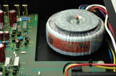
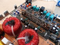
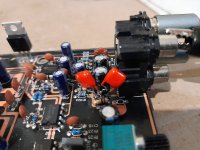
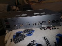
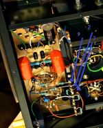
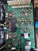
Early this year, I completed my first "from scratch" tube amplifier build. I used JE Labs 2A3 Deluxe schematic. Prior to that, I had only built kits (Audio Note Kit DAC 2.1, Bottlehead phono stage, Bottlehead Crack).

The JE Labs amp sounds great (to me!), but as I develop a deeper understanding of the ins and outs of tube amplifier circuit design, I suspect that I could do a lot better. (Those of you who hate two-stage driver circuits and/or 2A3s being driven by 6J5/6SN7, I've read plenty of your posts and am sympathetic to those views.)

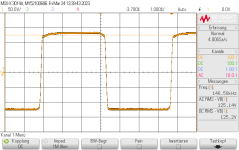
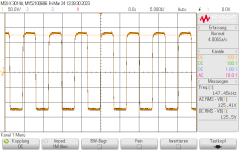
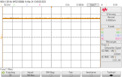
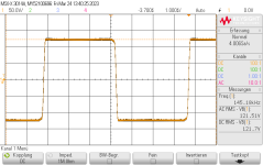
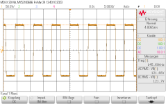
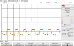
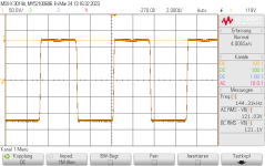
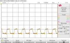
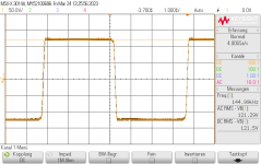
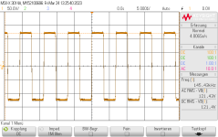
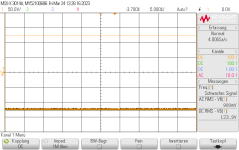
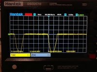
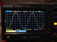
I borrowed a rudimentary oscilloscope from a friend and, during my short time with it, observed asymmetrical clipping near maximum output volume using a Type 76 tube. I'm guessing that that had to do with the 6J5 operating point but I am not sure.

Two issues that I want to explore (beyond making sure I have the fundamentals of the operating points down):
- Global negative feedback
- Lowering gain

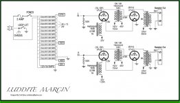
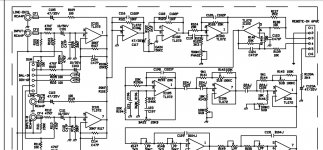
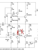
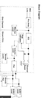
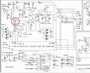
The circuit can be found here:
JE Labs Arkiv (up to 2008): JE Labs SE300B Classic and Deluxe

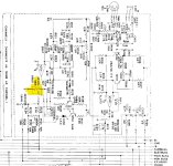
But first I want to know if I'm understanding the operating points correctly. I'm attaching a few images illustrating the following:
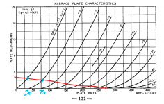
- Type 37 operating point (input tube)
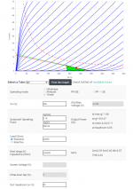
- 6J5 operating point (driver tube)
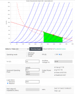
- 2A3 operating point

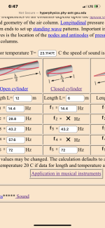
I hand-drew the type 37 since Universal loadline calculator for vacuum tubes - Vacuum Tube Amplifiers - DIY does not support the type 37.

The type 37 is biased at -2.2 V and swings between ~30V and 75V, with quiescent current @ 2.2mA.

The 6J5 is biased at ~-70V, the plate swings between 240V and 320V, and has quiescent current @ 3.18mA.

The 2A3 is biased at ~-50V, the plate swings between 270V and 420V, and has quiescent current @ 56.8mA.

I determined the quiescent current by dividing the voltage at the cathode by the cathode resistor.

The "Universal Load Line Calculator" shows that the 6J5/6SN7 operating point is pretty awful. It may actually be worse than the chart shows, since I am unclear on whether or not the "load" that I enter into the "Universal Load Line Calculator" should just be the anode resistor (22 kOhm) or the anode resistor + the cathode resistor (44 kOhm). If I use 44 kOhm, the load line is really atrocious.

6J5 Operating Point?
At this point, I'm not sure what's preventing me from changing the quiescent current of the 6J5 to ~6 from ~3 mA. On the load line calculator, that change moves the 2nd harmonic distortion from 4.39% to 1.22%. This would simply involve modifying the cathode resistor (I believe?). But if I do that, do I compromise the operating point of the 2A3? I'm not against also modifying the 2A3 operating point--I just don't know what happens with the 2A3 if I change the operating point of the 6J5.

Too much gain? Negative feedback?

As I mentioned, the amp sounds great, but I believe I have too much gain. My DAC is ~2V RMS out and the volume control on the amp doesn't need to go much higher than 10 o'clock for things to be pretty loud. I suppose that means I could implement some global negative feedback into the circuit to control that? It would be a fun exercise to implement a switch which would let me turn the feedback element on/off at will to see how it affects the sound.

Otherwise, would moving the overall operating point of the 6J5 "to the left" accomplish a reduction in gain? Or, just by virtue of the tubes used, is the amount of gain present in the circuit set in stone?

Other options?
Obviously one option to pursue is a CCS for the 6J5 and use it to establish a constant operating current of ~6 mA, which should keep it (for the most part) below max dissipation.

For those that want to suggest I scrap it and start over with a single-stage driver--eventually I would like to do that, but for now, I want to move incrementally and see how changes to the circuit affect the overall sound and performance.

Thanks for your time!
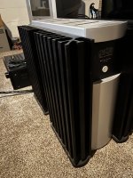
Attachments

  • 6J5 Operating Point.png
    6J5 Operating Point.png
    103 KB · Views: 250
  • 2A3 Operating Point.png
    2A3 Operating Point.png
    87.7 KB · Views: 243
  • type37_operating_point.png
    type37_operating_point.png
    93 KB · Views: 253

Trying to Understand Ground Loop Problem

Hello--

I know there are a lot of posts about this. I've read them over the past couple days and am still having trouble formulating a plan to correct an issue with my latest amplifier. It sounds great but am hunting down a 60hz buzz I can hear from the speakers--not very loud, but loud enough to hear from the couch.

In particular, I'm not sure I understand signal where signal in / signal out / potentiometer housing / chassis fit in. Am soliciting advice so I can minimize time wasted chasing this down and try to educate myself.

On the bench, when this was all just a mess of sockets and wiring, I could easily ground every connection at a single point. It was dead silent. Transferring it to the chassis, I haven't been able to easily accomplish that same approach. An extra challenge to this build is constructing the amplifier out of a chassis with separable top and bottom, and have wires which need to connect from bottom to top and vice versa.

Attaching a diagram of my power supply and grounding scheme. The line on the right hand side is a small length of copper wire. This is a 45 amplifier driven by gyrator-loaded 6N23P. I am using Rod Coleman regulators. So "Cathode x4" is a bit simplistic, indicating the following:
  • 2x 6N23P cathodes connect there as separate connections
  • 1 wire bringing the left 45 cathode + cathode resistor + cathode decoupling capacitor + grid leak resistor
  • 1 wire bringing the right 45 cathode + cathode resistor + cathode decoupling capacitor + grid leak resistor
TheBartola gyrator board grounds (2 of them) also connect to the bus bar.

From there, a single wire goes to a terminal strip which is connected to signal in (1 pair of RCA, 1 bluetooth PCB module) and signal out (the output from my Alps potentiometer, which has a metal housing). I have a DPDT switch to toggle between RCA in and bluetooth in. Bluetooth is L-C-R molex.

I have the potentiometer housing grounded to the bus bar, as you can see, and because of this, the chassis is also connected to the bus bar.

The IEC inlet ground plug is connected to chassis near the IEC inlet.

Heater center tap is virtual, constructed with a pair of 220 ohm resistors.

Not pictured: bleeder resistor across C4; 30 ohm resistors between rectifier (+ and - ) and C1.

My thinking is that I need to correct C2 -> C1 and make it C2 -> C3. That seems to be the correct approach here. But is that all I need to eliminate the buzz? I feel like there's something I'm missing involving the signal grounding and/or heater CT.

Really appreciate any advice!

1665800191926.png

My attempt at a JoFo

Perhaps this fits in the FAOW or Mofo threads but at this point it deviates a bit.

I am playing with some more flea-power ideas and was selecting a front end to add some gain to my mini-mofo.

And in the spirit of throwing stuff to the wall and seeing what sticks, I got the idea that perhaps we can replace the mofo biasing network and the input cap with a JBOZ style input stage. You can see what I came up with in the attachments below.

We basically have a JBOZ kind of input with its mid-point set at the biasing V for the output mosfet (4.5ish V). By removing the coupling caps, we bias the mosfet. But at the same time we significantly limit the undistorted output because the midpoint is set asymmetrically very low. Gain and biasing is configured by changing R6 which makes everything a function of the PSU V.

In the attachment, with 0.15V input the amp is already starting to clip. Green is Vin, blue is Vout, red is power at the load and cyan is power at the mosfet

The J113 is running at around 15mA and 100mW max with a 20x gain, while the IRF510 is biased at around 450mA and starts clipping at just below 3V p2p (18ish W peak), which is ~1W of output (0,5ish W RMS)

With a 12V PSU, the gain was 8x at 7ish W peak on the mosfet.

One thing to note, is that the positive swing probably has to be limited with a couple of leds or something, in case someone forgets that this is a 1W amp and fries the mosfet because of the larger headroom on the positive side. Of course we could limit the PSU too (we probably won't)

Also, biasing is sensitive to R6 changes, so it probably has to be split to a resistor plus a trimmer for better control.

Can you please review my idea?

mini-mofo-jboz.JPG

Attachments

  • Like
Reactions: nicoch58

Test a crossover with REW or DATS?

I spent a torid time yesterday turning a working XO into a non working one. I wanted to alter various values and so had the thing on the bench and plenty of desoldering old and replacing new components in. And I somehow made a mistake. So spent rest of the day trying to fault find. I had no sound out of it....just some kind of feint music from the tweeter. Desoldered pretty much all I had done to be able to see all the traces clearly. Turns out I had a broken track on the ground circuit.
I have REW and DATS V3 and was assuming given greater knowledge how to use this gear I could maybe test an XO to see what's happening without having to keep pluggin it back into the speaker and amp?

First valve amp project

Ok, I'm learning so go easy on me! I've assembled a PCL86 amp using a boost converter and buck converters for the heater and HT powered by a 20a laptop charger.

I'm just using a plastic box for the chassis to experiment and will build a proper chassis with a wooden enclosure once I'm happy with everything.

I've was initially following this schematic with PCL82

Screenshot_20230225-190240.png

But then changed to this one
129890-414e6e67c4684d33dd0c3586d98c8efe.gif

After building the first schematic, something was clearly wrong. On testing, the audio signal was coming through the speakers for a few seconds at the time I'm before bring interrupted by a short squeal/blip noise which would keep repeating.
I tested the voltage on HT tea and noticed that it was going from the correct voltage and rapidly dropping away when the blip sound was heard.
The LED on the boost converter unit was dimming in time with this

I decided to rebuild using the simpler PCL 86 schematic and found the same result.
A suspected that the boost converter may be faulty so ordered another one.
I replaced it but the problem is still there.

I've tested the voltage with the valve in circuit, the speaker connected but without an audio signal input and the voltage is stable.

As the problem persisted with the second, rebuilt circuit, and the boost converter is new, I'm not sure where to look to troubleshoot. The only thing that has stayed the same are the smoothing capacitors after the boost converter. I've checked these as per the schematic and it looks right.

The the heater supply coms via an LM317 step down converter. I bought a ready built module for this, I intend to build the slow start circuit at a later date. I have noticed that the heaters glow white hot for about a second on startup. I will definitely be incorporating this.

Here's a video of what I'm getting. I've only rebuilt one channel for now. You can see the speaker popping. It stops when I switch off the power supply.

Login to view embedded media
Thanks!

Driving the that 2180 control ports

Hello,
I am currently designing a VCA based on the That 2180.
I am gonna drive the control ports directly with an opamp as specified in the datasheet. The question is what would be the "best" opamp for the job.
It needs to be quite, have a low output impedance and needs to be fast enough.

The datasheet mentions the ne5532 but in some design notes they even used the ad797.

I am using 2 VCA's and drive both of the control ports so I would need 4 opamps. Would be nice to use dual opamps (1 dual per that 2180)
so the opamp shouldn't cost to much also.

Ad797 and lt1028 are good but single packages and they are bloody hell expensive.

So next up in line would be the lm4562. (the same as lme49720?)
It's low noise/high bandwith/ low output impedance... looks good I think.

Ne5532 is also still possible but I think the lm4562 will be better and have lower offset voltages.

Any suggestions are welcome

TB W8-1772 in a Dallas II or in a MLTL

Hello everyone, I have a pair of W8-1772 and I want to make them a speaker but I hesitate between a Dallas II or a MLTL. The look of plans proposed by Tang Band do not please me. I also heard about the design that Bob Brines made for this driver but I don't see how to find it now that Bob is retired. If you have any opinions on the matter, don't hesitate and if you have any ideas or proposals don't hesitate either.

Seb.

<moderator edit: removed advertising for translator>

For Sale Audiotechnology big Sale 10A77+18H52

UPDATED THREAD
This is the end. Now it is because I have found something that will retire me and I really want to do it.

On the shelf I have lots of high quality and some of the best units for future projects that now won't be build and I have to sell them to make room, money and to get a deffinitive retirement.

For sale:

Audiotechnology Flexunits 10 A 77 25 10 pair. SOLD

Audiotechnology Cquence 18 H 52 17 06 SD - SOLD


Shipping and PP fees not included.


You can PM me your offer if you will combine more items I'm selling. Make a search because there are a lot.

Kenwood Model 500 and Heathkit AA-151 Active Crossover Setup

Hi - Apologies up front. I'll put the essentials first. Details further on 🙂 - This is the plan:

Audio source ==> Kenwood Model 500 Integrated Pre Out ==> Nakamichi EC-200 Active Crossover ==>

==> Kenwood Power In (< 200Hz)
==> Heathkit AA-151 Aux In to Power Amp Section (> 200Hz)

(Speakers: Bozaks and Altecs)

Questions:
1) On the Heathkit, is it ok to run a wire directly from the auxiliary input to pin 8 of the 6AN8? (Volume is controlled at preamp/crossover)
2) Can the 6EU7 and 6AU6 tubes be pulled? And/or other parts of circuits be disconnected?
3) There's a 33K resistor and 470K resistor/33uf capacitor in parallel on the Auxiliary input - Is this necessary?
4) Do I need to be concerned about component compatibility (voltages, impedances, etc?)

Additional mods considered for long-term project:
- lower wall voltage to 117vac via bucking transformer
- replace power cord and add IEC receptacle that includes fuse, capacitor & switch (taking front power knob and lamp bulb out of circuit)
- rework output tube bias for individual (or pair) adjustment
- rework power supply filters - lower capacitance / add choke
- add switch/circuit for UL/Triode (Class A) operation

Did I miss anything? ;-)

Thanks in advance.
Jeff

https://ia804702.us.archive.org/6/i...lifier Assembly and Operation manual_text.pdf

Cardioid subs application

Hi,
I plan to build a bunch of compact subs for indoor and outdoor events. One idea was to use a pair of force cancelling 12" or 15" per cabinet. But I see Cardioid more and more often....
Looking for help on gaining some knowledge and applications cardioid and super cardioid subs. If the is a better forum for this unique subject, please let me know. Any links would be appreciated.

Cardioid subs:
When are they needed?
When are they NOT needed?
What are the tradeoffs to consider?
What are indications that cardioid type subs needs to be used?

Thanks!

Is it possible to get MQA digital output by adding an adapter board to a MQA DAC?

It's not difficult to understand the principle of MQA if we know the HDCD. Both of them compress the high definition music into standard low definition format. Without a MQA decoder, music is played normally in standard definition. However, with a full MQA decoder installed, it can output much higher sampling rate music up to 768KHz. The key difference is that the MQA was designed in a more commercial way. They issue licenses to music makers, online-music suppliers, device manufacturers and software developers for different levels of decoding. It is a full business ecosystem.

It's true that the MQA is not a 100% lossless format though they call it master quality. However, after carefully listening to the MQA music files that I downloaded from 2L on my MQA DACs, I found:
1. The sound quality of high sampling rate MQA music is better than the standard lossless 44.1/48KHz CD format.
2. The sound quality of the MQA music is very close to the high sampling rate original music file.

By considering MQA could be the only master quality music source we can access for our daily music listening experiences (for example, Tidal...) so far, I have to say I'm really happy with MQA. The only problem I'm having now is that the MQA is limited to the analog output of the MQA DAC itself, I can not play MQA music on my favorite DACs and my other digital music devices. That's really not very friendly to our audiophiles. So, here is the question:
Is it possible to get a full decoded MQA digital output by adding an adapter board to a MQA DAC?

The answer would be YES from the technical point of view, There is no difficulty to design an adapter board adding to an existing MQA DAC to tap off the fully decoded high sampling rate digital music signals from the DAC. By installing a HDMIpi and optional FifoPi to this adapter board, it will have a very high quality lower jitter MQA digital output signals. But now, we got another question: is it legal?

To be honest, I don't know the answer, but I can list some of the facts:
1. The adapter board itself has nothing to do with MQA so it has no business with MQA licence.
2. The MQA DACs do have the licence to decode MQA streams.
3. The end users own the MQA DAC, so they have the right to modify the hardware whatever they want.
4. The fully decoded digital music signal is no longer in MQA format.
5. There could be some limitations to the digital output when MQA issued a license to the DAC manufacturer, but the end users don't have any contract with MQA so the limitations may not apply to the end users.
6. There will be no such question if we don't play the MQA music on the DAC over the digital output.

I'm looking for suggestions and comments

Regards,
Ian


DigitalOutputAdapterPCB
by Ian, on Flickr

Some existing design for DIY active 2 ways with waveguide/ controlled directivity?

Hello,

I'm lurking on the Neumann KH150 or KH120 designs. I wonder if there would be around some DIY project for a similar size / performance, designed for DSP+active amplification.

I would look for good FR on and off axis, hence the waveguide (I have seen Augerpro ones). Low frequency would not be the priority, as a subwoofer would be considered. Reasonably priced: about 300-400€ max for drivers ?

I have seen the Directiva ASR R1 project, but to toy around the Purifi woofer looks way too expensive. And I like the idea that Neumann and many others achieve top performance with not so fancy drivers.

I have some experience with DSP and active amplification with my LX-Minis. But I don,t have the skills to design from ground up.

JMF

AUDIOLAB 8000C preamp

Dear,
My AUDIOLAB 8000C preamp burns its input fuse ( T1A 5x20mm ).
Because its transformer ( a Nuvotem Teo ) has its primary shorted.
Alas, I could not find the diagram for the 8000C.
So, impossible for me to know the characteristics of its transformer.
And especially the voltage at its secondary output.
In order to chise a new trasfo
Hence my question...
If One of You had :
- this diagram with this voltage value ?
- or knew these voltages ?
And if he agrees to tell me,
I would be infinitely grateful to him !!
My greetings from France,
Raymond

Attachments

  • Transfo Nuvotem Teo (R) .jpg
    Transfo Nuvotem Teo (R) .jpg
    232.4 KB · Views: 444

LU1014D Modulated Cascode

I have been looking at the LU1014D cascode behavior and found an interesting "modulated cascode" circuit that preserves triode behavior and expands the Vds (and power) range of the composite SIT-like device.

The LU1014D has triode-like (SIT) behavior but suffers from a 24V source-to-drain voltage range and limited power dissipation capability. These limitations can be overcome by cascoding the device as in the FirstWatt F3 and more recently the LuDEF (https://www.diyaudio.com/community/threads/ludef.369990/post-6588632) and the LuFo Amp (https://www.diyaudio.com/community/threads/lufo-amp-39w-se-class-a-from-28v-rail.372679/post-6665040). However, all of those cascode circuits result in pentode behavior of the resulting circuit.

The three columns of the image below show:
  1. The LU1014 degenerated by 0.73 ohms source resistor, showing triode behavior.
  2. The LU1014 cascode of the FirstWatt F3, showing pentode behavior because of the constant voltage cascode.
  3. The LU1014 with a "modulated cascode", showing triode behavior almost identical to the degenerated LU1014, but over a 10X expanded Vds range.
The black lines show 8 ohm load lines.

Attachments

  • lu1014-cascode-collage-2.jpg
    lu1014-cascode-collage-2.jpg
    432.7 KB · Views: 665

Monster Power HTS5100 dead...need help diagnosing

HTS-5100

It died the other day. No idea why.


EDIT:

It was a bad transformer on the power board.

Had done some testing on it based on a repair video I came across for another 5100. There was no proper voltage at the secondaries.

Once I got it off the board I confirmed the primary had no resistance at all and must've failed internally.

I replaced it with the smallest torroid I had lying around (120/2X15 80VA) that measured just short of 18V on the secondaries when I powered it up on the bench.

I hooked it up to the board mains inlet and wired the secondaries in parallel for a test. It fired right up.

I had to get creative and jack the board up with more stand offs so I could tuck the bigger tranny in underneath. Good to go.

If I had never found this forum and started messing around with DIY 10 years ago, I probably never would have been able to fix it. Thanks DIYAudio!

Input solid state relays - need your advice.

I hope you can help me to choose two relays:

1) a NO relay for switching on the signal source before the preamplifier for my home hi-end. The sound quality is of cause the most important, low external noise is second prize is third, other specification demands how I build the rest of the circuit.

2) A NC relay where the sound quality is of no concern, but the low external noise is most important, the voltage demands would be nice if they match the NO relay.

I know there is a total lack of information, but please ask, since I have nearly no idea on what info is needed to answer my question.

GZPA 1.4K-HCX protection issue

Amp came in from a friend, who said his local techs couldn't fix the issue. Amp goes in protect as soon as You apply any signal into the RCA input jack. Idles fine with no signal.

CF1 obviously has exploded badly for unknown reason to me at some point and now there are 2 film caps in series (doesn't seem right to me)?! I can't actually tell what are the CF1, CF2, CF3, CF4. Firstly I thought they are film caps, but pulling out CF4 has showed it is a resistor on my both testers ? Schematic from this amp, the pre-amp input section is attached. I don't know how or why has CF1 exploded as it's used in the output, not in the input and i pretty sure my friend does not use the output signal RCA jacks. So what is CF1 ?

Lifting one of the ends of R21 on the driver board (the 4.7ohm resistor used in the prot circuit) makes the amp produce clean output.
Fitting it back, in reference to the secondary ground, once the relay clicks in, some kind of a half sinewave pulses on R21 can be seen and amp starts restarting/recycling in a loop.
Obviously there is an issue with the protection circuit. Nothing is in short but I have my doubts on the MAX transistor as this have been my experience in the past.

I really would not want to pull out the driver board, is there anything else I can check and are issues with the blown CF1 and the protection somehow connected to each other ?

Attachments

  • 0.jpg
    0.jpg
    929.6 KB · Views: 178
  • 1.jpg
    1.jpg
    1.1 MB · Views: 170
  • 2.jpg
    2.jpg
    849.4 KB · Views: 160
  • 3.jpg
    3.jpg
    842.1 KB · Views: 142
  • 4.jpg
    4.jpg
    577.9 KB · Views: 169
  • 5.JPG
    5.JPG
    220 KB · Views: 186

Verry good CD transport

Im selling my Cambridge 840c cd player transport. I always used this for transport becose it was milles better than my audiomeca mephisto. The player is in like new condition with original packing, manual, remote and power cord. The price is low becose one chanel if you use this for cd player is about 40-50% lower in output volume. I already have buy this player with this defect from my good friend. I never trayed to solve or repair this defect. But for transport it is truly verry, verry good and top sounding. Price would be 200eu plus 19,80 euro shipping inside EU.

Attachments

  • IMG_20230318_085350.jpg
    IMG_20230318_085350.jpg
    479.9 KB · Views: 136
  • IMG_20230318_085346.jpg
    IMG_20230318_085346.jpg
    536.5 KB · Views: 142
  • IMG_20230318_085302.jpg
    IMG_20230318_085302.jpg
    368.2 KB · Views: 137
  • IMG_20230318_085404.jpg
    IMG_20230318_085404.jpg
    372.8 KB · Views: 136
  • IMG_20230318_085338.jpg
    IMG_20230318_085338.jpg
    428.1 KB · Views: 121
  • IMG_20230318_085310.jpg
    IMG_20230318_085310.jpg
    375.5 KB · Views: 133

Volume pot as input to LM386 Amp - "potentiometer" working (poorly), "rheostat" not at all

So here's the deal. I have an LM386-based chip amp, and I'm trying to put a volume pot before the input. When I wire it as shown in the top image, the pot works (e.g., it controls the volume), but the "maximum" output (e.g., pot turned to "10" or "zero resistance"), I only get about 1/5 the expected volume output. Now, my hunch is that my pot value (1k) is too low, so even when "dimed," the pot is basically bleeding off a lot of the signal to ground.

My question is this - in the second schematic (e.g., not grounding the third tap of the potentiometer, essentially using it as a rheostat), the pot doesn't control the volume at all (at least, I can't hear any difference). Why is that? Wouldn't dropping a 1k ohm resistor (e.g., when the pot is set to "zero" volume or "full resistance") in the signal path have some effect on volume? Or are the pickup and amplifier impedances just too high to have 1k make a discernible difference?

I will test out a 500k pot when I get a chance, but I'd like to know the theory behind what's happening here.

Thanks in advance.


IMG_0848.jpeg

Newbie wanting Bal/Vol control on an old TDA2003 bridged amp

As a first project in 20 years, I'm re-purposing an old Cana-Kit amplifier as a desktop amp to drive bookshelf speakers for mp3, phone, PC, etc. It has separate volume controls for each channel that I'd like to replace with Volume and Balance knobs. Will simply replacing the existing pots with Rod Elliot's "Better Balance Control" work OK for the level of quality we're already dealing with? The TDA2003 chips are often described as "good", but definitely not the audiophile level most folks here are striving for!

Attachments

Hello from East Texas

Hello to all and thank you for having me on this forum. I have been lurking for some time but am now just getting serious about DIY electronics. My past experience involves loudspeaker building, reviving old thrift store finds and repairing appliance boards but I am in no way a tech. As a lover of music though I have always owned a decent system. I own more recordings than electronics but I have prudently collected, and sold, quite a few over the years (I wish I had those Cornwalls and LaScallas back, not to mention that pair of Altec 200W tube amps-who knew?(I was young and that stuff was old. Parenthesis within parenthesis-I should probably break out Brown's)) and would like to learn how to do board level diagnostics and repairs. Though most times way over my head I am amazed by the knowledge, talent and generosity of the members here, not to mention the overall civility of discourse. Thank you for that. One problem I have is that I used to be rich and now I am poor. I used to be able to walk into a high-end audio store and actually walk out with something. My last experience however was less than satisfactory. I wanted American made components but the 3k$ tube integrated from Pennsylvania failed so many times I sat it on a shelf and plugged in an old Yamaha integrated (I'm really a Suzuki/Pops Yoshimura kinda' guy). After the Rotel 855 cd drawer failed I fixed it but when that fix failed I just took the cover off and made a top-loader out of it. East Texas in a nutshell. I rolled up those Kimber speaker wires and replaced them with a twisted pair of 10ga. magnet wire my motor winder gave me. The Magnepan 1.6's from the same buy however have been one of the best purchases I have ever made and I am hooked on the planar dipole sound. Long story short my electronics are old and failing, I am old and failing, but hell, I can still do better than that and if not I have a good excuse. I have been looking through here for a gutsy high-current solid state amp design to drive these Maggies and what I have found so far that seems to fit the bill is the Wolverine but I would welcome any suggestions for an amp that will actually drive a 2 ohm load, one that I can afford and one that can deliver the performance I am used to. I am an old bachelor so I don't care if it looks like an ice chest as long as it works. I figure if I recycle some of these transformers and use some of these nice nos parts on hand I can do it for a thousand bucks and I really don't want to sell my only child into slavery to buy an overpriced glitz box that cost less than the crate it's shipped in 'cause they know UPS will be lugging the thing back in and drop it on the floor from waist height. (Okay-that might be an exaggeration but with poverty comes bitterness and I have actual experience, perhaps because it was delivered to a machine shop). Enough proselytizing though. In my limited time here I have gained much and hope to actually be able to contribute in the future. You are some fine folks-keep up the good work.

Help with potentiometer on this schematic please

Hi - I am looking to replace faders on a mixing desk from the early 1980s. They are tired and worn. I'm new at looking at schematics and would really appreciate your help and expertise on replacements.

The current faders are 88mm long with 60mm fader movement and are 10K B (which I think is a linear fader). They have been swapped out at some point (tell tale signs of additional screw holes a few mms below the top screw hole).

I think the schematic suggests 5K B faders (but as a newbie I'm not sure if I am even looking at the correct part of the schematic!?). I have included a block channel diagram and the schematic for the channel (highlighting where I think the fader is located).

My questions are - am I on the right track? And if so, is it best to put in 5K B faders as per the schematic? Or are there advantages or draw backs with going with 10K B. Or is logarithmic (Audio) taper instead of the linear (B) fader? Any recommendations for faders? Thanks so much for help.

Attachments

  • Channel fader.jpg
    Channel fader.jpg
    133.3 KB · Views: 150
  • Block diagram of one channel.jpg
    Block diagram of one channel.jpg
    55.3 KB · Views: 122

Could someone help with a Box Build

Could someone help me with this box build.

The speaker: Ds18 Slc8s 200rms 8ich 4omh
The Box: length: 122cm width: 31.5cm hight: 15vm(as small as I possibly can)

The plan is to have the sub in the middle of the shelf of the table and for the Ports to be semetrical on both side, I have drawn a diagram for the box im the way I would like, the question would it work?

Don’t mind the ply it will be Sanded and prepped once everything is ready. Also using 18mm ply

Attachments

  • 7938D4A9-047D-4810-A319-82B832ECC2D5.jpeg
    7938D4A9-047D-4810-A319-82B832ECC2D5.jpeg
    1.1 MB · Views: 135
  • 86A15B50-FA31-4557-A77D-2F177C517ED9.jpeg
    86A15B50-FA31-4557-A77D-2F177C517ED9.jpeg
    915.8 KB · Views: 139

XLR ground - Pin, spring or both?

Hi all,

Just wondering what the normal practice is for connecting an XLR cable?

In particular how you connect the ground. Ignoring the shield for a moment, there are two ground connectors. There's the pin and there's usually a connection for the plug casing if it's metal.

What is considered good practice? Ignore the casing? Connect both?

Thank you.

Counterfeit ELNA Silmic II or genuine Elna ???

Hi,
I have been ordering ELNA Silmic II capacitors for years (from Mouser), and to date all the Silmic II that I have received have a brown jacket.

Recently I have been obliged to order a few Silmic II from another store and curiously the capacitors do not have a brown jacket but a Black/Gold jacket that I had never seen before: see the attached photos.

Do you know if they are counterfeit or genuine Elna Silmic II ???


Thank you very much for your reply,

  • Locked
For Sale MiniDSP SHD (Full Analog I/O Version)

ASKING PRICE: $650.00 payment by PayPal friends & family, postal money order or personal check. (Must clear my bank before shipment)

I am selling my 4 1/2 year old MiniDSP with full analog and digital I/O. Purchased new in November of 2018 directly from MiniDSP in HK. It's in very good condition and was removed from service just today when my new SHD Studio arrived. I no longer need analog I/O since I use digital crossovers and mastering ADC for balanced analog inputs.

This unit has fully up to date FW, Dirac3 and fully configured Roon ready streamer. Comes with original remote control, IEC power cable, USB control/Audio cable, and the optional rack mounting ears. It does not come with a UMIK-1 or 2 mic which is required to do Dirac calibration. (My plug-ins will not be useful to the next user.) I can provide a brand new UMIK-1 mic separately if needed.

In very good condition, the OLED display has some burn in as this is an original 1st generation SHD and FW screen auto-off option did not arrive for several years.

Top.jpg


Front.jpg


Rear.jpg


Accessories.jpg

locking problems with CD transport

Hello
Just for fun, I decided to use my shigaclone cd transport to make comparaisons with files on computer. In the time I had a homemade dac which worked correctly with this Shiga. It used a CS8416 receiver. Now I have a DCS dac and it doesn't want to lock with the cd transport . If I use the transport connected in my Audio gd interface DI-20 connected to the DCS it works but I sometimes hear cracking noise like if I played a LP.
The output of the cd transport is 0.5V. As you can see, the square waves taken at the output of the transport at the end of a 1m coax are quite good. With my frequency counter connected to the output of the cd transport I read 1.79 MHz. What could be the problem ? Thanks.
20230421_120922.jpg
20230421_124508.jpg

Help please. Low volume Roksan caspian mk 1

Hello, I have an issue where im getting low volume on my Roksan Amp. I have bassically stripped it down as i want to restore it .Before i get the spray cans out id really like to get the amp working properly.As i really have no clue,where would i start looking.I have a multimeter and i can solder ok .


Thanks in advance

Mick

Attachments

  • 20230422_112614.jpg
    20230422_112614.jpg
    620 KB · Views: 201

Behringer EP4000 for H/T

I think I'm going crazy. I keep throwing money at this project and getting nowhere. Hoping someone can help.
I have 2-15" subs. Trying to power with the ep4000. I'm using the art clean pro box in line. The lights on the amp seem to be working good. I can go all the way to clipping and get almost no sound from the speakers, just a lot of heat. Not sure what I'm doing wrong. Any help on this would be extremely appreciated.

Yamaha TSR-7850
Art clean box pro
Behringer ultra gain pro mic 2200
MVX VSW154 V2 x2

GNF / LNF resistor values and general tube topology Q....

1st, I have added 2 toggle switches for R15 (LNF) and R16 (GNF) in the schematic below.

I think may be I would have liked a stepped attenuator's instead, (4 step at most if it exists) so I could go from the default value to off (leaving 1 set of resistors disconnected from stepped attenuator)
A low(er) volumes, I love the sound with zero feedback, for me its not even a close call. BUT zero feedback clips quicker (as volume goes up) for me...
When we are entertaining a small group all the way to having the house is loaded with guests, I could add in FB depending on how loud folks want the music...

Im unsure of how to set up an AC measurement on the feedback.
For example at C8, (what input test voltage should be, what the actual volume knob should be dialed to and lastly how the cathode voltage on the first 12AT7 might interfere..
I was thinking measure the V after C6 with LFB on and off and guess the difference was what was actually going through C8..
Then do same test with GFB...
Feeling like Im outside of my comfort zone... and didnt want to pull the amp out of service (enjoying SE again!)
figured I should ask the guru's!

With the schematic below (and a 4 step attenuator if it exists)
Im unsure of what the values should be for the 3 resistors on either the GFB/LFB circuit should be...
R15 @ 330k is by far the lowest resistance (Most FB) I would ever want, so I thought in series I could add some arbitrary values, call it value 1, then on the second step more resistance Value2 , 3rd even more and finally the 4th would be infinite resistance (no resistor).
Same for R16 and the GNF, would never want more fb., so would only like to add resistance ...

Anyone have a gut feel for what the R values should be (both GNF and LNF) ?

The 2nd Q, does anyone know the topology of of the QSN7 (cathode to plate) above.. is it cascode / cascade / other ?
Im getting reasonably good at understanding basic tube circuits, but this has me looking for a better understanding.
My take is the upper QSN7 is the voltage amplification while the lower adds more current, Am I close ?
Id love to find a tutorial showing the sine wave's phasing and realitve levels for each cathode, grid and plate ..

Attachments

  • gnf-topo.jpg
    gnf-topo.jpg
    306 KB · Views: 73

Wharfedale speaker 3XP and XP2 tweeters

Due to hearing problems (being almost deaf now due to working on jet fighters in the RAF in the 1960s) and having to listen to my Hi-Fi through hearing aids I have gone back to 1970s speakers which seem to sound better to me.
I have two sets of Wharfedale speakers one being Glendale 3XP and the other being Glendale XP2. Both sets fully working.
I prefer the treble sound from the 3XP as it is less harsh than that of the XP2 but I prefer the bass from the XP2 as that in the 3XP seems a bit one note and not as deep as the XP2. Both speakers have the same sized cabinets and I gather the mid and bass units are the same in both.
Can I therefore simply transfer the tweeters from the 3XPs to the XP2s using the XP2 crossovers as fitted or would that cause a problem?
Advice please.
Geoff.

Flags are back / new member information section

Pre-migration to XenForo, a flag next to each members name helped us all to see what an amazing, very much global community diyAudio is. A melting pot of cultures from around the world who all share the same fanatical passion for audio.

These have now been returned, along with a tidied up member information section that is to the left (desktop/tablet) or top (mobile) of every post. Changes as follows:
  1. The dropdown/dropup button has been removed
  2. 5 pieces of information are now shown on desktop/tablet (member title, membership upgrade status, join year, flag, website). The member's typed location details (if entered) appearing when hovering over the flag.
  3. Join year and website are not shown on mobile to save space
  4. Website has "www." stripped from it to reduce clutter
  5. The old "donation star" has been replaced with what feels like a more descriptive icon - a shield. This signifies the member has helped to protect diyAudio by contributing to its operating costs this year.
  6. The green online indicator over the avatar has been removed as it cluttered things up and didn't look great. Same with the OP icon which is not nearly as important on our site with long threads as other sites. Either might return in the future with a nicer presentation.
If you experience any issues with the new layout please post here or send an email to the helpdesk at contact@diyaudio.com.

For Sale Korg Nutube B1 Preamplifier

Hi, I have a mostly stock Korg Nature B1 Preamp. I've added isolation feet, board mounts and added mass/covered slots on the inner side of lid to successfully eliminate microphonics. I was using this with an Aleph-J and sounded great. I'm now using a tube amp and find the tube on tube action a little too much for my taste. Functions perfect, looks perfect and sounds great. Comes with stock 24v/0.5A outboard SMPS. Don't hesitate if you have any questions! Asking $300

IMG_0573.jpeg
IMG_0569.jpeg
IMG_0570.jpeg
IMG_0571.jpeg
IMG_0572.jpeg
IMG_0574.jpeg

Not to expensive SMPS with a few % bad reviews. Exchange Mosfets in advance?

Hey people,

I've got an adjustable SMPS with max. 48V/ 10A, bought at Amazon, brand/ model is "HJS-480-0-48". I want to use it as power supply for a class-D amp in stereo BTL mode driving two 6.5" Midwoofers (atm. I've got 5.25" midwoofers driven by LM3886 chipamps which are really loud enough (max. 60%, never tried more) but I just want to move more air). I think, I'd never really torture the PSU, but I've read a (or maybe two) review(s) where this specific SMPS broke down when driven near the max. current.

As I made a few little modifications (bigger & slower fan, internal mains power connection with on/off-switch instead of screw-terminal, exchanged a few electrolytics which measured below nominal capacitance) I took a look at the mosfets which are STW20NB50 with a continous Id of 20A @ 25°C. Should be OK ... or do those seem to be more than they are?

Anyway, I do not have this type of mosfet in my box, but I've got some which might fit, and which are 100% original.

So my first question, could I replace the STW20NB50 with IRFP460 or STW26NM60N?
My 2nd question, if the 1st one is a "yes": Never change a running system, or better be safe than sorry 😉 ?

best regards
Jochen

Does a bigger recess affect the sound?

I am currently building a pair of speakers where the diameter of the woofer is 177 mm (6,97 inches) and the thickness is 4mm (0,16 inches).
At some point in the future, I will probably upgrade to an other driver with a diamenter of 183 mm (7,20 inches) and a thickness of 6 mm (0,24) inches.

Since I know about the upgrade already, I am planning to make the big (183 & 6mm) recess from the start. To make the smaller driver flush with the baffle and look better, I am going to 3D print an "adaptor" that takes up the remaining space in the diameter and depth.

Would the above plan be likely to affect the sound? Or is it a reasonable plan?
Sorry for the probably stupid question, but I'm not sure whether flush mounting is only about aesthetics or whether it affects the sound.


Thanks already

The SIT-3X Amplifier

The birth of SIT-3X: Everything started in the at post #119 https://www.diyaudio.com/forums/pas...-mu-follower-amplifier-build-post6161792.html, in a thread which was originally oriented towards the FirstWatt SIT-2 mu-follower circuit. Along the way, I analyzed the circuit of the FirstWatt SIT-3 and discovered a simple circuit change that performs harmonic cancellation, including odd harmonics! After more analysis, simulations, and bench testing, I saw the posssibility of a very low distortion amplifier with no global feedback. Here are the expected specifications:

  • Output Stage: Source Follower Tokin 2SK182ES SIT + IXYS IXTN40P50 PFET.
  • Choice of front-end stages:
    • Buffered, folded cascode FE with no feedback loop
    • XA25 style FE: requires feedback from FEOut to obtain low impedance output.
  • No global feedback.
  • 25W-50W power output
  • Adjustable cancellation of both even and odd harmonics.
  • THD at 1 Watt, 1kHz into 8 Ohms < 0.02%
  • THD at 25 Watts, 1kHz into 8 Ohms < 0.5%
The "Sit Measurements Mu Follower Amplifier Build" provides important background leading to amplifer design presented here. Since forum members are requesting that the design be completed, I decided it was time for start this thread. In my next few posts I will present the current designs for the output stage, folded-cascode FE, and XA25-style FE. There are still issues to be resolved and parameters to be "tuned", but I think that PCB layout can start.

Frankenstein-ing a commercial sub

I could fit the unltimax 8" after I gut out the T3. The dimensions are right, even after bracing and lining it.
How would it cause the stock PR to behave? **** poor I imagine. I think it might be better to change it or at least cover the hole. https://www.parts-express.com/Dayto...-Subwoofer-2-Ohms-Per-Coil-295-508?quantity=1

Does an f3 of 43hz sound right in such a small sealed cube, of 0.8 CF in the PE site. When I measured I think it was 10" , no more than 11" cubed.

It sounds VVG as it is. But what fun is that? I can always turn it around later anyhow. The 8" underneath looks the part and sounds, but its pretty poor job with too much power (in other words not a lot).

Attachments

  • 20230422_004330[6434].jpg
    20230422_004330[6434].jpg
    305.4 KB · Views: 93

SPACE class A headphone amplifier: in pursuit of true dynamics

From my point of view, one of the most significant drawbacks of listening to recorded music at home is the compression of the dynamic range, which results in insufficient "contrast" compared to what is heard at a live symphonic concert. The equipment may play smoothly, but listening to it can be boring. Live sound is not always smooth, and sometimes it requires some effort to perceive, but it certainly cannot be called boring.
The changes in volume in a concert hall can take your breath away.
Can realistic sound like this be achieved with headphones?

After lengthy experiments with various amplifier schemes and PCB topologies, I believe I have figured out how to create a device that does not "steal" dynamics.
The main points are as follows:
1. It must be a solid-state amplifier because only this type can provide low output impedance and low harmonic and intermodulation distortion.
2. The amplifier circuit should operate in class A with a large and almost constant bias current, excluding modulation of the device's power consumption by the musical signal.
3. High output power is not required because typical headphones have a sensitivity of about 100dB/1mW.
4. High dynamic linearity can be achieved with a topology that makes the amplifier immune to external high-frequency electromagnetic interference, both at the input and output and in the power supply circuits. This is often neglected, but over the past 30 years, the intensity of external electromagnetic fields in large cities and the pollution of the power grid has increased thousands of times (cell phones, Wi-Fi, SMPS, energy-saving light bulbs, etc.). Simple solutions that worked well in old devices no longer work.
In my device, I used a custom CNC-milled aluminum enclosure. If you put a cell phone inside such an enclosure and call it, the call will not go through because the enclosure is capable of completely blocking incoming and outgoing radio waves. Ordinary enclosures consisting of separate panels connected by screws do not have this ability.

The listening experience of the device revealed the following distinguishing features:
  • At first, the sound may seem uncomfortable, and adaptation is required.
  • After adaptation, the amplifier encourages increasing the volume more and more. The most exciting sound, in my opinion, is achieved at SPL above 90dB.

Tech specs:
Input connector type: 2xRCA unbalanced
Output connector type: stereo 6.5 mm
Input impedance: 10 kOhm
Output impedance: <0.8 Ohm
Frequency response: 5-30000 Hz (-3db)
Gain: 10.8 dB
Channel imbalance: <0.2dB
Max output power: 200mW at 32 Ohm

spac-akg812-2.jpginside2.jpgb-w.jpgspace-audeze.pngspace-inside2.pngthd918hz.jpg
  • Like
Reactions: freddi

For Sale The big cap blowout

Hi guys and gals. For sale are some mostly nos a few lightly used for testing in a circuit capacitors for sale.

8-ROE 15,000@40v
10- BHC 15,000@63v
20-Kemet 15,000@63v
13-Kemet 10,000@63v
3-Vishay BC 15000@60v
4-Cornell Dubliner 18000@70v
2-Vishay BC 15,000@63v
4-Epcos 15,000@63v

$20 each plus shipping

I will be posting more 33,000mf capacitors later. Cheers.

Attachments

  • IMG_4359.jpeg
    IMG_4359.jpeg
    241.2 KB · Views: 97
  • IMG_4360.jpeg
    IMG_4360.jpeg
    256.4 KB · Views: 96
  • IMG_4361.jpeg
    IMG_4361.jpeg
    258 KB · Views: 96
  • IMG_4362.jpeg
    IMG_4362.jpeg
    257.5 KB · Views: 92
  • IMG_4363.jpeg
    IMG_4363.jpeg
    280.3 KB · Views: 90
  • IMG_4364.jpeg
    IMG_4364.jpeg
    302.3 KB · Views: 88
  • IMG_4365.jpeg
    IMG_4365.jpeg
    568 KB · Views: 89
  • IMG_4366.jpeg
    IMG_4366.jpeg
    284.4 KB · Views: 77
  • IMG_4367.jpeg
    IMG_4367.jpeg
    271.3 KB · Views: 85
  • IMG_4368.jpeg
    IMG_4368.jpeg
    357.1 KB · Views: 94
  • IMG_4369.jpeg
    IMG_4369.jpeg
    328.4 KB · Views: 92

Greenvalve 10y into 801a

Hi all,

This summer I'll be plunging into the greenvalve design with 10y driving 801a, through hammond interstages and SMPS power supply.

I'll follow the schematic but will use 4 rod coleman regulators for the filaments.

This is my first DHT build, and how bias works is still beyond me.

What would you recommend? Filament bias on 10y, maybe with SIC diodes, and how many volts? And what to do with the output stage?

Any pointers on filament topology and values for this circuit are most welcome!

Cheers,
Simon

Attachments

  • greenvalve-luddite-marcin1.jpg
    greenvalve-luddite-marcin1.jpg
    157.1 KB · Views: 1,062
Projects by fanatics, for fanatics
Get answers and advice for everyone wanting to learn the art of audio.
Join the Community
507,757
Members
7,887,068
Messages

Filter

Forum Statistics

Threads
406,168
Messages
7,887,068
Members
507,757
Latest member
jossdorn