Looking for Naim CD5 and/or CD 3.5 CD player schematics.
Naim keeps a tight lid on their schematics. But if you've got these and can spare PDF copy (copies), much thanks in advance!
Naim keeps a tight lid on their schematics. But if you've got these and can spare PDF copy (copies), much thanks in advance!
Which bits are you after, and why..?
You have to trace your own - but the basics are simple enough to explain.
You have to trace your own - but the basics are simple enough to explain.
I don't have either. I'm curious about the analog output section because the DAC used in both those CDPs, a weird Philips Bitstream device, has a simple Vout. Naim seems to have added a multi-pole filter (output) that goes well beyond the datasheet of that DAC. Overkill? Or a better buffer? In any case, I have a Harmon-Kardon multi-disc CD player that uses a similar DAC IC. Thinking about modding it for improved, Naim-like sound .
The TDA1305 is a very straightforward device - have a good read of the datasheet.
Anyway, Naim's strong suit (to my taste) has always been their analogue filter stage design in such things - and the layout is part of the brilliance.
These players use a 7-pole, Bessel alignment; the first pole comes from the feedback cap on the TDA 1305 datasheet; in the CD3.5 and CD5 it is followed by two, well-finessed, equal value Sallen-key 3-pole low-pass filters in series. That's it, that's all. Except that compared with many, the physical layout and power/architecture of signal 0v layout and supply rail decoupling is really-well executed - just replicating the schematic on veroboard, will not perform as well.
To get really-good performance from Sallen-Key filters requires attention to teh sensitivities of such a filter design; Sallen-key requires surprisingly-high opamp bandwidth, about 100x the output passband, and output drive capability (hence clean power decoupling a big part-of). The map, is not the territory, kind of thing.
Last edited:
Thanks for your feedback, Martin!
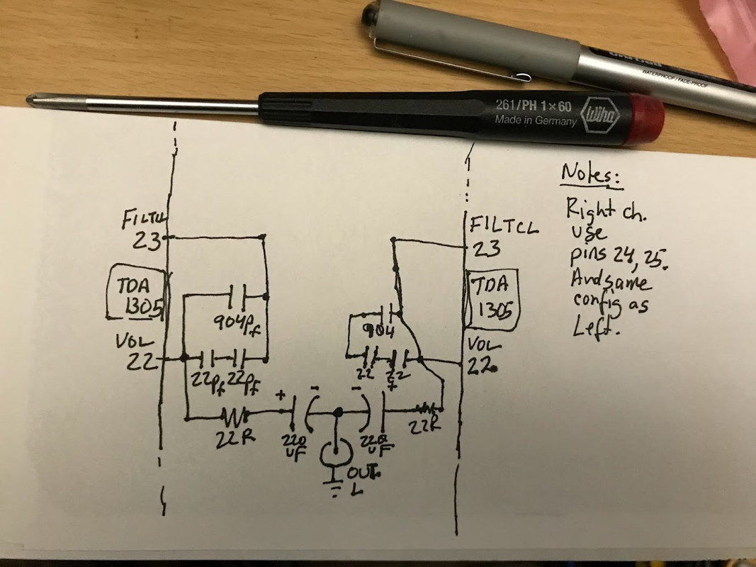
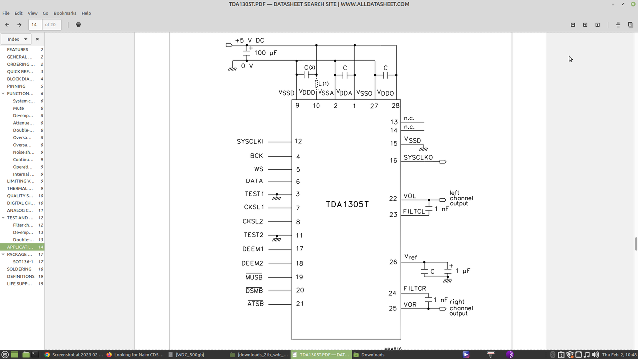
(The 1305 datasheet indicates the DAC has "internal" opamps; VOL (pin 22) and VOR (pin 25) are each, respectively, tied to pin 23 and 24 for "channel 1st order filter function should be connected between pins". The datasheet suggests this cap to be 1nF. And this is full output -- nothing more is necessary???)
I have a weird Chinese USB/SPDIF dac kit -- with two 1305 DACs used in parallel.
In that kit, there is equally weird output section that uses NO external opamps. Rather, some sort of resistor-capacitor network with 220uF output electros -- these caps (DC blockers I assume) are in series with the output jacks.
I thought all this was overkill so I hacked the kit, JUST using the datasheet-suggested circuit, but kept two 1305s in parallel. This heavily muffled the sound and gave me 2.5v DC at the output.
Restoring the orig Chinese circuit restored the decent sound (and output DC back mV) . But I have no clue as to why the 1305 datasheet circuit does not work????
The TDA1305 is a very straightforward device - have a good read of the datasheet.
(The 1305 datasheet indicates the DAC has "internal" opamps; VOL (pin 22) and VOR (pin 25) are each, respectively, tied to pin 23 and 24 for "channel 1st order filter function should be connected between pins". The datasheet suggests this cap to be 1nF. And this is full output -- nothing more is necessary???)
I have a weird Chinese USB/SPDIF dac kit -- with two 1305 DACs used in parallel.
In that kit, there is equally weird output section that uses NO external opamps. Rather, some sort of resistor-capacitor network with 220uF output electros -- these caps (DC blockers I assume) are in series with the output jacks.
I thought all this was overkill so I hacked the kit, JUST using the datasheet-suggested circuit, but kept two 1305s in parallel. This heavily muffled the sound and gave me 2.5v DC at the output.
Restoring the orig Chinese circuit restored the decent sound (and output DC back mV) . But I have no clue as to why the 1305 datasheet circuit does not work????
Below is a very quick and crude hand drawing of the Left channel circuit, from part of the two-tda1305 parallel Chinese dac. Refer to tda1305's datasheet for more info.
Yes, that works as a bare minimum
(and I'd trust the Chinese dac thingy as about 1/100th as far as I could throw it)
So - question remains: what are you wanting to achieve? And from what basis?
(and I'd trust the Chinese dac thingy as about 1/100th as far as I could throw it)
So - question remains: what are you wanting to achieve? And from what basis?
The $33 USD Chinese kit is not bad (stock) and is easily mod-able for improved performance. FWIW: It does feature that unique parallel 1305 arrangement.
The 1305 seems to have a lot of potential in the rhythm-n-pace dept. -- maybe why Naim used it?
I did have a look some photos of Naim 3.5 and 5 owners have posted on forums.
https://pinkfishmedia.net/forum/threads/naim-cd3-5-mods-not-on-acoustica.166556/page-4
The quality of parts and robustness of construction looks very good. However, I do wonder about those components spread out over a fairly W I D E are across the pcb. I.e., long traces. The Chinese board is very compact, so possible advantage. I'm a big fan of verboards and dead-bug (3D) construction. Keeping those traces and short and thick as possible. Yes, my projects look ugly. But that's why they call it DIY.
Note: Someone on PFM did mention bypassing 3.5 or 5's output and getting interesting results.
Yes, possible!maybe to avoid a DC offset due to the difference in operation of the two tda1305s
BTW: The datasheet notes:
V_FS(rms) full-scale output voltage (pins 23 and 25) (RMS value): 1.425 - 1.575 V
Anyway ... what the parallel design does is unique and sounds very good stock. I haven't experimented with single (non-parallel) 1305 yet.
I think the Chinese kit was meant to played with as it has marked (solderable) inputs for stuff like I2S and mclk.
The ONLY clock on the Chinese kit is a 4-pin 12mhz osc, which feeds a cheap CM108 USB chip, which then feeds a clock signal to a CS8412 which (internally) synthesizes a 11.28 MHZ mclk for the TDA1305's. Tent clock time!
And independent PSU regs can be wired to pins of the 1305 quite easy with:
- V DDD, pin 10, digital supply voltage
- V DDA, pin 1, analog supply voltage
- V DDO, pin 28, operational amplifier supply voltage
So .... there is much potential for improvement option there with the Chinese kit

"Green" forum? The color scheme over there looks like a blue-green on my monitor! Anyway: I just found your post here on DIYA:
https://www.diyaudio.com/community/...to-stand-alone-dac.374577/page-9#post-7031718
But this is NOT the Naim CD3.5 or 5, which have the Bitstream DAC that I'm interested in.
https://www.diyaudio.com/community/...to-stand-alone-dac.374577/page-9#post-7031718
But this is NOT the Naim CD3.5 or 5, which have the Bitstream DAC that I'm interested in.
The quality of parts and robustness of construction looks very good. However, I do wonder about those components spread out over a fairly W I D E are across the pcb. I.e., long traces. The Chinese board is very compact, so possible advantage.
Haha - no.
The map, is not the territory.
I doubt that. The CS8412 derives MCLK from the incoming SPDIF signal.The ONLY clock on the Chinese kit is a 4-pin 12mhz osc, which feeds a cheap CM108 USB chip, which then feeds a clock signal to a CS8412 which (internally) synthesizes a 11.28 MHZ mclk for the TDA1305's. Tent clock time!
Crikey, the cs8412, I'd missed that - is that even still a thing?
It was a lousy choice even when new nearly 25yrs ago...
It was a lousy choice even when new nearly 25yrs ago...
Yes, I think you might be correct. The CM108 datasheet indicates I2S for digital data out.I doubt that. The CS8412 derives MCLK from the incoming SPDIF signal.
However, Pin 20 is curious: "pin # 20 ADMCLK, DIO, 4mA, SR, 11.2896MHz Output for 44.1KHz Sampled Data and 12.288MHz for
48KHz Sampled Data." Not sure about this pin.
(The CM108 is also a crude audio DAC with low-fi L/R analog outs).
The Chinese kit does include USB, Toslink and Coax SPDIF inputs. And the CS8412 handles all three, which it sends to the 1305. The MCK out (CS8412):
"Phase Locked Loop --- MCK - Master Clock, PIN 19. Low jitter clock output of 256 times the received sample frequency."
So the MCK varies based on received sample freq. ??? Anyone know? Not sure what this means (I have not taken any measurements of the MCLK on the 1305). What's the best strategy for using an dedicated clock (like Well Tempered or Tent) ?
TDA1305T datasheet notes:
SYSCLK, pinI 12, system clock input
The TDA1305T accommodates slave mode only, this means that in all applications the system devices must provide a system clock of 256 or 384f s (f s = 32, 44.1 or 48 kHz).
Ultimately, I plan on using a better USB/I2S converter, so I can bypass the CM108 and CS8412 entirely.
Speaking of CS841x devices, the one from diyparadise (Monica) used an 8414. And fed the I2S outs to an ACT374M glue-logic chip for re-clocking. The clock input on the ACT was an external 80MHz 4-pin osc! The claim was the higher MHZ osc performed better for re-clocking w/ the ACT.
The Crystal CS841x devices are old, but they have some decent features such as independent digital and analog supply Vcc and GND pins.
I'm going to assume that if one wanted to experiment with a 3rd-party clock (DIY, like Well-Tempered, Tent, Audiocom, etc) for the tda1305 Chinese kit, then the approach would be the "common" tweak of feeding that clock to a re-clocker circuit (for the I2s lines, just before DAC).So the MCK varies based on received sample freq. ??? Anyone know? Not sure what this means (I have not taken any measurements of the MCLK on the 1305). What's the best strategy for using an dedicated clock (like Well Tempered or Tent) ?
- Home
- Source & Line
- Digital Source
- Looking for NAIM CD5 and/or CD 3.5 CD player schematics