Since I got a bit addicted to 3D printing and I yet have to try a line array speaker, I put this on my project list. And I hope it will be ever finished, too") I really like the 3FE22 driver and I tend to use it quite a lot in my other projects. So I imagine a 3D printed enclosure for this driver (or for a pair or quad) that could be easily stacked to form a line array. The 3D printed enclosure can be made light and strong and non resonant with minimum effort. PLA should work for home use and I am at the moment getting some really good quality prints that would not need any surface finish. I imagine this being held together maybe by hidden M4 threaded rods or long screws with buried square M4 nuts.
I really like the 3FE22 driver and I tend to use it quite a lot in my other projects. So I imagine a 3D printed enclosure for this driver (or for a pair or quad) that could be easily stacked to form a line array. The 3D printed enclosure can be made light and strong and non resonant with minimum effort. PLA should work for home use and I am at the moment getting some really good quality prints that would not need any surface finish. I imagine this being held together maybe by hidden M4 threaded rods or long screws with buried square M4 nuts.
The basic plan is:
1) order some 3FE22 - check
2) design a 3D printed stackable enclosure and a bottom plate - WIP
3) print many of them
4) enjoy the line array sound
The tested STL models will be of course shared here. This is a long term project, but my 3D printing skills are finally high enough to start the project
I really like the 3FE22 driver and I tend to use it quite a lot in my other projects. So I imagine a 3D printed enclosure for this driver (or for a pair or quad) that could be easily stacked to form a line array. The 3D printed enclosure can be made light and strong and non resonant with minimum effort. PLA should work for home use and I am at the moment getting some really good quality prints that would not need any surface finish. I imagine this being held together maybe by hidden M4 threaded rods or long screws with buried square M4 nuts.The basic plan is:
1) order some 3FE22 - check
2) design a 3D printed stackable enclosure and a bottom plate - WIP
3) print many of them
4) enjoy the line array sound
The tested STL models will be of course shared here. This is a long term project, but my 3D printing skills are finally high enough to start the project
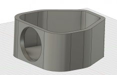
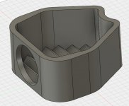
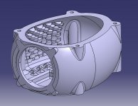
I have just put together a simple test module to calculate the material needed. Without any optimization, one would print in ca 17 hours and 4 could be printed from one spool. The wall thickness is 10 mm and the divider is 8 mm - the outer shell will stay at least this thick, the separating layer will be definitely less.
For a 25 driver array I will need 50 pieces which would total in ca 18 days of printing 24/7 and 7 spools of filament per speaker. So the shell should weight around 7 - 8 kg including the base with another 6 kg for drivers. A bit time consuming, but certainly feasible. So the total weight should be less than 15 kg per speaker including polyfil, terminals and wiring. The enclosure should cost around 1/4 cost of the drivers. I hope the structure will be rigid enough and I will most probably run a threaded rod through the whole speaker with nuts and spacers at every module bottom. Maybe even two. The size would be M6 or M8, and still should not add too much to the total weight.
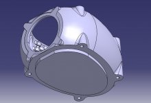
The 3FE22 will be flush mounted from outside, I am not sure if I will like the look, so I will think about adding some sort of cloth cover into the front.
It will take a few test prints to make the seams as little visible as possible. With 0.2 mm layer height this should be definitely doable.
This project will end up in the living room as main speakers as this is the only form factor that will fit the front wall. The left speaker will replace a green plant, but I will not tell my wife yet
For a 25 driver array I will need 50 pieces which would total in ca 18 days of printing 24/7 and 7 spools of filament per speaker. So the shell should weight around 7 - 8 kg including the base with another 6 kg for drivers. A bit time consuming, but certainly feasible. So the total weight should be less than 15 kg per speaker including polyfil, terminals and wiring. The enclosure should cost around 1/4 cost of the drivers. I hope the structure will be rigid enough and I will most probably run a threaded rod through the whole speaker with nuts and spacers at every module bottom. Maybe even two. The size would be M6 or M8, and still should not add too much to the total weight.
The 3FE22 will be flush mounted from outside, I am not sure if I will like the look, so I will think about adding some sort of cloth cover into the front.
It will take a few test prints to make the seams as little visible as possible. With 0.2 mm layer height this should be definitely doable.
This project will end up in the living room as main speakers as this is the only form factor that will fit the front wall. The left speaker will replace a green plant, but I will not tell my wife yet
Attachments
I've been trying to decide what project to do. I just don't know enough about speaker enclosures to be confident that I'm not going to end up with something awful sounding.
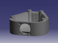
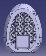
I start over thinking it and I want to add built in sleeves for the rods. Nesting profiles for mechanical interlocking. Egg carton patterns printed into the walls and floor to block resonance. Printed in flush mount for the speaker.
I start over thinking it and I want to add built in sleeves for the rods. Nesting profiles for mechanical interlocking. Egg carton patterns printed into the walls and floor to block resonance. Printed in flush mount for the speaker.
Attachments
I see you have similat ideas as I do. The pattern on mine would be more similar to the low profile acoustic foam so that the curves are smoother for easier print. The nesting on mine would be around the whole top/bottom with 45 deg chamfer for easier printing. The final shape will be also more similar to yours or wesayso's TC9 array. And mine will be nost probably held together by a series of screws.
I am now investigating driver alternatives.
A line array like this is easy - the volume needs to be around Vas and then it is just the shape. The rest is production. A line array like this needs EQ - in wesayso's monster thread there is a lot of information.
I am now investigating driver alternatives.
A line array like this is easy - the volume needs to be around Vas and then it is just the shape. The rest is production. A line array like this needs EQ - in wesayso's monster thread there is a lot of information.
Too many typos in the morning, sorry.
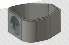
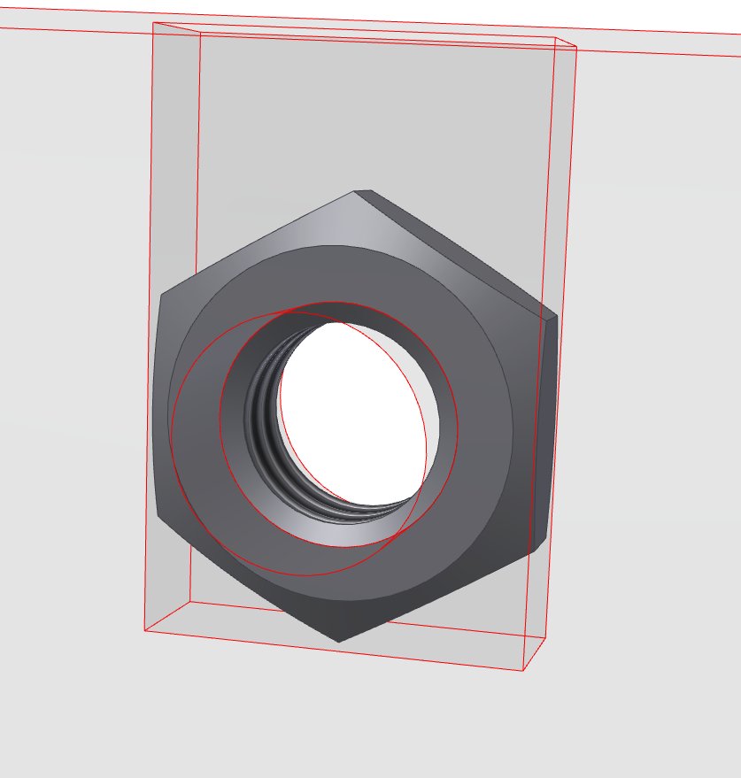
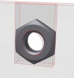
I imagined something like shown in the attachments. And instead of using sleeves for the rods, I would use nuts both from top and bottom of the divider, providing strenght in both directions. The final product will be most probably glued together.
I imagined something like shown in the attachments. And instead of using sleeves for the rods, I would use nuts both from top and bottom of the divider, providing strenght in both directions. The final product will be most probably glued together.
Attachments
I wonder if this style of loudspeakers would work well in a line array: Buying a Dayton Audio HARB252-8 woofer? | SoundImports - SoundImports
I think you could stack some of these "single units" to use the whole Z (height) direction of the printer? Less work gluing afterwards...
Most important... there is a lot of possible variations there. I like the "egg crate" idea - must not be pretty as it is inside. Or print only the complex front panel and attach that to a simple wooden box, or some (custom made) u-profile.
I think it was member "fluid" that made 2 arrays, the second one with each driver in a separate chamber - apparently much better than sharing the same volume.
I am feeling inspired these days!!
Last edited:
Yes, there will be some options. I would like to have it fully 3D printed because that is least work for me My printer is 360 mm max height - in reality, the limit for my prints is that it can be made from one filament spool. On the other hand, I am not sure if I want to risk 48 h long prints.
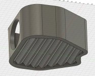
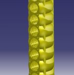
I have a crazy idea for the dividers. 3D printers like 45 degrees, so the divider does not have to be flat, but can be made of a few smaller hollow pyramids or maybe just triangular wedges and reduced in thickness as the pyramids/wedges will provide structural strength.
While thinking about it, the wedges would be definitely easier to print and would allow for better screw/threaded rod placement.
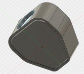
Also the presented footprint shape is not the final one, I would like to have something like a cut-off teardrop shape, to have one single curve from the front to the back. It needs to look great. I imagine silver PLA at the moment, but it can change anything between white and black.
Edit: This thread was indeed inspirational The making of: The Two Towers (a 25 driver Full Range line array)
My printer is 360 mm max height - in reality, the limit for my prints is that it can be made from one filament spool. On the other hand, I am not sure if I want to risk 48 h long prints.I have a crazy idea for the dividers. 3D printers like 45 degrees, so the divider does not have to be flat, but can be made of a few smaller hollow pyramids or maybe just triangular wedges and reduced in thickness as the pyramids/wedges will provide structural strength.
While thinking about it, the wedges would be definitely easier to print and would allow for better screw/threaded rod placement.
Also the presented footprint shape is not the final one, I would like to have something like a cut-off teardrop shape, to have one single curve from the front to the back. It needs to look great. I imagine silver PLA at the moment, but it can change anything between white and black.
Edit: This thread was indeed inspirational The making of: The Two Towers (a 25 driver Full Range line array)
Last edited:
I would suggest removing the parallell sides in the enlosure, especially the backwall. I would also put in big diffraction patterns on the inner walls which would also strengthen the cabinet. Triangular wedges on the inner wall sounds interesting! Features that serves 2 or 3 purposes is often achived with 3d printing From other designers on YT I've seen that wider walls with moderate infill will dampen wall resonances effectively.
Also don't make a super advanced box with perfect tolerances since plastic schrinkage is a huge problem when printing large things. So avoid designs where parts needs to go together perfectly, instead use CA glue to hold parts together. I would also avoid small details that creates a lot of retractions since that increases the probability of filament failiure. It's very annoying to se 20 hours print fail just before completion.
I am looking forward to your next box iteration so please post more pictures
From other designers on YT I've seen that wider walls with moderate infill will dampen wall resonances effectively. Also don't make a super advanced box with perfect tolerances since plastic schrinkage is a huge problem when printing large things. So avoid designs where parts needs to go together perfectly, instead use CA glue to hold parts together. I would also avoid small details that creates a lot of retractions since that increases the probability of filament failiure. It's very annoying to se 20 hours print fail just before completion.
I am looking forward to your next box iteration so please post more pictures
This is how I would not want it to be, honestly. Look at the back of the cone, imagine the wave front that comes from it, now look at the series of possible reflection surfaces you created...
You want the energy to move away from the back of the cone as freely as possible, not be reflected back to it.
Lots of people see the wavy shape of my enclosure and think: it is to break up the internal wave front. Well, these are small shapes so it would only work well at higher frequencies, the frequencies that are easily absorbed by damping material. But don't forget the outer shell. I did create a varying thickness of that outer shell.
Thanks for the feedback! So you would recommend waves instead? Or just plain flat? Uneven wall thickness is relatively easy with 3D printing. Also, it is reatively easy to arrange the surfaces inside in a way that nothing is really parallel. And maybe add some internal structure to break up the waves even more - like a sphere, elipsoid or even just a cone if that would make any sense.
Honestly, I am not confident in acoustic design at all. I am more aware of the 3D printing rules.
Honestly, I am not confident in acoustic design at all. I am more aware of the 3D printing rules.
3D Printing offers you so much more freedom. Just start using it. You can make every bend or corner flow instead of having hard transitions.
I do a lot of 3D printing at work. The first thing I teach my students is to start thinking what the freedom in 3D printing brings you as a designer.
I see a lot of square corners etc. in designs for 3D printing. Why would you do that? You can make it more organically shaped without it costing you anything. Stop thinking of the shapes you see in conventional designs/engineering and start thinking of what's possible with this new found freedom.
You could still use grooves, but let them move/flow away from the cone. Have them flow with the outside wall (front to back) and use fillets instead of the sharp bends.
Think more in organic shapes, somewhat like Gaudi used here:

The outside shape can be whatever you need, it doesn't need to be traditional or have any flat surfaces, you can make is fit the speaker you choose perfectly and shape the outside for a continuous shape that starts at the cone. No hard edges or flat planes anywhere. Be more creative with the design freedom 3D printing gives you. (I'd use back mounting and have the outside flow in one line starting with the cone shape)
At least, that's my advise. You don't need to take it. It's what I would use.
Use everything you can to avoid diffraction, that was my personal goal.
I do a lot of 3D printing at work. The first thing I teach my students is to start thinking what the freedom in 3D printing brings you as a designer.
I see a lot of square corners etc. in designs for 3D printing. Why would you do that? You can make it more organically shaped without it costing you anything. Stop thinking of the shapes you see in conventional designs/engineering and start thinking of what's possible with this new found freedom.
You could still use grooves, but let them move/flow away from the cone. Have them flow with the outside wall (front to back) and use fillets instead of the sharp bends.
Think more in organic shapes, somewhat like Gaudi used here:
The outside shape can be whatever you need, it doesn't need to be traditional or have any flat surfaces, you can make is fit the speaker you choose perfectly and shape the outside for a continuous shape that starts at the cone. No hard edges or flat planes anywhere. Be more creative with the design freedom 3D printing gives you. (I'd use back mounting and have the outside flow in one line starting with the cone shape)
At least, that's my advise
. You don't need to take it. It's what I would use.Use everything you can to avoid diffraction, that was my personal goal.
Attachments

I lost a previous reply, in which I had made another observation. Personally I like some weight in an enclosure to offset the moving mass of the drivers. I'd use/design slightly hollow walls that can be filled in with something like sand.
Edit: another thing that popped up... we usually use nuts that are hidden in our 3D prints. Just make clever openings to slide a nut in so you can mount anything you need. It can be hidden but easy to use:
It takes some test prints to figure out tolerances for the nut to slide in but it works once you know what to use.
Attachments
Last edited:
Very valid points. The backmounting is an option I also considered, that is why there is just a round hole. The outer shape will be some sort of spiral / curve. These will be printed on a delta style printer, so smooth curves are the best option.
Regarding the weight, I would be a bit afraid of the strength in the long dimension when glued together from pieces. I will let it sink in and try another shape.
Regarding the weight, I would be a bit afraid of the strength in the long dimension when glued together from pieces. I will let it sink in and try another shape.
I think I like designing them more than actually building them. I like to try to design things for 3D printing that can't be easily constructed with conventional manufacturing techniques. Instead of triangles, I was experimenting with rounded dimples on the floor.
If your printer is capable, you can consider using a 64D TPU filament instead of a PLA filament. Both for the acoustic properties and to reduce issues with shrinkage.
I was reading these forum posts about this line array.
The making of: The Two Towers (a 25 driver Full Range line array)
If your printer is capable, you can consider using a 64D TPU filament instead of a PLA filament. Both for the acoustic properties and to reduce issues with shrinkage.
I was reading these forum posts about this line array.
The making of: The Two Towers (a 25 driver Full Range line array)
Attachments
- Home
- Loudspeakers
- Full Range
- Modular 3D printed full range line array