TPU is flexible, isn't it? That would not work I think. I got an idea - inspired by B&W - to make an internal "snail" or maybe to make the unit a snail shell as a whole. For aesthetic reasons, I would like the outer shell to have the same footprint for all modules to have a column look. Yours look very interesting indeed. On the exterior look I need to consult my wife🙂
64D TPU is much more rigid than you would expect for a TPU. The much more flexible filaments are usually a 92A TPU.
Your eggs do have a 'Scaena' feel to it 🙂
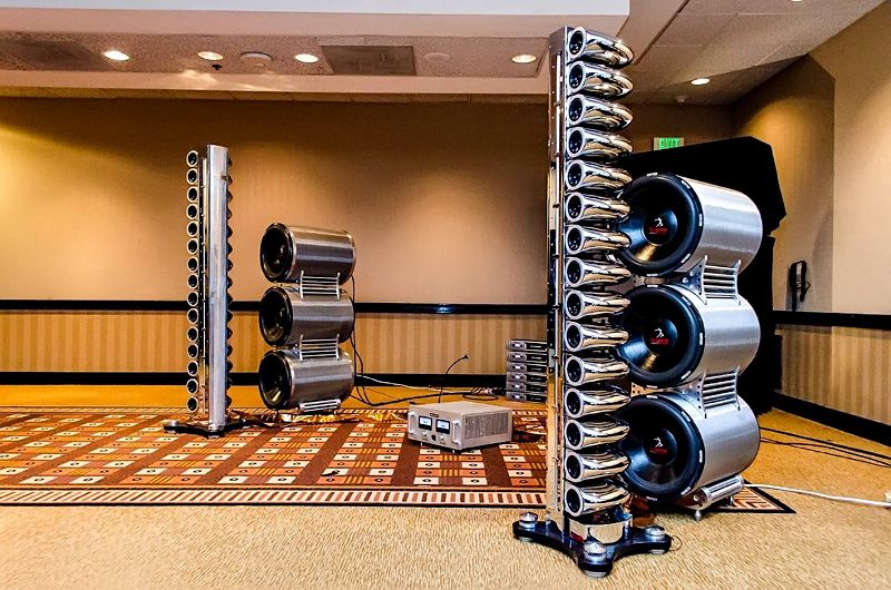
Not quite a snail shape but getting closer to it:

Link to Scaena speakers: Scaena :: Iso-Linear Array
Link to picture source: Scaena install | What's Best Audio and Video Forum. The Best High End Audio Forum on the planet!
Not quite a snail shape but getting closer to it:
Link to Scaena speakers: Scaena :: Iso-Linear Array
Link to picture source: Scaena install | What's Best Audio and Video Forum. The Best High End Audio Forum on the planet!
Attachments


Don't be afraid to use CA glue on PLA, several YT channels have tested CA glue to give more strength than the PLA itself when parts are touching each other. This is also my own experience. CA glue also works pretty good on PETG. I would look into epoxy glue for larger gaps.
The dimples idea looks cool but whould increase print time with all the extra extruder movements and cause many retractions. They would also only breakup ca 15kHz+ at best. What if you rotated the triangles 90 degrees and let them start 6-9 cm from the driver? The start could also be very gradual so no early reflection. The triangles would stiffen upp the bottom and the ceiling without costing to much material and print time. When using a lot of fillets in horisontal dimension one often need more support material than just a sharp transition. I'm often printing in Petg without a heating box(just a warm room and some spot lights) I tend to make my large designs bulletproof. So less overhangs and fillets. Looking at the Scaena speakers I think the sharp bend from speaker to cabinet side would create audible diffraction so I think your design is better. Having a smooth radius on the baffle is something I've started to belive in.
I've also considered a snail shape but the box gets large quick! It would cost a lot more and take a lot longer to print as well. I think the rounded front baffle is more important than the snail effect on sound in a fullrange. That said the bragging rights whould be pretty awesome on a snail cabinet 😉
I tested CA and liquid nails (Mamut glue) and it works well on PLA, PETG and rPET. So I am not afraid of the strength of the glue. Yes, the print must be reliable, so no overhangs with the exception of the driver opening.
Just a quick play with Euler spiral in Fusion 360. I wonder if it would be worth the effort. The only parallel surfaces left would be the top and bottom of successive modules. I think that would create a 1/4 wave resonance around 1 kHz. I have no good idea on how to make the top/bottom uneven. The only idea I have is that I could have two types of modules, each with different floor but keeping the total volume for one driver constant.
The outer shape could be made into anything non-diffracting with large roundovers, etc. so it is the inner arrangement that I am now thinking about.
The more I get into it, the more I think I will just use a plain simple easy to print box for the tests anyway.
The outer shape could be made into anything non-diffracting with large roundovers, etc. so it is the inner arrangement that I am now thinking about.
The more I get into it, the more I think I will just use a plain simple easy to print box for the tests anyway.
Attachments

Another problem is that the sound on the right side of speaker would be reflected back into the cone. I see many people at this forum try to avoid this and I wonder how audible this effect would be? Shouldn't the point be to get the standing wave out of the bandpass of the speaker or make the speaker play deeper?
Regarding the test box I would make the outer walls slightly curved since that is free cabinet performance with minimal effort 🙂 Some YT printed boxes have had huge problems with wall resonances making it difficult to evaluate the drivers tested.. A box resembling a pressure wessel should be used or else its quicker to find an old speaker box and just make an adapter plate.
Regarding the test box I would make the outer walls slightly curved since that is free cabinet performance with minimal effort 🙂 Some YT printed boxes have had huge problems with wall resonances making it difficult to evaluate the drivers tested.. A box resembling a pressure wessel should be used or else its quicker to find an old speaker box and just make an adapter plate.
Yes, the box will be definitely curved and simple shape. Still waiting for the drivers, so there is time left for design. I like the Euler spiral, so I will base it on that curve - just to see what I get.
Since my first order was placed for 8 3FE22s, I might try to make a line with just 8 drivers, inspired here: Application of golomb rulers to sparse line arrays
That would mean a totally different enclosure, more like the one from post #20, so it would be kind of egg shaped and held together by threaded rods. Without a common baffle at all. It would allow also to play around with fractal array configurations.
That would mean a totally different enclosure, more like the one from post #20, so it would be kind of egg shaped and held together by threaded rods. Without a common baffle at all. It would allow also to play around with fractal array configurations.
Unfortunately not. The idea is still on the to do list. The speakers arrived this week, still sitting in a box.
We are on a similar boat in that case: I have a few boxes of TC9s ready for when I have time. I will be doing a conventional design - inspired by the greats on this forum (they know who they are). Had been pondering materials and methods for a bit, but given the resources available, and diminishing returns, I will make regular speaker boxes do for the time being. However, there is something that tells me that a 3D printed modular design might be very interesting.
For something this large I wonder if you can get access to a “furniture grade” 3D printer used to print chairs and the like. It would go much faster and raw material might be less?
Hello!
I would like to jump into this thread to ask if there are some news.
I started a very similar project 3 years ago, but haven't been able to complete it yet.
I printed several enclosures, installed the drivers (TC9FD18), wired everything and listened for a while. I found them very pleasant but, unfortunately, I have not yet been able to complete them either from an aesthetic point of view (both me and my wife are very demanding, we can call it WHAF = Wife & Husband Acceptance Factor 🙂? ) or from an acoustic point of view (I have to carry out some good outdoor measures to understand the real potential of my speakers).
Thank you!
Manuele
Hello!
I would like to jump into this thread to ask if there are some news.
I started a very similar project 3 years ago, but haven't been able to complete it yet.
I printed several enclosures, installed the drivers (TC9FD18), wired everything and listened for a while. I found them very pleasant but, unfortunately, I have not yet been able to complete them either from an aesthetic point of view (both me and my wife are very demanding, we can call it WHAF = Wife & Husband Acceptance Factor 🙂? ) or from an acoustic point of view (I have to carry out some good outdoor measures to understand the real potential of my speakers).
Thank you!
Manuele
Hello Manuele,
Expect to need some EQ to make them sound their best. I can't say much about aesthetics, as I managed to get away with placing these in my living room.
That I like em, as I designed and build them is obvious, but I do feel very lucky that I get away with it to place them in our living room where they have been for
about 7-8 years now, in total. Obviously these aren't printed, but then again, it took me 1.5 years to build them!
If your stack is much smaller, it will react different than tall arrays like these, but as most of the work has done, running some simulations can help
understand the stack of speakers so you can make them sound way better.
A simulation of a 25 driver stack with my driver spacing looks like this in Vituixcad:
The above is without any EQ on it. That would sound "interesting" at best, but not beautiful. (note the grey in-room prediction)
With a little EQ we get a whole other picture which can actually sound quite beautiful:
Again, look at the grey predicted in-room frequency response. Key point is: they need EQ. And preferrably a smooth outer shape
to limit diffraction as much as possible. And if you're also willing to absorb early reflections off of nearby walls, it will only start to
sound better because of that. (absorbing panel behind that curtain in my picture).
Shorter arrays react quite different. Here's a sample of a 15 driver array, still quite tall:
Or even more extreme, look at a 4 driver array:
With an array like that, move even less than an inch up or down and you've lost all high frequencies! On the plus side it does not show any
evidence of combing 😉.
Most of the hard labor has been done already, to create a valid (Vituixcad) simulation of the TC9 arrays, pick up a starter project here:
https://www.diyaudio.com/community/...-corner-placement.337956/page-28#post-6205129
It's an older model, but complete and one can edit the measurements to suit their needs. I think it still has a floor mirror etc.
but it should be easy to use it and get going. It's what I've used for my own models, big thanks to @nc535 for giving this away
for us to play with.
It might be a bit much what I wrote here, but I promise it can be quite rewarding to get into it, especially with the help of
these modeling tools, to learn what to expect before committing. If you can get an acceptable form factor that both of you can like. 🙂
I tried to use: Form follows Function for my project. Meaning the shape was determined by it's function, with a little bling added
perhaps 😀
Last edited:
Hi Ronald!
What an honor to receive an answer after my first post from the person who most inspired and motivated me! 😀
I am truly grateful to you, and all the other "line array guys" for all the knowledge and experience you have shared on this (and other) forum.
I have read your posts and I am aware of all the problems / solutions you have handled, and still manage, on your epic journey to your very own acoustic "nirvana"!
My original idea was to print 25 boxes but the birth of my first child, and shortly after the second, didn't help my patience 🙂
So I started messing around with the Vituixcad model you posted. I did some simulations and, at least in theory, at my listening distance (5m) a 9 element array shows no signs of comb filtering. An accurate simulation can only be done after measuring the frequency response of the single box as accurately as possible and uploading it to Vituixcad in order to evaluate the overall response.
As for the vertical response, I am aware that I will have a very limited listening window. I would use my "mini" array as a bookshelf speaker, centered at listening height. For the moment, I was going to test the array "bare" without frequency of power shading, only to understand how annoying the vertical response can be. I need to concentrate on equalization and possible FIR. Leaving the external wiring will allow me to handle this problem later.
As a mechanical engineer, I always follow the "dogma" that form follows function, which is why my box design is rather "strange".
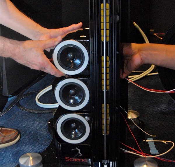
Only after several months of reading your thread, I found that my solution is VERY similar to the glorious Scaena IsoLine array 🙂 (but without the ribbon tweeters ...). This year I visited AXPONA 2022 and I can say that, of all the speakers and systems I have heard (worth several hundred thousand dollars), the Scaena was on another planet (maybe I'm biased by my array? 🙂) .
Thanks,
Manuele
What an honor to receive an answer after my first post from the person who most inspired and motivated me! 😀
I am truly grateful to you, and all the other "line array guys" for all the knowledge and experience you have shared on this (and other) forum.
I have read your posts and I am aware of all the problems / solutions you have handled, and still manage, on your epic journey to your very own acoustic "nirvana"!
My original idea was to print 25 boxes but the birth of my first child, and shortly after the second, didn't help my patience 🙂
So I started messing around with the Vituixcad model you posted. I did some simulations and, at least in theory, at my listening distance (5m) a 9 element array shows no signs of comb filtering. An accurate simulation can only be done after measuring the frequency response of the single box as accurately as possible and uploading it to Vituixcad in order to evaluate the overall response.
As for the vertical response, I am aware that I will have a very limited listening window. I would use my "mini" array as a bookshelf speaker, centered at listening height. For the moment, I was going to test the array "bare" without frequency of power shading, only to understand how annoying the vertical response can be. I need to concentrate on equalization and possible FIR. Leaving the external wiring will allow me to handle this problem later.
As a mechanical engineer, I always follow the "dogma" that form follows function, which is why my box design is rather "strange".
Only after several months of reading your thread, I found that my solution is VERY similar to the glorious Scaena IsoLine array 🙂 (but without the ribbon tweeters ...). This year I visited AXPONA 2022 and I can say that, of all the speakers and systems I have heard (worth several hundred thousand dollars), the Scaena was on another planet (maybe I'm biased by my array? 🙂) .
Thanks,
Manuele
Eeks, you're not kidding about a small vertical sweetspot with 9 drivers...
.png")
(If I'm close to what you are getting, I'm simming with 15 degree toe-in (room tab) and 10 degree off axis (Ref angle),
array center is listening height)
Makes me think of the scene of the movie "Rango", "don't move!"

(as it would be very easy to move out of the vertical beam of about 4 degrees?)
The shape you ended up with, is it something you both can live with? As that is/was something vital, isn't it? 🙂
Could you show us what you've got?
Yes, it would be ideal to use at least horizontal measurements from a single box and preferably the vertical results of one driver from the (middle of the) array I guess.
With the help from @fluid I started using Abec simmed results of my enclosure shape. There were differences there, but noting huge though. nc535 already did a good
job with Vituixcad to simulate a 3.5" driver size, combined with the on axis TC9 data. At one point his simmed data started to have a lot of overlap with what I had been
measuring in-room. That's when I decided to get onboard on this sim game because it got me very curious. At first I was a bit skeptical about the sims, a lot of
misinterpretation on my part. As far as I see, there's a lot to be gained, even the more elaborate models with simming the floor and ceiling as arrays had a lot to teach us.
Greetings,
Ronald
(If I'm close to what you are getting, I'm simming with 15 degree toe-in (room tab) and 10 degree off axis (Ref angle),
array center is listening height)
Makes me think of the scene of the movie "Rango", "don't move!"
(as it would be very easy to move out of the vertical beam of about 4 degrees?)
The shape you ended up with, is it something you both can live with? As that is/was something vital, isn't it? 🙂
Could you show us what you've got?
Yes, it would be ideal to use at least horizontal measurements from a single box and preferably the vertical results of one driver from the (middle of the) array I guess.
With the help from @fluid I started using Abec simmed results of my enclosure shape. There were differences there, but noting huge though. nc535 already did a good
job with Vituixcad to simulate a 3.5" driver size, combined with the on axis TC9 data. At one point his simmed data started to have a lot of overlap with what I had been
measuring in-room. That's when I decided to get onboard on this sim game because it got me very curious. At first I was a bit skeptical about the sims, a lot of
misinterpretation on my part. As far as I see, there's a lot to be gained, even the more elaborate models with simming the floor and ceiling as arrays had a lot to teach us.
Greetings,
Ronald
You're right Ronald!
I'm aware that the vertical directivity with 9-elements-array is very VERY limited...
I can try to fix using a frequency and/or power shading: by the way this is quite feasible since I'll leave all the wiring out of the 3D printed boxes. Could the other way be to add a nice ribbon tweeter like the Scaena? 🙂 (not in the plan right now).
There is also to consider that my listening room (my living room of 5.8x4.3x2.7m) has now become my children's playground, so there are an infinite number of games that create all kinds of resonance, diffraction and so on...This room acoustical behavior it's impossible to simulate, can only be measured.
The sofa (my relaxed listening position) is 5+m away from the TV/Speakers so even 4 degrees of vertical directivity translate into a little more than 40cm of sweet spot... if you remain seated this is not to bad, isn't it? Of course, if you move inside the room you can easily hear the power response change.
This below is the "idea" of our living room...now it's similar but full of toys 🙂.

The speakers design is the following. Many items is missing in this drawing, such as the support, wiring, etc.

This is the actual manufacturing status of the prototype (the same from summer 2021!) of the so called "MiniArray9" . Now the speaker is supported by a custom-made PVC pipes frame that will be updated/ improved with a custom-made metal one. I'm still missing my original plan for the 16 or 25 element array 🙁

My idea, with your help, is to create a new version with an high-end grade cabinet design 🙂
Thanks,
Manuele
I'm aware that the vertical directivity with 9-elements-array is very VERY limited...
I can try to fix using a frequency and/or power shading: by the way this is quite feasible since I'll leave all the wiring out of the 3D printed boxes. Could the other way be to add a nice ribbon tweeter like the Scaena? 🙂 (not in the plan right now).
There is also to consider that my listening room (my living room of 5.8x4.3x2.7m) has now become my children's playground, so there are an infinite number of games that create all kinds of resonance, diffraction and so on...This room acoustical behavior it's impossible to simulate, can only be measured.
The sofa (my relaxed listening position) is 5+m away from the TV/Speakers so even 4 degrees of vertical directivity translate into a little more than 40cm of sweet spot... if you remain seated this is not to bad, isn't it? Of course, if you move inside the room you can easily hear the power response change.
This below is the "idea" of our living room...now it's similar but full of toys 🙂.
The speakers design is the following. Many items is missing in this drawing, such as the support, wiring, etc.
This is the actual manufacturing status of the prototype (the same from summer 2021!) of the so called "MiniArray9" . Now the speaker is supported by a custom-made PVC pipes frame that will be updated/ improved with a custom-made metal one. I'm still missing my original plan for the 16 or 25 element array 🙁
My idea, with your help, is to create a new version with an high-end grade cabinet design 🙂
Thanks,
Manuele

- Home
- Loudspeakers
- Full Range
- Modular 3D printed full range line array