These are still being made, something I only recently discovered. They read just fine to me and I wonder why no discussions ever about ceramic resistors? You'd think the tube folks would be enthusiastic but it's crickets.
Am I missing something? Why AREN'T these good for our purposes? Thanks.
I recently brought my Teac V-1010 3-head cassette deck “out of storage” to listen to some old tapes. The unit hasn’t been used for about 2 years, and at last use worked just fine. The Play, pause, stop, rewind, forward, digital counter, the return to zero, Dolby B/C, headphone jack and volume control all function and work perfectly fine.
When I popped in a cassette the music starts out just fine with full frequency, speed, and sound, then suddenly starts to sound very muffled and the sound level reduces significantly. I can’t say for sure, but on a couple of songs I “think” the speed may have slowed down just a little but can’t confirm. If I press pause or stop, then start playback again the sound is ok for about 10 seconds until the sound once again sounds very muffled with considerably less volume.
I’ve cleaned the capstans and heads with alcohol and a q-tip as I’ve done in the past with no improvement. I’ve not yet demagnetized the heads because I can’t find my head demagnetizer. I’m thinking from what I’ve read online that the capstan drive belt may need to be replaced. I’ve even gone ahead and preemptively ordered a replacement belt.
Any thoughts or suggestions to get my deck up and running would be greatly appreciated.
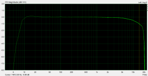
I have a question on frequency response of the Kegger/Blueglow KT88 design which I've built. It kind of seems to roll-off quite early at the high end and by 15kHz it is already 1dB down (the testing software I've used ends at 20kHz). Probably not the end of the world but just curious if this might be the fault of the output transformers. Could you suggest some (hopefully not so complicated) testing procedure how to confirm/eliminate OPTs impact on the FR I see? I am new to DIY tube amps so hope my question makes sense.. Thanks
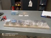
Something the thrify DIYer should know is the wonderful source of parts that are Onkyo/Integra AV receivers.
It is fairly well established that Onkyo/Integra home theatre recievers from the late 2000's and mid 2010's have a well known issue with their HDMI boards that causes them to fault and are expensive to fix.
At least in New Zealand, these end up on our local version of Ebay for cheap, often less than $20. I've been collecting these for a few years now as they are so common. I see several every month. I imagine in larger markets there would be even more.
The best thing about these is their power transformers and heatsinks.
They typically have both 120v/230v primaries and a whole host of secondaries usefull to the DIYer.
Depending on the model, they range from 300w to 900w.
The 600ish watt models typically have secondaries that look like this:
I especially like the 21-0-21v taps as these are quite usefull for chip amps etc, I imagine various lower power class A amps as well (which I haven't gotten around to yet)
The 300w models typically have secondaries like this:
Some of the higher power models have even higher voltage on the B+.
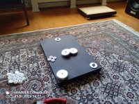
They also have good looking heatsinks:
This is the most typical kind found in the 300-600w models. Some are larger.
These weigh about 900g and measure:
289mm x 94mm x 50mm.
I estimate their dissipation at something like 0.5C/W
I imagine that 2 could be stacked on top of one another with some aluminium plate used as a heat spreader to make a larger heatsink appropriate for higher power designs. Something I intend to try in the future.
The largest heatsink I have found so far was from a TX-SR602 which was 130mm tall compared to the usual 94mm.
They also have some other good stuff on board.
Panasonic ALA2F24, 3A125V relays for the outputs
Typically Nichicon LS or LQ series filter capacitors from 6200uF to 15000uF on the higher end models
Toshiba 2SA1941/2SC5198 100W outputs on most models, Sometimes the 120w 2SA1942/2SC5242 on the higher power models.
decent bridge rectifiers
good heatsinks for rectifiers/regulators
JRC 79xx/78xx regulators
2SA1930/2SC5171 driver transistors
All in all, if one can get them cheap they are very good value.
The power transformers alone are probably worth something like NZD200 for something with equivalent VA from Mouser/Farnel et al.
At least in New Zealand, heatsinks are hard to come by so these are an absolute gold mine.
I was more active several years back around subjects such as the Tang Band W6-2313, along with BMR speakers (such as those from Cotswold Sound Systems). Since then life has been in the way and I've built up a substantial backlog of projects I wanted to undertake but simply did not have the time or headspace to pursue. The catalog of items waiting to be used include three sets of Hypex Fusion Amps, several pairs of the Dayton 10" reference woofers, pairs of both Epique subs (with 4 of each passive radiator), two pairs of W6-2313s from Tang Band, 40 CSS 2.5" BMRs, Epique AMT tweeters...the list goes on.
Like I said, substantial (I'm sure plenty of you have more parts hanging out of course)
However, over the last month a lot of those blockers have finally eased and I was able to get back to it. The main issue was that instead of designing, I needed to Just. Build. Something. So I snagged a pair of Parts Express 1.15 cubic foot knock down cabinets as a starting point, broke out a pair of the TB W6's and my Epique 7" drivers, spun up the CNC for some extra parts and slapped them into a cabinet. My goal was to take the excellent Tang Band coax drivers, pair them with a great sub, and integrate amplification into them to create a solid all-in-one build.
I call them the Copper Dragons: The top is a Tang Band W6-2313 with the highs crossed over at 2500hz, tweeter inverted with a 0.63ms delay (based on an earlier build). The Epiques are crossed at 250hz, with the voice coils run in series (correction from parallel) for an 8ohm load. Amplification is done via a Hypex FA253 on the back with an isolated internal enclosure. On the top is a Hypex OLED display (very much worth adding to the build).
Listening Impressions:
My wife and daughter have also really enjoyed music on them - even asking to play tunes together more often and pointing out things we couldn't catch on our old system (a pair of Amiga HT kits I build about six years ago)
The W6-2313 is frankly one of my favorite drivers ever. The imaging is absurdly sharp, they're very easy to listen to for long periods, and bring out details in music that you would miss anywhere else.
Bass is solid overall from the Epiques. They have really great punch and detail (for example: you get way more of the details from the bass guitar when listening to Group Four by Massive Attack)
However, the Epique woofers are held back by their limited cabinet size of 0.62 cubic feet. I didn't plan too much and just went with making them (otherwise I would over think it), which really holds them back for extension and SPL.
I love, love, love the Hypex amps though. They have been excellent performers so far outside of a few hiccups at the start. At this point I'm just running Toslink directly from my LG OLED TV into the right channel, and SPDIF from my iPad (through an adapter) for music. I'm now very glad I have two other pairs of Fusion Amps to work with on other builds.
I've tested the crossover and EQ quite a lot to get them into a good place. Right now they're very nice to listen to, handle home theater quite well (Oppenheimer was a great one), and I'm happy for now. So what's next?
I'm considering building a new pair of cabinets with ~1 cubic foot internal volume and a 31" long 1.85x6.5" slot vent instead of PRs to get a much better overall response.
Another thought is swapping the Epique drivers out for something else, such as an 8" Ultimax (also in new cabinets). The Coax drivers also reach fairly well into the ~100-200hz range in their enclosures, so a more dedicated sub might be a better option.
I also might just build new cabinets and keep the PRs if I can find a volume that really compares to the vented alignment.
Hello all, I had a question about converting the output on this schematic to be compatible with 8 ohms speakers. The description mentions 32R to 600R range with 100R load being optimum
I'm 65 and love great audio inside and outside. I have a 911 and had that professionally installed with new Helix AMP/DSP Mk2 and Focal Speakers. I just bought a USED 2022 Honda Pilot Touring model with upgraded OEM Stereo 8 channel 365 watts - ya right - which is supposedly better that lower builds of this years Pilots.
Anyway, I 've updated all 8 speakers with NEW Focal Speakers and Subwoofer. It's amazing how much better it already sounds. The Touring addition of the Pilot has a 365 watt amp, if I remember right, and 8 speakers/SUB. I bought an OEM eBay amp (Panasonic builds for Honda) with pigtails and internal connection to build my own T connector.
The plan is to take the output of OEM Head-unit (HU) amp and use that as input to Helix 8 Channel DSP/AMPs Mk2 High-level Input. Hook up the speakers via the other side of the T connector from output of Helix. I've been reading the manual and don't want to fork this up.
It talks about setting up the internal jumpers properly when using High-Level inputs and I want you guys that are more familiar with all the latest gear for expert help on doing that. Remember, I'm from the days of 8 track and cassette. I believe I want to set the Helix internal Jumpers on the "A" series jumpers so I can set and control all 8 Focal speakers/SUB with the Helix software??? Is that correct??? Anything else I missed?
If you have any other input tips for my build, I'm all ears. Much appreciate any help!
I just signed up at diy audio hoping to find some help.
Back in late 2020 I replaced all the electrolytic capacitors of my SRM-006t and added CCS to it. Later I went for ECC99 tubes, following the advices given in this thread and the german blog that somebody posted a link to some pages back. Everything went well and sounded brilliant with my lambdas.
This year I traded my modded 006t for a used SRM-007t, adjusted the input voltage and replaced all electrolytic capacitors. A few months later I successfully performed the rather comprehensive work for it to take 6S4A tubes. Based on my experience with CCS, I decided to add this feature to my 007t as well. That's where I'm struggling currently.
Of course, this time I adjusted the outputs to 8.0mA each. For some reason I keep frying the fets in my CCS. Parts were purchased from Mouser, I would consider them genuine. First I though this was a temperature issue, but even when using massive heat sinks on the 10M90S, both fets (10M90S and DN2540) keep failing, from time to time. By failing I mean, that one or both fets in each cascade seem to lose the ability to restrict the current flow, leading to way too high CCS output currents up to 20mA (instead of 8 what each CCS is being adjusted to). Of course, the power supply can't provide that amount of current without B+ dropping. My current working hypothesis is that the gates of one or both fets of each CCS get damaged, either during power-up of the amp or after switching power off. 10M90S are hard to find, and I'm in urgent need of a solution for this so that I don't keep frying them. Unfortunately, I'm not able to tell which fet "goes south" first in case of a failure.
I was given the advice to use Dale resistors which I did, but didn't help solve the issue.
Does anybody have an idea about how to fix this? Any help is highly appreciated.
I just received a Rega Apollo (wide, early version) that I knew had problems. I played it tonight and it suddenly stopped as I was told it would. I started it up again and the problem did not reoccur (and has not in daily use for two weeks) and it sounded fantastic. I assume I will replace the transport ( SF-P101N) which is readily available for very low cost. The ribbon cable (which apparently also can be the source of problems) is not so easy. I am not very familiar with these and could use some help finding or specifying. I was hesitant to remove the existing cable but I opened the mechanism enough to read "SUMITOMO-H AWM 2896 80C VW-1" Since I did not remove it I do not know the length (8"? 200mm, guessing with 16 contacts)
Has anyone replaced this mechanism and can help me sourcing the cable?
I have an Arcam Delta Blackbox 1 Dac, the Dac have only 1 coaxial digital input.
I would like to modify the Dac digital input section with a DIR9001 based input board which have both coaxial and optical inputs and I2S output.
My question is, can I connect the DIR9001 Data and LRCK or BCLK outputs directly to ARCAM's IC304 custom chip inputs (DATA and CLOCK) ?
or I need to omit IC304 and connect it directly to the digital filter inputs (or going NOS and connect the I2S directly to the TDA1541?
Hi
While I have loads of old speakerunits, I was wondering if a separate thread would be an option,
Using DATS3 , I found out that a lot of them, mostly domes, but also a few paper cone midwoofers were out of spec, I started by taking the domes apart, a lot of them had old ferrofluid in them, that stuck like glue to the coils, removing the fluid, cured most of the wrong specs....but what to do, fill the gaps with new ferrofluid, what type, where to buy, etc.
If possible a bit of knowledge on this subject would be nice, maybe there are more people interested in this.
Cheers, Tom.
Back in the day, I was very friendly with Dick Shahinian. I tried (this was before I was writing for TAS or Stereophile, please note) to see if I could get a company in Rhode Island interested in making some cabinets for him, in that they were early adapters of CNC woodworking. Their clients for whom they made hotel and restaurant fixtures included Disney, Inc. However, they were not interested in following through. (There was probably not much per-unit profit in a small loudspeaker.)
Anyway, just for the sake of Nostalgia, and before I recycle them (they are photocopies and not originals) here are the shop drawings for the Super Elf cabinet, circa 1992. One potential source of confusion is that the Side drawing has nestled within it an out-of-scale Top-Down view of DIck's preferred "Diamond Brace," which is crossed out. It therefore seems that he wanted the Rhode Island firm to quote on a "Conventional" Brace.
Audio was so vibrant back then!
john
PS: If anyone wants the large files of the scans, please message me and provide your email address.
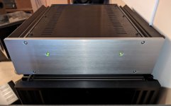
Am working with a family member to diagnose and repair their treasured ML-335 which an uncooperative authorized ML repair center performed repair work on and sadly still has issue which the dealer is unwilling to diagnose and repair without an additional fee. He can’t afford another multi thousand dollar fee , so I’d like to, help, but before I get in too deep into D&R I’d like to ask if anyone in the community would be able to please share the service manual or any circuit diagrams?
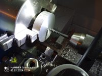
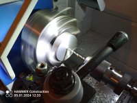
Been working on this "F7 inspired" clone, which has been a very fruitful adventure. Just as I was finished biasing the amp, the GND on one of the power rails jumped out and shorted to the V- on the same (this is at the PSU board) as I saw it happen I quickly I was able to power down the amp before "anything" happened. But as we know sometimes things happen in instants.
Before you scold me, I know, shouldve done a better job of soldering and confirming, which I'll you I thought I did, but alas, we've all been there I suspect.
After the frustration and panic subisded, and I got back to and and carefully checked and powered up the amp again after repairing the loose wire. All checked out and it plays normally.
Now, I've hooked up to a signal generator and an oscilloscope. The Oscilloscope was connected to a 8R 25W resistor meanwhile the signal gen is run directly to the RCA inputs. I am running a 1000HZ signal @5V to the amp, and I am hearing a high pitched whine coming from the amp somewhere. If I raise the frequency, so does the pitch go up.
Admittedly, I didnt get to this step before my incident, and this is my first rodeo with the oscilloscope and generator in this way. Inevitably I wonder if its related to my previous mishap. My intention was to check that the response was the same on both channels, though for all I know I am going about it all wrong. This is prior to hooking up to a analyzer to run THD etc.
All in all, looking for the best way to proceed - big DOH moment, and sadly, just before crossing the finishing line.
Hello,
Currenly working on my Hifonics BXI6000d.
Maybe someone can helpme with this.
Someone was working on this pcb, and i think he soldered the wires from the feedback resistor on the wrong spot.
Looked at many pics of the two wires. But can't see clearly where its connected to..
Is it connected on both rails on the Drain (center pin)
Hello everyone,
I just acquired a Yamaha M-50 stuck in protection mode. Here is what I have found so far. No burnt components on all boards.
Tested DC Voltage on the output transistors on both sides of the board per the service manual and seem to test fine.I plan on
removing output transistors from the unit just to verify that they are functional. Has anyone in this group had to pleasure of working
on one of these units?
Thanks,
Audi2014
I have a lot of pre and power valves that I want to sell and sell with integrity, ergo I need to get them reliably tested. Most are NOS and a few have been used for not many hours. I live in the north of the Tarn, about 30K from the Aveyron. Does anyone live reasonably close that has expertise and good testing equipment?
I have Round Plate 6F8G - Tung Sol/National Union/Ken Rad etc. Russian Melz 1578/ Svetlana KT88/6550/EL34/French Mazda mil spec 12AX7 and more.
I while I wait for my LCR meter to come, I read about how you can test capactiors basic with a DMM. One way is the resistance measurement which I read, if you set to ohm setting and then connect the leads, it should failry quickly read a resistance and get to OL.
I have a 10uF 400v capacitor and I did this, the DMM ran quickly throught he KOhm but then progressed to the MOhm setting and just slowly rises, and takes about 2 min to get to OL.
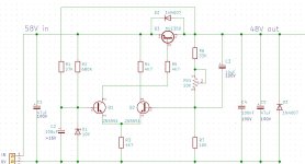
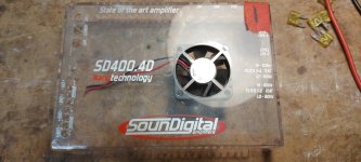
This SounDigital SD400.4 is a 4ch, yet it uses a single TAS5630 chip? The chip says it will do either 600W x 1 @ 2Ohm; 300W x 2 @ 4Ohm. Are they somehow splitting the power into 4 channels? Orr... I have never really looked much into their design... just want to make sure I'm ordering the right chip. Definitely going to have to try and figure out what they have going on in this amp if that is the right chip, lol.
Looks like the only ones available are the TAS5630BPHD version. Slightly less output bridged.
Edit: I'll post a couple pictures once my post is approved...
Hi
I'm assembling phono preamp based on op amps and stumbled upon weird situation (maybe just for me).
I'm using ne5534 for tests, non inverted input, ground resistor 200Ohm, feedback resistor 1k or 10k (switching gain, putting 1k in parallel to 10k).
And I was confused that with 1k (lower gain) there is a lot of audible noise (hiss, white noise etc) and with 10k it disappears!
Is that normal or is it faulty opamp (or for ne5534 is it common) or resistor or what?
I seem to remember an article presenting how to run a 3-way speaker with two amps per channel, without a passive crossover per se.
The principle was that a low pass was added to the bass driver at leatst 1 octave above its intended crossover point, and similarly a high pass on the tweeter (and I'd assume a LPAD to bring its effective sensitivity down) below its crossover point - and then the two could be run on a single amp channel with a suitable active crossover, with the trebble and sub signals mixed together..
Does anyone know where I might review discussion/article on this?
I had in mind there was a patent.
I do have multichannel capability but I also have a spare 2x4HD and a couple or stereo power amps.
My first post here. I built the Gabster D6 Streamer/Dac and have an issue where the beginning of songs are clipped off as the music is playing from a playlist in either Spotify connect or Tidal connect.
Anyone know how to solve this?
Everything is connected and configured according to the documentation available at Ian Canada.
The music is coming from the Raspberry Pi 3+ in the stack.
The Streamer/Dac is a significant upgrade from my Bluesound node.
(I will be building this into a case once the screen arrives.)
I bought this Kenwood KD1600 TT, appeared new in original packing. Turns out it was used and the belt had long disintegrated. So I try the belt from my Phillips TT. Using a strobe, motor 1800 RPM syncs to line and when I put the Phillips belt on, platter spins steady in sync to line, using my Roberts strobe disc.
So I buy "the right belt" off an ebay seller, which is claimed to cover a range of these Kenwood models. Bada-bing, right? The belt is pretty much the same length as the Phillips belt, but only 1/2 the width if that. Platter doesnt run to speed.
There's no speed adjust on this particular unit. The motor can take quite a load from my finger, before is loses sync to line. The platter spins quite freely. The "pulley" post can move up/down some on the motor shaft, but trying different positions gives the same result. Putting it back pushed all the way onto the shaft and using the Phillips belt again, the platter runs at speed. Unfortunately the Phillips belt width scrapes on the speed changer boss end, so it's a smidge too wide.
Question #1, is it possible to fix? It's impractical to go through ordering a myriad of belts until I find just the right one. Cost prohibitive.
Question #2, is it fair to return the belt to the seller, claiming with it the TT doesnt run at speed, while with one I happened to have lying around it does?
I thought it would be easy. Instead, the conglomeration of simple mechanical components behaves like it's haunted.
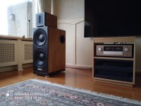
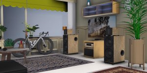
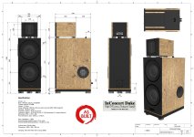
This is THE smaller, great Powerful brother of the previously successfully built Tangen's InConcert Miles.
A wonderfully robust, solid and modularly designed sleek combination.
The difference is that it has 12" basses and the same plate tweeter, but without the horn.
This is effortless, very dynamic, powerful and tight.
An unprecedented Superior High Efficiency with a Very Broad and In-Depth Reach!....
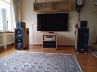
A fantastic complete concert hall and live recording in your listening room!
This really is a great, powerful display with everything you need!
Listening to this combination will never tire you, rather fascinate you!
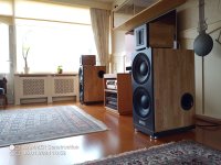
Equipped with high-quality, beautiful professional drivers from Beyma.
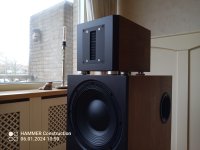
No less than 4x 12 inch 12P1000Nd bass to caress your living room and ears with the unprecedented quiet and deeply controlled, tight bass.
This is generated by the large surface area in combination with the small displacement of the cones, which also results in minimal deformation.
In combination with the great Ribbon Tweeter, the TPL-150B from Beyma for ear-pleasing and detailed highs.
Everything superior, very beautifully filtered and in proportion!
Superior drivers positioned in very well built and designed housings in accordance with the original design, but in their own separate jacket.
A great combination to completely fill your listening room with the most beautiful sounds and with the highest efficiency.
This combination cannot be beaten in terms of control with the least power and the high efficiency that is reproduced.
Truly everything comes and goes with the minimum of ease.
A superior PA combination with HIFI playback in your listening room!
Also very ideal for a tube enthusiast!
Built with great care and very solidly.
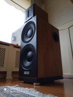
Very beautiful Beyma 12P1000Nd with its beautiful large dust cover and ribbed cone, a feast for the eyes.
The TPL150B too, of course again, just like with the InConcert Miles, in a separate room to completely exclude any unwanted influences from the bass room.
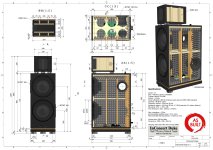
It is a 2.5-way construction, with the upper bass playing the full tones (unfiltered) while the lower bass has a partial filter (LP).
Also plays very well, very powerful and dynamic.
The depth and efficiency of the bass is comparable to that of the Miles.
This is done by increasing the capacity from 77 liters gross to 100 liters net and ideally tuning the best ports, 2x Jetset 100.
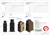
The Duke plate tweeter works in slightly better working conditions up to 1200 Hz than that of the Miles (up to 900 Hz).
This Duke will have a great game with the Miles.
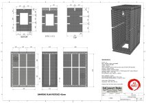
Cabinets are solidly made in black and clear HD MDF in combination with solid oak.
Damping entirely 42mm Pritex except the baffle in combination with 8mm self-adhesive felt.
Specifications:
Drivers: 3x
System: 2.5 way
Power withstand: 1800 W continuous pink noise (ref AES2-1984 standard)
Sensitivity: 98 dB for 2.83V
Frequency response: 30 Hz to 25 kHz
Frequency response: 40 Hz to 20 kHz +/-2 dB (measured at 2 meters distance)
BR tuning: 47Hz -> 47Hz -3dB
Port dimensions (2x): diam. 100mm, L=140mm
Nom. impedance: 4 ohms
Recommended amplifier power: 1W or more.
Recommended listening distance: 2 meters or more.
Volume bass: 100 liters Net
Dimensions: 1090 x 350 x 550 mm
If you are seriously interested, an extensive listening session is possible by appointment.
Can be listened to in combination with the node 2i & Accuphase E-380 or your own source.
I seem to remember seeing a variation of BA-3 with balanced input (two JFet pairs and one Mosfet pair ouput), but can not find it anywhere. Can someone please point me in the right direction.
Hi everyone,
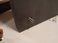
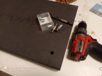
I Thought I should share, it might not be very useful but I’m sure someone had the same idea and it could save them the butchering.
These days I'm entertaining the idea to build a bluetooth portable speaker, more for the fun than the need.
With many ideas from micro to a big one I'm still undecided.
So that's why I got a pair of these little vappeby yesterday, pretty cheap at 10 euros.
Since they support TWS I wanted to check.
They're pretty weak in SPL no surprise, I expected a little more clarity but they went for the boomy effect.
I feel like there's a sort of membrane in front of the speaker for waterproofing, so why not removing it and see the result?
It turned out I wasn't able to open them without butchering them, it's all glued of course.
And the baffle/membrane/driver are all glued, I don't think I could separate them.
Anyway it sounds a little better opened, less boomy, better for voices/podcast at least, but is still weak.
I might just use them in my work truck that doesn't have any audio system, better than the phone alone at least.
Here are the parts I found (I'm not an expert at all):
Maybe I'll reuse them as preamps in my project, in case I don't pick an amp board with BLE and TWS support.
Or just quickly build another enclosure with a more sensitive driver, 3W are not that bad.
I also got the big vappeby for 50 eur, sort of eneby gen3 in 20x20.
Much better sound of course but still a little boomy, especially on a table (I couldn't find the bass/treble settings that existed on the eneby).
It can be battery powered as an option and now supports TWS, so PSU and/or 14.4v battery, volume control, ble and aux in, 2ch amp with crossover, with probably some eq/dsp applied though.
Very cool little package for a beginner diyer like me:
Based on what I found on youtube the main board is new and smaller than gen2, so easier to integrate in another enclosure:
I'll update with more pics next time I re-open it, I will also measure the crossover point and maybe the power at the driver, to help deciding if it worths being re-used/converted with the spares I have around.
Has anyone used one of the cheap Chinese "VU" meter boards + meters in any of their amp builds, if so did they work ok without modification? Also have such boards created problems with distortion? Lastly if meter driving circuits in general create unwanted THD & N can anything be done to alleviate it?
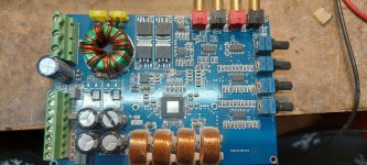
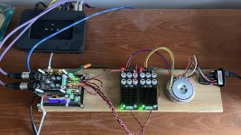
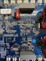
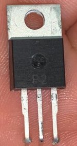
I'm working on this Chinese Soundigital replica. The main difference is the output drivers. Instead of using a zxgd3005 like the original SD or other chinese replicas use, it uses 4 buffer transistors. This changes the way the gate of the power transistors is handled. I have used the usual references used in original SD and Chinese replicas, but without successful results. The amplifier turns on, but with a minimum load of 100w it goes into protection. The power transistors of this amplifier are marked as P2 and the packaging is INFINEON OPTIMOS 3 or OPTIMOS 5. It has a gate resistance of 33ohm originally. 170khz oscillation and 140v. Has anyone worked on these chinese SD plates and knows the original P2 reference? Or how can I calculate the gate resistance to modify the gate resistance so that the power mosfets work properly?
Pair completed boards from Hugh Dean from Aspen audio.SOLD AS IS!!!The biards are good in function,you must provide your own heatsinks and psu becose on board there are no more diodes or capacitors,also the red jantzen input caps are not more on boards and the nichicon kg also not.The price is becose of this inly 50 euro for bouth boards plus shipping inside EU that will be abouth 15-25 euro registered.Payment paypal by friends.
I'm looking into building either one or two 18" subs for home theater application, but will likely also serve double duty as subs for inside my Sprinter van on occasion.
I've never had any sub in home or car more than 12", and the goal is to get some really deep bass that can be "felt", yet still maintain a fair level of SQL.
I'd like the boxes to be not obnoxiously large or heavy, so probably somewhere between 4-8 cu.ft. for each driver.
So, for these drivers and probably any other inexpensive 18" driver (or larger) I am looking at sealed boxes.
Crown XLS 2502 is available to power the HT, and SoundQubed Q1-1200.2 available as power for van application.
I saw UM 18 for $288 recently which seemed like a great deal, but then stumbled upon the SI HT-18's in forum discussions and they seem very promising for $200.
Does anybody have direct experience with both of these in sealed box applications in the size range I am looking to build? It would be great to have an "apples-to-apples" comparison is anybody had experimented with each of these in identical boxes with identical power. I know this kind of thing can be modeled in software, but I am more interested in getting some feedback from an actual person experiencing them first-hand.
For the price of 2 UM, I could get 3 SI, but since I wouldn't use 3 drivers I guess the question becomes are the UM worth $600 vs $400 for the SI's?
Also, if it turned out that only one would up in my house and only one in the van, then would the SI handle enough power and provide similar output as the UM?
I picked up a BAT VK-5i preamp that has a hum problem in the left channel. I found a schematic of the amplification circuitry, but I don't have any info on the input selection, volume control, power supply, etc. I haven't started digging into the potential problem(s) yet, but I'd appreciate any information anyone might have on documentation, similar problems, etc.
The preamp was sent in for service to BAT a few months ago and received new tubes and some cap replacements. But it started humming again within a month or so of getting it back. The previous owner decided it wasn't worth continuing to try to fix it, so he sold it to me as is.
I have a new DAC and Amp on the way. Which is High quality for me; Emotiva XDA-3-DAC-balanced, Emotiva XPA-1 balanced Monoblock's.
I am currently using Amazon Music, Firestick, and an older Marantz receiver SR7002, and some fairly decent Towers with good tweeters Carnegie-CST-1.
I understand recently now, that ROON and such does not accept Amazon music.
I enjoy having time with each stage of improvements.
As the next stage of listening;
It looks like initially; I will be feeding Amazon > the Marantz Receiver > digital coax to the new coming balanced DAC > balanced amps.
For one of the next stages, would IanCanada's devices be able to receive HDMI feed from the Amazon firestick? or am I missing the point?
Perhaps the Ian devices accept ethernet only? and will then need ROON and the other things that come with that?
I currently have an NVIDIA shield still in the box that I'm debating to return. I understand the NVIDIA shield $200, will accept Amazon music, and feed digital to the new coming DAC.
Hi every one!
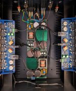
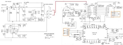
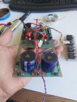
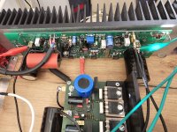
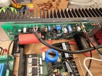
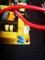
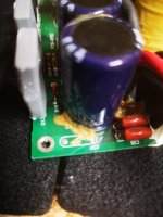
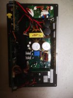
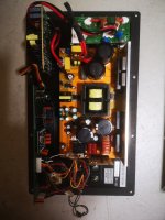
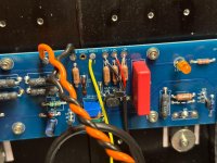
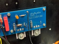
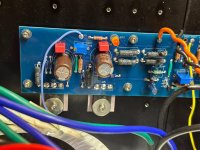
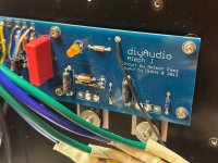
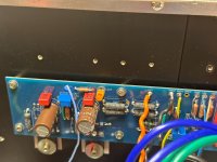
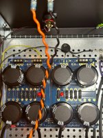
I have a subwoofer Class D plateamplifier in a Audio Physics Rhea 2. Original amp is dead and i have replaced it with one Similar but not excatly same. Ut Works fine, except for it making some hum at speaker output. Could this be cause by the blue components in picture? The original amp do not have them and was complete ly quiet. Could i Just remove them for a try out?
I hope someone can offer advice to an inexperienced DiY audio tech.
I've recently come to own a Denon AU-320 step-up transformer. When connected to my phono pre-amp the signal will pass through successfully. That is the Pre-amp is set to its usual MC setting and the signal from my tone-arm passes through the AU-320 to the pre-amp and on down the line as usual. This seems to indicate the wiring of the left and right channels, from input to output are correct.
When I switch the Au-320 to use the transformers (and my pre-amp to MM) - either in 3ohm or 40omh settings, the left channel of audio drops out.
Any ideas what might cause this?
I've opened it up and removed the transformer, cleaned what I can with deoxit. The wiring looks original and I don't see any breaks... but if there were a break... where might it be to impact both 3ohm or 40omh settings and not the signal passthrough?
Does anyone know of a circuit that can take the vertical or horizontal sync pulse from a VGA signal and generate a sawtooth waveform?
I've got a project where I am wanting to display a VGA signal on a Tektronix XY display and want to have at least two resolutions.
720 X 576 for 5:4 displays and 800 X 600 for 4:3 displays.
The idea is I want the sawtooth waveforms to automatically switch frequencies if possible.
I could even use a switch to select two frequencies if need be, however I need to know what those frequencies need to be.
I've got a Leitch FR-684 video distribution frame that can hold 10 cards and two have daughter boards that plug in and I was going to use those two for the sawtooth generation and a third for the video as the output from the card will have the proper levels so that the displayed image looks its best.
I'm owning a NewClassD Neutrino crystal oscillator generating 12.288 MHz. Due to a forced change in my project (system failure that cannot be repaired at reasonable cost) I would now need the oscillator to generate 24.576 MHz. This should be possible by changing the crystal, so I tried to find out which 12.288 MHz crystal is used on the board. Unfortunately NewClassD seems to have disappeared, so I cannot ask them...
The marking just sais "122 ADIF" which I was sadly unable to find on the web. And so I'm asking for help here to identify the crystal used and to find out with which (ideally compatible) 24.576 MHz part I could replace it.
Thanks so much for any help you can provide!
Regards,
Winfried
Is it worth it -- even a little bit -- to upgrade any of the TL072 opamps to something more snazzy? Asking mostly to learn why not, but if there is even a small benefit, I guess even great opamps are like $20. I would consider doing it on one mic pre. I asked this same question about a much worse mixer, but this one is already good. Any thoughts?
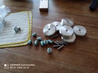
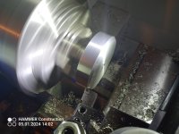
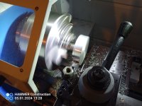
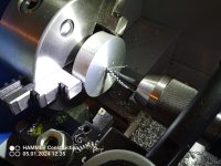
A couple of months ago I picked up a pair of over-priced derelict Dynaco MK-III tube amps.
They didn't have any rectifiers or power tubes, and one of them had a pretty well over-heated choke which had kakked its sealing wax all over the inside of the bottom cover.
So rather than trying to get them functional I decided to simply strip them down and start over. The power and output transformers were good, and that's really all I needed.
The chassis are both fairly pitted, and there isn't much that can be done about that, and a liberal application of metal polish didn't erase the pits, but these are not meant to be show pieces, they're meant to be working examples in my primary system.
My plan is as follows:
Modify the input circuit to get rid of the admittedly not-that-good-sounding 6AN8 input/phase splitter tube.
I settled on an elegant input circuit designed by Kara Chaffee and written up in an article in AudioXPress, March 2001.
It uses 1/2 of a 12AT7 (a tube I really like the sound of) as the input stage and a 6CG7 dual triode as a long-tailed pair phase splitter. It also has a clever variable feedback circuit.
Retain the tube rectification, which I think is important.
Remove the selenium stack and replace it with a modern diode.
Remove the can capacitor and replace it with a modern replacement circuit - I chose the design from Sheldon Stokes's "SDS" Cap Board having had positive experiences with it on previous Stereo-70 restorations.
Install modern ceramic tube sockets, and replace all the ancillaries - switch, speaker terminals, input jack, power cord - with new modern equivalents.
Remove the redundant wiring for powering a partnering preamp from the front panel socket but keep that socket for bias measurement.
So step 1 is done - strip the chassis, remove all the tube sockets. This particular amp was factory built, and the sockets were riveted, so those had to be drilled out.
(photos of the "before" are not the amp in question - this clearly was not factory built, but is in very similar condition to its mate which is the stripped chassis)
This is spurred by post #48 at https://www.audiosciencereview.com/forum/index.php?threads/human-speakers-81-dk-review.50915/page-3
"The woofer is supposed to naturally roll off ...in order to gentle cross with the tweeter that uses a single capacitor as the whole filter crossover" to which I replied "Once upon a time, I made something like that. And recall some drivers like that. Nowadays, I've been looking at a lot of different types and sizes of woofers and NADA. Nothing seems to roll off smoothly any more."
?!?
Am I blind? Missing something? Everything seems to have resonances on the top end and gyrations in frequency response...
Hello, i have a small sub and i connected with audio eng A1 the thing is i am note sure i can tell the difference , the small sub is the yamaha https://www.ebay.ca/itm/295322537940
Is any reall difference between the 2 in music, can someone feel the difference ?
Objective: check the square wave output of 10w amp design.
I've copied from Mike Engelhardt quick start video which uses "pulse 0 1 0 1u 1u .5m 1m" expression
I also include:
.tran 3
.plot V(out)
.four 1K V(out)
Result-
Fatal error: This .four requires 0.001 second of time but only 0 second was simulate
1) I'm wondering if I'm misinterpreting the QSpice quick start guide!
2) I placed a 6ohm resister load to OUT - should I delete this? Without shows a broken square wave of sorts!
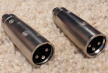
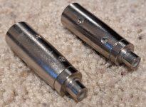
Hi the ones on ebay like this https://www.ebay.co.uk/itm/284655593945 apols about the spam but at least known.
I have a question as the ouputs have a positive / negative and a ground?
How do you wire the speakers up IE positive/negative of the speaker cable should go to which when used a stereo amp?
Is it so if you where going to use it in bridge mode, it has x3 connectors for each channel output?
Edit apols a rooted out my better reading specs.
Its L+/L- V+/Gnd R-/R+ it was my eyes, apols.
I've been tinkering with audio gear mods for years. My current modding project (a Sony QS-series SACD player) has two electrolytics in the signal path, one after the DAC I/U-converter stage, and one after the differential opamp stage. I started thinking on the possibility to remove the signal path electrolytics altogether.
So, how much DC offset is too much, so that you would not remove the signal path electrolytic capacitors? 1 mV or what?
I've been building this 300B amp for the past year or so. I want to use regulated DC for the filaments. I have done the math on linear regulators and found that I will end up dissipating more power in the filament regulators under worst case conditions than the amp will deliver to the speakers. I find that ridiculous... Needless to say, I started dabbling in switchmode regulators. They actually work really well...
So I was thinking. Wouldn't it be nice with a universal switchmode filament regulator? Universal, as in programmable by a resistor change to different output voltages. I'm thinking to support 2.5 V for 2A3 and the like, 4.1 V for the Russian tubes, 5.0 V for 300B, 6.3 V for just about everything, and 12.6 V for the tubes with series filaments.
Are there any other common filament voltages that should be supported?
I'm thinking to use an LM3102 as it allows me to hit the above voltages without too much fuzz. Its max output current is 2.5 A (just enough for a 2A3 I think). It's also in a package that's hand-solderable by most humans.
I'm throwing this out there to get the process started and to gauge the level of interest in such a project.
Since I'm a glutton for punishment, and I don't want to leave anyone out:
This is an ACA Mini PCB with artwork designed by Mark Johnson following the Nelson Pass circuit. It is very close to the artwork released by Nelson Pass for the boards which were given to some lucky participants of the Burning Amp Festival. Mark was gracious enough to produce a number of his boards and give them away: I was one of those recipients. I have built the amp using this "Almost Clone" board and it works and sounds fantastic. It was suggested that a group buy for this "Almost Clone" board get started...so here we are.
This group buy will run with the quantity limited to 20, and the time limited to two weeks, whichever comes first. This thread is for those OUTSIDE OF THE CONTINENTAL U.S. ONLY. If you live within the CONTINENTAL US please post HERE.
Photo's of a completed amp can be viewed in the ACA Mini thread #462
Of course you will be using the Nelson Pass article for a description of the circuit, build guide, and biasing instructions found at the beginning of the ACA Mini thread #1
Cost of the board will be $12 with you paying the actual shipping cost from my address in Hudsonville, Michigan 49426 USA. Please check the actual shipping cost before adding your name to the list.
To purchase a board simply copy the post with the current list of names, add your name and quantity, update the total, and paste to new post.
This Group Buy will end on January 22, 2022 at 12:00pm EST
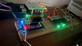
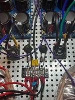
I am just putting the finishing touches on a Dual PSU Aleph J. It is my second Firstwatt Clone build, the first being an F6 that went off without incident and has been running great for about 2 years now. I have following the build guide, and the same procedure as the first time, but this time around when I powered up the amp for the first time, LED 2 on one of the amp boards is blinking. The other amp board seems to be functioning normally. I have attached images to show how everything is currently wired up, please excuse the mess as I will be tidying everything up once it's all functioning and biased.
I have inspected all the components to the best of my ability and everything seems to be oriented correctly. I couldn't find any cold solders either. I tested both PSUs prior to assembly, and found a consistent reading of 24.6VDC and -24.6VDC respectively on both PSU boards. My lightbulb tester also behaves normally when the amp boards are disconnected, but the lightbulb dips and then goes full bright when one or both amp boards are connected.
Does anyone have any ides of what it could be? Am I missing something super obvious because I have been looking at the amp for too long today? Any assistance would be greatly appreciated as I am totally stumped.
Thanks so much and feel free to ask any follow up questions. I will keep an eye on the thread and respond asap.
Hi guys, have any of you used this DSP? can you help me with room correction settings, because I tried to follow something like this video, but after activating "AutoQ and after L+R... nothing happens because it goes back. Maybe it has incorrect settings?
Hi, I have a pair of Sun Audio SV-300B mk2 amps which I guess are around 25 years old now.
They sound clear and detailed, but have a slighty forced edginess to the sound at times which I would like to improve on.
Most of the caps fitted are the original electrolytics and I'm interested to see if I can get an improvement in the sound by changing them all out for MKP film caps, so no electrolytics anywhere.
The general advice has always seemed to be "sure, that would be nice, but they will be huge and expensive" but it seems like that is not necessarily the case any more. Plus, in a simple amp design with mostly point to point wiring, there is some room to be creative with placement.
So I have got myself a load of Kemet C4AQ caps as they come in the specs I want at reasonable sizes/prices and they seem to be well regarded here.
I am now planning out how best to approach this.
I don't want to entirely bastardise these lovely amps, but it seems like I can probably do this in such a way as they look identical externally and if it's not a success, this change can always be reversed if I want.
I'm interested in any general advice on the plan, whether there's any considerations I may have missed, and any practical tips for working with these type of caps, like how others have mounted them. I may make some hold-down straps, or I'm wondering whether sticky pads or glue onto the flat chassis plus the soldered connection could be mechanically sufficient for most of them. I'd like to understand whether all 4 legs should be connected or can I snip/bend 2 of them out the way. That kind of thing.
here's the schematic
here's the existing layout internally
47uf+47uf cap from the CLC and the 2 x 100uf 300B cathode resistors poke out the chassis at the top, but they take up little room internally so can probably stay in place (disconnected)
Here's a very rough test-fit of how the C4AQ caps could be placed (bottom left ones will fit further in with the electrolytics removed). It'll be tight in places, but it looks totally practical to get them where I want.
I feel I should assess the 47uf + 47uf in the B+ CLC whilst I do this as the Power Transformer gets quite hot in use and I wonder if that's cos 47uf is a bit large for a 5U4G input cap. So maybe that will end up being 40uf + 75uf instead. I have some different capacity options coming and plan to scope the various ripples.
The voltage ratings for the cathode bypass caps are excessive, but if they physically fit (which they do) is there any negative to that?
What do you think?
Any input gratefully received 🙂
I would like to use the parts I have for DIY PSX, I have 25v & 35v Toroidal transformers. Below is the schematic I intend to use. My questions are
25v toroid will give me 35v DC, which is less than the original transformer voltage inside the Cyrus 2, and 5v less than PSX, will it be a pointless exercise building an external power supply like this?
35v Toroid will give me 50v DC, which is 10v more than supplied by PSX, will it blow the Cyrus 2?
I used Toshiba jfet's in my pro audio product designs for over 25 years. I am now retired and I still have a large selection of the following real Toshiba JFETs..
2SK170 BL and GR sorted (Vgs using 49.9 and 22 ohm source resistors) and unsorted, many of them still in sealed bags of 200 ea.
2SK74 BL and GR sorted
2SK389 BL (pulls, tested)
2SJ109 BL (pulls, tested AND NOS in sealed bags of 200 ea)
The pulls came from older products that were going to be thown away. We pull the Toshiba JFETs off using a hot-air rework station.
These are the real thing. I purchased them 9,000 at a time (boxes of 3,000).
If any one is interested in buying some of these, let me know. I'm not interested in selling one's and two's of these parts, so please don't ask.
I am looking for an inexpensive pre-built high voltage field coil speaker power supply. I have a couple of Jensen A12's with 5 to 6k ohm coils, so I am looking for a DC supply about 300 Volts and 100 ma, adjustable voltage or current.
I can see some HP instrument supplies like the HP 6186B DC Supply and also Fisher Biotech FB 650. Since the high impedance coils require low current, I would think the HP lab supplies might work well. The Fisher Biotech supply is for electrophoresis and biology research, so there are a lot of these high voltage DC supplies available since they are used widely to induce gradients in gel beds.
Deep within other PSU discussions a poster mentioned the Fisher FB 650 was a heavy iron design and might have better quality power than other modern circuits. I am not ready to build or purchase a high fidelity PSU and would like to just start with a good quality used supply borrowed from another industry or purpose.
Can’t find anything meaningfully more powerful than the good old B&Q 1000ASP (600W @ 8 ohm). Would've thought the market would have made some progress since 2007 (power, price).
I’m looking for something on the order of a Behringer NU6000 (approx. 1,000W @8 ohm), which I have but want module format for another project.
This is for hifi (up to max 400 Hz) so no loud fan requirement.
I am in need of some additional gain (at minimum +12dB) but both the voltage is limited to 3 volts and it needs to be extremely basic (preferebly single FET) as to fit onto a 5x2cm veroboard.
The only control I need is volume.
The purpose is to boost the signal level of a passive electric bass.
A friend of mine is a HAM operator and needed to replace this tube in his transmitter. He asked if it could be used in a home stereo amp. In his application it runs 3600VDC on the plate, and around 700ma plate current. I simply don't know.
When viewing a multi page thread with my phone I cannot select to go to a random page like I can with my computer I am only allowed to either go one page or right back to the beginning of the thread (page one).Is this normal or is there a fix ?
This is an ACA Mini PCB with artwork designed by Mark Johnson following the Nelson Pass circuit. It is very close to the artwork released by Nelson Pass for the boards which were given to some lucky participants of the Burning Amp Festival. Mark was gracious enough to produce a number of his boards and give them away: I was one of those recipients. I have built the amp using this "Almost Clone" board and it works and sounds fantastic. It was suggested that a group buy for this "Almost Clone" board get started...so here we are.
This group buy will run with the quantity limited to 50, and the time limited to two weeks, whichever comes first. We will be shipping to addresses within the continental US during this first group buy. Depending of the success of this buy there may be another and the parameters may be broadened to include the rest of the world. For now I'm trying to keep this thing as simple as possible.
Photo's of a completed amp can be viewed in the ACA Mini thread #462
Of course you will be using the Nelson Pass article for a description of the circuit, build guide, and biasing instructions found at the beginning of the ACA Mini thread #1
Cost of the board will be $12 with $5 in shipping to an address within the Continental USA.
To purchase a board simply copy the post with the current list of names, add your name and quantity, update the total, and paste to new post.
This Group Buy will end on January 22, 2022 at 12:00pm EST
I came across this and thought others' might find this interesting.
It includes building a guitar amp. I didn't do it and built my own 10W amp.
I will publish the design to the appropriate diyAudio section at a later date.
How do back to back polarised electrolytics compare with bipolars?
With back to back I can reform parts that have been sitting in a draw for years, with bipolars what happens as they sit idle?
Does anyone know of on off the shelf digital hours counter or a kit to build one that can be used to count hours of operation (for an ARC REF75SE amp)? Something that easily and automatically has a running tally of hours that the amp was turned on ? Something must exist or it looks like there are several inexpensive digital counters used for lawn tractors and similar that should be able to work for this purpose?
They seem to be interesting concept which seems to be working very well for pro audio purposes, especially in applications when even coverage is important.
Live CDD15 for example, seems to be highly praised, even in the same category with Meyer, L-acoustics etc...
Drivers looks to be developed with Celestion (chassis looks the same as Celestion coax-es)
I am contemplating if it would make sense to have passive variant used with A-class amp + active subwoofer.
CDD12B looks most interesting to me because starting from 12" and 15" cabinets are made out of birch plywood:
I have a pair of SB MW19P-4 and SB TW29R-4 sitting on a shelf doing nothing which is starting to annoy me. Though I managed to get them just under half price, unused via auction, they are a pretty expensive driver for me personally to justify not using. They were meant for an active 3 way that never got off the ground. With that in mind I have decided to build a passive 2 way with them, something similar to Troels MW19P-8.
I fancy a large stand mount with a port tuning as low as feasibly possible (volume maybe 28 litres, larger floorstander if needed). I really want to use these drivers, so I am not willing to move to different drivers etc, other than that one point I am pretty flexible. I am open to correction but am pretty sure that the volume of the enclosure will directly effect sensitivty of the mid driver output and will need to be pinned down before looking into a crossover, in order to match the tweeter level.
Some googling has been done, I can't find any crossover designs for these drivers. It looks like I will need to come up with some form of design myself, I have no experience but am not afraid of maths so bring it on. I noticed this sticky: https://www.diyaudio.com/community/...igning-crossovers-without-measurement.189847/ which seems to have all the information I need, I plan to use it to design the crossover.
Overall, I want to get these driving producing music for me and have a fun build, I don't expect to have a 100% optimal crossover design. Troels crosses his speaker at 1.7khz using an LR4, from my understanding this is far more complicated and expensive than crossing at a higher frequency (which I understand may be suboptimal in comparison). Many seem to cross these Satori's around 1.8khz - 2.2khz for various applications.
So that is where I am, if anyone can answer either of my two questions that'd be great 🙂
Questions:
* Does anybody know of a crossover design from a previous project on any forums etc that would suit the drivers I am using?
* I don't expect the speaker to perform like a subwoofer but would like to get as much low end as possible. I am not restricted on volume so a 60 litre floorstander is not out of the question. I would like opinions on how much volume and how low I can design F3 before compromising the quality and consistency of the upper frequency output of the mid driver?