Problem s Philips CD304

Hello. Some time ago I gave my Philips CD 304 to an acquaintance to listen to and he returned it to me not working. It said it wasn't opened. The display lights up, the dial spins at normal speed, the display says 00lllllllllllllll in the display and stops. At first I thought it was a power supply problem, but no. So on focus. Not again. I replace the Dac board with a working one and everything is OK. Next is measurement of all electrolytic capacitors, active elements, making new bridges on tables, inspection of all solder joints, but no change. I'm asking for help.

Need Help Urgently!! Amplifier Overheating

Good Day everyone,
I'm new here but I'd love some assistance, I'm totally out of ideas. I have an amplifier (A clone/ chinese copy/ remake of a crown macrotech 5002 vz) that I'm currently using for bass. Here's the issue about 2 months ago it started overheating while playing and going into thermal protect (So hot that the back of the amp will burn your hand) . So, I've read a lot and diagnosed a lot. With no speakers or input signals connected, it stays cold. With input signal and speakers connect it runs cold on low to moderate volumes. Only when playing at loud volumes the amplifer overheats terribly. I know i'm not pushing the amp past it's limits as in the past I've used it on heavier duty and it worked fine and stayed cold. Also, I've noticed, that on 8 ohm load it takes longer to overheat (Approximately 1 hour) 4 ohm load it overheats in approximately 15 minutes. I usually run 4 ohm load on the amplifer with no issues

Some of the things I've done:
Checked speakers and cables, even bought brands new speakers just incase, no difference
Checked bias and adjusted and readjusted( lowered and even raised it, no difference
Checked all pcb's for any visible damages, none
Checked output transistors (If you all suspect that failed output transistors may caue this, I'll recheck them)
Checked pre drivers, they seem good

The amp has independent transformers, power supply sections and output modules. only the pre amp section links both boards (Possibly) but the problem affects both channels equally and in the same manner. Its not different for each channel, it affects both channels once loaded the same way

I cannot understand this problem and I've reached a point I don't know what else to check or fix. Any help or advice would be grately appreciated. Thank youuuuu!!!!
  • Like
Reactions: redrooster

Class A in the modern world

My days of thinking I'm clever are long over, so nobody need worry about that. I just noticed that all my power amp simulations go potty whenever I leave class A, and everything I could find on sliding bias seems to have quietly scurried away with time except new products branded as such. Pioneer solved all of class AB's problems in '75 with the 8800, the Levinson 33 sounds good. I get it, but there are no .asc files showing it works at all?

I recently obtained some Exicon fets and determined I would try to use them as best I can. A friend told me class A is dead so I tried to avoid it. The following happened and I can't come up with a good excuse except I started with a "current feedback" circuit and wanted to keep the pulse performance and have less distortion. Please critique or I might be doomed to make a terribly expensive oscillatorsparksmoke. I'll probably do it anyway.

There are some magic current and voltage sources here to make things easier to simulate but the idea I think is pretty obvious. The bipolars are thrown in only because I noticed the latfets didn't like low voltage in heavy saturation so much. They really needed at least 10 volts on them, which is more heat. The "third loop" differential input stage is sensitive to the input filter shift so that the exact values have to be tuned to get the error signal to "null" at 20kHz. Of course the overall feedback resistor must be as well, but you could probably watch the current on the output coupling resistor while adjusting. The differential output coupling resistor value can be tuned for sound, damping factor, or oscillations, whatever you're into. The current on that can come down to some hundred nA of pretty much just the error in simulation. Being off by couple 10uA doesn't seem to wreck it though. I haven't come up with a great way to match the first two loops without a distortion analyzer but haven't thought about it much. Other than that anything else is or isn't real either. Sorry for the scrubby drawing but at least it actually ran the last time I tried. Thanks for looking.

A

Attachments

Mains power spike/surge protection

My music PC and other audio equipment was once plugged into a surge-protected mains extension lead. But that didn't last too many years (as I understand it these things use metal oxide varistors which can 'go' during higher energy spikes), so I want to get a replacement.

Are there any better (yet still affordable) answers, or do I just buy or make another protected mains extension lead and accept that it (or maybe just its MOVs) will need replacing periodically?

Thanks,
Kev

For Sale B&W 801 series 80 Mids and tweeters for sale

SOLD I little used , in like new shape.
Two mids = 110$ each
two tweeters 100$ each
and I have the back plate with the volume controls. = 50$
thanks Rick

Attachments

  • IMG_1988.JPG
    IMG_1988.JPG
    421.1 KB · Views: 275
  • IMG_1989.JPG
    IMG_1989.JPG
    247.1 KB · Views: 161
  • IMG_1990.JPG
    IMG_1990.JPG
    520.5 KB · Views: 164
  • IMG_1991.JPG
    IMG_1991.JPG
    484.5 KB · Views: 172
  • IMG_1993.JPG
    IMG_1993.JPG
    382.4 KB · Views: 170
  • IMG_1994.JPG
    IMG_1994.JPG
    280.5 KB · Views: 170

Pearl 2 to drive Aleph 3 power amp with a MM cartridge

Hello, I'm going to get an Aleph 3 DIY power amplifier, and I'm wondering if I could in the future use the Pearl 2 phono preamp to put directly to the Aleph 3 the signal of my MM cartridge (obviously through a volume control pot). I would be grateful if you give me an idea of the signal levels involved in this chain and related others (MM/MC, line, power amp input and so on) and necessary gains.
Thank you very much!

Help for crossover between sub and monitors on the cheap

I own a Scarlett 4i4 3rd gen. I just bought a set of monitors and have a used sub available but it doesn't have a crossover on it. Is there any way I could use EqualizerAPO or something to filter out the low bass from my monitors and to only keep the bass for my sub?
I thought about using Voicemeeter banana or something but I don't know how to apply it to different outputs on my scarlett.
I also thought about plugging the sub directly to my computer, but then I wouldn't be able to use the Scarlett volume knob, which i like using.
Also, I'd like to keep the sound not equalized for the headphone output on the Scarlett, but I don't know if that's possible.
The other thing I thought about doing is just getting a splitter from the scarlett output, running the sub through a cheap box like that https://www.amazon.ca/Amplifier-Audio-Subwoofer-Equalizer-Controller/dp/B07D6JTD4V and letting all the bass go through the monitors, because I don't wanna pay for a 150 bucks crossover box or a miniDSP since I'm trying to keep things as budget as possible.
Thanks!

HH V800 Amplifier Worth Fixing?

I have an HH V800 amp in for service. The owner bought it non-working and took it to someone service. They replaced the Hitachi MOSFETs in one channel with Exicon parts. There's approximately 42V DC on the output of that channel. Many of the carbon film resistors are way out of tolerance or just open? I guess they just fail from old age? IMO the driver board probably needs a lot of work. I'm wondering if this is worth the trouble to attempt repairing?

Attachments

  • 2Top.jpg
    2Top.jpg
    475.7 KB · Views: 324

Sound bars with subwoofer line outputs

I have a Yamaha ATS-1080 sound bar connected to my home-built subwoofer, and I am considering upgrading it. I already attempted doing so with a Denon C210 soundbar from Costco, and I was so discouraged that it scared me off of buying another without doing some research first; the subwoofer line out seems to block nearly all frequencies below 30hz... like, when I played a 16hz test tone, I heard little beyond high frequency distortion. Having said that, does anyone know of a sound bar, preferably under $300, with subwoofer line out that they can personally attest to passing infrasound through, unblocked??? ...as I did not go to great pains to design and build a subwoofer capable of infrasound just to have my sound bar filter all of those frequencies out!

What kind of old type of capacitor are these?

Need help identifying what kind of capacitor that are used, see pictures. It's in an old Heatkit AV-3 tube voltmeter that I'm restoring.

They're rated at 33nf, 47nf / 600v. 120nF 400v. And 2uF / 200v.
20231221_113741.jpg
20231221_113816.png


I wonder that kind of capacitor it is, and how likely it is that they'll fail? Haven't measured them yet, but if it's something unreliable like paper in oil capacitors I'll definitely replace them anyway...

TangBand 3-inch honeycomb cone (W3-1797S) + HBW-08

The voice coil has a large diameter and the damper area is small, so the bass is not so high.
The sound quality is refreshing with little distortion.

W3-1797S-01.jpg


Login to view embedded media

Attachments

  • W3-1797S-02.jpg
    W3-1797S-02.jpg
    164.7 KB · Views: 116
  • W3-1797S-03.jpg
    W3-1797S-03.jpg
    104.8 KB · Views: 98
  • W3-1797S-04.jpg
    W3-1797S-04.jpg
    121.5 KB · Views: 122
  • W3-1797S-08.jpg
    W3-1797S-08.jpg
    113.1 KB · Views: 120
  • W3-1797S-09.jpg
    W3-1797S-09.jpg
    55.9 KB · Views: 138
  • HBW-08-01.jpg
    HBW-08-01.jpg
    122 KB · Views: 128

Babelfish XJ , or JX …….. or whatever (Aleph X servo for Greedy Boyz)

Pretty mach pasting a text and just few pictures from my blog post ( still not fully finished) :

It started not by plan , but by chance ….. several (or even more than several) months ago , I tried to help one of our Greedy Boyz at Diyaudio.com/Pass Labs subforum , to improve things with his Aleph X monoblocks.

Problem was simple but not so simple ……. in first incarnation , amp was sounding divine , but it was unreliable and eventually it gave up in flames ……. or at least with some gray smoke puffing out .

As usually ……. ZM at work :

Attachments

  • ZM-Wile-Genius.jpg
    ZM-Wile-Genius.jpg
    166.5 KB · Views: 2,735

For Sale: Fisher Medalist Series II mono tuner + amp

Fisher Medalist Series II - AM/FM radio, mono amp, model R-20, circa 1958. Chassis plus front panel*. This was out of a radio/phono console, but the cabinet and phono were scrapped years ago. One knob is missing, others are missing the metal inserts. This amp is original except for a few replaced caps and new line cord (not done by me). It does work but electrolytics should be replaced. May need other service, I have done nothing except bring up power slowly on variac. Being sold as-is or for parts. Has 4 built-in RIAA phono tone curves. Buyer to pay actual shipping from Raleigh, NC, or arrange local pickup. Shipping estimated to be $75-100 due to size and weight.

$50 or best offer. Really would like to see this go to a good home and not get parted out.

*I do also have the original speaker set, (15", 8" and 4") if interested.

front1.jpg


front2.jpg


bottom.jpg


top.jpg


back.jpg

Lambda Acoustics TD15M BNIB

I have a pair of Lambda Acoustics TD15M for sale. Brand new, never used. Here is a picture of one of them. The other one is on the other side of the box, I preferred not to touch it but if needed I will to take pics of both. I believe this is the last or one of the last that Nick McKinney made. Current price for the Acoustic Elegance price is $449 each, don't know if there's still a wait time. Sold.

Attachments

  • Screenshot_20230108-181649.png
    Screenshot_20230108-181649.png
    493.8 KB · Views: 275

Rockford Fosgate Power 1000a1 DC Offset

Power 1000a1 PC-2666H

When I received this amp it was staying in protect. U21 pin7 was high even though pin 6 was well above pin 5 which was at 5 Vdc.

I replaced it and the amp comes out of protect with the delay as it should.

It does produce audio, but when a sine wave is driven into the amp, as the signal increases there is quite a bit of oscillation.

When music is driven into the amp it looks clean though.

I am using the schematic in the tutorial 'BD110001BB.sch-2' and this amp is similar, but it does not have the phase switch, or any switch for that matter, just low pass and gain pots.

My question is, I have dc offset of (-)76mV across the speaker terminal. (black on neg., red on pos.)

Should I try and improve this?

This is the first of the BD type amps I have worked on so I am not sure if this is acceptable.

A load across the speaker terminals does not change it.

I am also seeing it on pin 7 of U11 and it also appears as if the carrier is riding on this dc also.

One thing I notice is that the signal on the source of the audio switching transistors is about 1/10th the amplitude of the spikes in the images in the tutorial.

Vgs on the switching transistors are ~ 70 mVdc, black on gate, red on source. No Signal.

Attachments

  • BD1000a1 U21.JPG
    BD1000a1 U21.JPG
    735 KB · Views: 76
  • BD1000a1.JPG
    BD1000a1.JPG
    838.9 KB · Views: 83

For Sale QUAD 303

Nice original amp with no mods whatsoever. Original caps, resistors, trimmers, etc. Absolutely no issues. Checked out about 1 1/2 years ago by Dan Santoni with a clean bill of health. Used a few hours since.

Comes with two input connectors. $300 US.

IMG_1455.jpeg

Attachments

  • IMG_1458.jpeg
    IMG_1458.jpeg
    251 KB · Views: 47
  • IMG_1457.jpeg
    IMG_1457.jpeg
    556.8 KB · Views: 47
  • IMG_1456.jpeg
    IMG_1456.jpeg
    587.5 KB · Views: 49

300B SE with a DHT driver

My experiments with the 300b have so far fallen short of my preferred topology of 26 with plate choke into PSE 4P1L in filament bias. I've been using indirectly heated drivers to achieve a 2 stage 300b amp, and it's not quite doing it for me. I'm going to have another shot at this - the goal is a 2-stage amp with some kind of DHT driving the 300b. I don't want 3 stages, just 2 stages after my 2v DAC.

One possibility is using a DH pentode. I'll put that on the shelf for now and consider whether it can be done with a triode. Contenders I have in stock are:
- 26 (my go-to driver)
- 4P1L (lower Ra)
- 10Y (a touch less gain but excellent)
- 46 (probably not enough gain here)
- 2P29L (prefer 26, but it's OK)
- 12A (another OK driver)
- 3a5 (wild card..... mu of 15 but Vmax 135v)

This is going to need a transformer step-up on the input. I have a couple of LL1515, which if they are the same as the LL1530 should be specced for +10dbu. They can work in 1:7 or 1:3.5. I have 2v out of my DAC so not sure if there's enough headroom there. I also have a couple of LL1540, +40dbu, but they would only be 1:2. I figure I need at least 1:3 or more depending on the driver. I have a couple of LL1689/PP but they're for headphones right now, and they'd be overkill. I also have a couple of LL1635/PP but those would only give me 1:2. The transformer of choice would be something like the LL7903, but that's an expensive experiment.

It may be possible to steal a bit of gain from an interstage after the driver, going into the 300b. I prefer plate chokes, but would consider this if it didn't compromise the 300b. I have LL1660/18mA

There would be some sort of solid state solution, but I don't build with solid state. I'd consider it if I had a schematic I could work from.

So there we are. How to make a 2-stage 300b amp with a DHT driver? I kind of think it's possible, but it needs all the combined brains on this forum - a very special resource - to help me figure out how to do this. Even better if anyone has tried and succeeded, or tried and failed!

SLAPS-M8 passive radiator Owner question

Hello,
I am testing the passive radiator slaps-M8 from earthquake. The specification says there is a 160g provided with the P-R and those can be removed (or add more) to tune the P-R.
See picture : https://www.amazon.com/Earthquake-Sound-Slaps-M8-Subwoofer-Enclosures/dp/B079R612VJ?th=1
According to the manual, the box should be tuned to 23Hz, but it is 35hz.
The companion driver is dayton E180-HE-44, and it does not sollicitate a lot of movement from the P-R with my setup (Limited in power).
Is there a break-in period for this P-R and how can i break-in this P-R.
Thanks for your help.

Interesting solution for MT-200 transistor replacement

I came across an interesting video about soldering TO-3p transistors to a copper heat spreader.

Login to view embedded media
https://hoppesbrain.com/2024/02/09/new-product-teaser-mt-200-to-to-3p-output-transistor-adapters/

While not an entirely new concept, I have been unsuccessful in the past with home-made copper plates and a soldering gun. I may have to try again now that I have a hot air rework station.
  • Like
Reactions: Phloodpants

Kicker ZX750.1 Protection Briefly Flashes on power up - plays reduced volume - burned C35

I've had this amazing amp since before 2012, always been a champ. Recently it started to play at reduced volumes. But only sometimes. Sometimes it plays just fine and them boom, back to less than half the normal output. The RCA outputs feed reduced signal to the next amp a Kicker 350.4.

The protection light briefly flashes once and then goes off, and it plays at reduced volume. When I turn it off, it also flashes protection briefly.

I opened up the 750.1 and C35 is all blowed up. This amp has been around salty air for the past four years.

I'm in a pretty remote part of mexico with just a basic multimeter and weak cell service. I do have a soldering iron and sucker. And I can probably find electronica parts about 2 hours away

Is this worth trying to fix?

Attachments

  • PXL_20240208_203606566.jpg
    PXL_20240208_203606566.jpg
    419.3 KB · Views: 98
  • PXL_20240208_203625181.jpg
    PXL_20240208_203625181.jpg
    349 KB · Views: 88
  • PXL_20240208_203642128.jpg
    PXL_20240208_203642128.jpg
    448.5 KB · Views: 86
  • PXL_20240208_203703949.jpg
    PXL_20240208_203703949.jpg
    549 KB · Views: 95

TEAC VRDS CD T1 gear broken

Hi,

One of the gears that help to move the sledge in my CD T1 is broken with the result that the sledge doesn't move at all. However I can move the sledge by hand and everything works fine.

I saw today that there is a company http://www.chsinteractive.co.uk/ that stock spare parts and they seem to have a few of the gears for this player but which one is it that I want? The one broken in my player is white and consist of 2 gears one small with I think 13 teeth and the larger one with about 40.

Can anyone help?

Regards Hans

PSU question

Hope this is in the right place,

I have a couple of BHI 500va single secondary toroidal transformers, 2x 15,000uf NAD caps + 4x 10,000uf cerafines & decided that I should do something with them,

I also have 2x hammond 155b 6mh 2a chokes,

Transformers output 20.5v or 22.2v no load depending on which primary I use so I am in the ballpark for DOZ or JHL 1969 monoblocks,

Thinking 50a bridge - 15,000uf - choke - 2x10,000uf cerafine per monoblock,

Can I get away with the small chokes if I use a soft start for the transformers ?

Thanks.

I need help to find a schematic for a diy hybrid tube preamp from the eighties

Have received a request from someone who has a DIY tube preamp from the 80s. It has 4 ecc83 in the phono stage and one ecc82 in the line stage per channel. An error has occurred and I have received a request to take a look at the amplifier. There is a separate power supply with a rectifier tube (type unknown) 6x4 or similar, as well as an el34. In the front it says: Stereo Hybrid preamp, so there are probably some transistors in the circuit as well. Does anyone come up with a diy preamp with tubes that people built in the eighties with these tubes, which were hybrid.? The pictures say very little. Haven't received it yet. A typo on the front. Standbuy instead of Standby!

Attachments

  • hpm-1100 bilde 1.jpg
    hpm-1100 bilde 1.jpg
    140.4 KB · Views: 113
  • hpm-1100 bilde 1.jpg bilde 2.jpg
    hpm-1100 bilde 1.jpg bilde 2.jpg
    145.9 KB · Views: 100
  • hpm-1100 bilde 3.jpg
    hpm-1100 bilde 3.jpg
    96.1 KB · Views: 105
  • hpm-1100 bilde 4.jpg
    hpm-1100 bilde 4.jpg
    54.8 KB · Views: 101

For Sale Test Equipment, Components, Wire, Tubes and more for sale

A former member of this community that I was friends with passed away last year and his widow is ready to move his work area along to someone that might be interested. There are boxes of components, organized bins of components, parts, test equipment, some tubes, etc. Basically a whole basement work shop ready to go.

This would be local pickup only because it would be near impossible to ship. I realize finding an interested party may be difficult, but I offered his widow to post it here and see if anyone is interested. Location is Lancaster Pennsylvania.

Photos in this post. For details, please PM me and we can discuss privately.

Attachments

  • 20240224_151106.jpg
    20240224_151106.jpg
    380.8 KB · Views: 221
  • 20240224_151113.jpg
    20240224_151113.jpg
    501.6 KB · Views: 215
  • 20240224_151117.jpg
    20240224_151117.jpg
    256.3 KB · Views: 215
  • 20240224_151130.jpg
    20240224_151130.jpg
    311.9 KB · Views: 217
  • 20240224_151151.jpg
    20240224_151151.jpg
    451.1 KB · Views: 224

Baffle step compensation for a horn

So im writing a Uni dissertation on different measurement methods, environments and techniques for loudspeaker horns particularly low frequency horns.

The classic and easiest method for accurately measuring low frequency is nearfield measurements very near the driver, this of course doesn't account for baffle step and so over compensates low frequency content in the measurement and so makes it inaccurate, this can be compensated for when dealing with a standard loudspeaker system via several softwares and excel sheets like Jeff Bagbys baffle step correction sheet or i believe there is something similar in virtuixCAD.
Since I am comparing loads of different methods and techniques i am aware that the best and properly most accurate way of measuring low frequencies is a windowed outdoor ground plane measurement.
My question is whether these methods for baffle step correction apply the same to a horn where the mouth of the horn is considered to be equal to the e.g the size of the driver.
I may also note I have access to a PU Probe and scan and paint software that can average the pressure across the mouth of the horn?

If anyone has any insight or knowledge on the matter it would be greatly appreciated. Further more if theres any papers out there people know of please send my way.

I have attached photo of horn for reference.

Ollie

Attachments

  • Picture1.png
    Picture1.png
    134.6 KB · Views: 70

WTB WTB: SEAS T18RE or T18REX Coaxial Drivers, 2" Precision Port Kit (SEAS Loki)

Hello, looking for a pair of SEAS T18RE or T18REX coaxial drivers - all versions considered (H1144, H1333, H1353), along with a pair of 2" PSP/Precision Port Kits (PSP2-BKNT). As the title alludes, I would like to try a pair of SEAS Lokis. To that end, if someone happens to have completed Lokis they are willing to part with, I would also be interested.

Located in the UK. If you have some, or know anyone who does, please let me know. Thanks!

Tokin THF-51S and Follower Boards by Ben Mah

Too Many Projects!

These have been sitting for to long so I’m letting them go!

What's Included:
Pair of perfectly matched TOKIN THF-51S SIT's with curve tracing data by Watanabe.
Ben Mah’s left and right follower boards, including 2 power supply boards.

Sold! including shipping within USA only (via PayPal)

Attachments

  • IMG_5882.jpeg
    IMG_5882.jpeg
    576.9 KB · Views: 130

Thule Audio IA100

Hi All,

Here's my first post on diyAudio after lurking for a looong time.
I've acquired one of those infamous Thule Audio IA100 with its associated TU100 FM Tuner.
Of course, the amp is toast, and that's why I'm here. It seems a lot of people here know this amp and have fixed it and made it reliable. A member called tiefbassuebertr, especially, has been very helpful to me with his previous posts, if he reads this, all I can say is vielen Dank.

The problem is that the power supply for the preamp (+-7.4V) and the digital (+5V), based on LM317/LM337 are poorly designed, they tend to oscillate / self-destruct and bring the rest of the preamp/digital control in their downfall.

I am rebuilding a separate regulation board, that takes the +-53V and regulate it down to +-6V (lowering this as +-7.4V was over the limit for some chips) thanks to a zener+transistor pre-regulator, then the usual LM317/LM337 suspects. DC and AC simulations were promising and I even ordered custom PCB's for this.

Question is: if you've owned this amp in its "stock" form, how reliable was it ?
If you've modified this (I know a few people did), what was your approach regarding the power supply improvements?

Of course, I am more than happy to share my re-designed regulation board. I even have spare PCB's if anyone needs it.

Thanks a lot for any insight.

Jenson 990 (variations) - some expert help for my mic pre-amp

I came here by way of an existing discussion on the design and function of the Jenson 990 line of discrete op amps, a truly insightful piece of engineering for its time. For those not familiar, Jensen used a matched NPN pair which (of course) is no longer manufactured and being the cheapskate/financially limited soul that I am, thought I'd have a crack at re-working some of the internal design with modern (and lower-cost) parts.

https://www.technicalaudio.com/pdf/...ted/Jensen_JE-990_opamp_JAES_reprint_1980.pdf

According to some at least, the Jensen is a mediocre performer by today's standards: in a simulation but by reputation from people who have "heard" it there's a stark difference.

https://www.diyaudio.com/community/threads/simulation-of-the-je-990-op-amp-by-deane-jensen.107404/

I'll take a pair of ears over a computer simulation any day thank you. Over the years, some improvements have been made along the way, a current mirror was added to the LM394, improved current sinks and one thing that's truly baffled me: the inclusion of two diodes in the collector of the "inverting" input, I've not come across anything like this (except for voltage references and current sources) and I'll have to admit defeat, even in the face of the Art of Electronics 3rd edition.

My tinkering has resulted in component changes appropriate to the mic pre-amp that I'm making and with the inclusion of relatively good, low-cost transistors (MMBT3906/6) and a MAT12 for the differential stages and MMBT390x for the push-pull output. I know I won't be driving a capacitive load, etc. so I can stick to what I know there too.

And here's where things go south for me. My (poor) knowledge of calculus means that I can't work in the time domain as Deane did, only in the frequency domain so (unless there's a trick I'm missing) it's not as easy to plot the various poles and zeros for critical analysis. "So what," you might say.

If you're sitting comfortably, I will begin. I'm going to assume that the r'bb is such that it doesn't matter for something with a 100-300R[?] load (condenser mic) but Deane specifically discusses the effect of the emitter resistance at the design current of 1.6-mA is 16 R, resulting in "a first stage single pole response of 83 KHz". And that, naturally, is where my brain takes its ball and goes home.
Firstly -- where does that pole even come from? There's a capacitor I'm missing here (base, perhaps?) I struggle with this stuff.

I (broadly) understand the use of the inductors in the emitter path thanks to the explanation in the paper but that r'bb won't be the same for my design. A 1mA (for the MAT12s) I figure that's 25-R, which isn't bad, but at 100-uA required to keep the jellybeans quiet that rockets to 250-R and that's really going to upset everything.

I rarely ask for help but this stuff has me stumped on the last leg of a design journey that's taken me a year of free time and a lot of cash. This board is the most expensive part and I need to try and get it right first time.

I've pretty much exhausted my foundational knowledge and something more meaty is required with equations my cat could understand because I'm very seriously weak at math. By the same token, I don't ask nor expect anyone to "do my homework" as it were, just help me with these pesky humps.

Thanks

FS: Caps and Pathaudio Resistors

As below, selling lot of 2500USD include ship and Paypal fee.


Deulund pure silver foil cap 0.01uf 600v - 2 pieces
Vcap cap 0.01uf 600v - 2 pieces
Jupitar copper foil paper & wax 0.22uf 600v - 2 pieces

Miffex KPCU-01
0.22uf 600VDC - 2 pieces
0.022uf 600VDC - 4 pieces
0.047uf 600VDC - 2 pieces
0.15 uf 600VDC - 2 pieces


Pathaudio Resistor
0.68 ohms - 2 pieces
1.2 ohms - 2 pieces
4.3 ohms - 2 pieces
8.2 ohms - 2 pieces

Attachments

  • WhatsApp Image 2024-02-25 at 21.17.40 (1).jpeg
    WhatsApp Image 2024-02-25 at 21.17.40 (1).jpeg
    219.9 KB · Views: 94
  • WhatsApp Image 2024-02-25 at 21.17.39 (2).jpeg
    WhatsApp Image 2024-02-25 at 21.17.39 (2).jpeg
    254.3 KB · Views: 93

My 12PE32's surround has stiffened raising fs ~1.5 octaves. What's a good way to get the surround supple again?

meant a half octave rise -tired

I've seen a thread where someone used acetone to remove the old sealant - is that the way you folks do it?
Are there alternative ways to get a hardened surround supple again ?

What's a good new sealant that's not too expensive?

Attachments

  • 12PE32 PARAMETERS AFTER SITTING FOR YEARS.png
    12PE32 PARAMETERS AFTER SITTING FOR YEARS.png
    108.4 KB · Views: 77

For Sale LM3875TF Diy stereo audio set

1702253718285.jpg

LM3875TF stereo set for sale, price 106€, if you wish with heatsinks the price is 139€ solid walnut is included,check pictures..
LM3875TF genuine amplifier IC's assembled on Enig PCB's put together with high quality parts: Allen bradley carbon resistors,
Nichicon electrolytic, Evox mkt's and Murata ceramic caps with bare supply, pre-amplifier and Potentiometer PCB,the supply
connector is included.Pre-amplifier and Potentiometer are also Enig PCB's.
Alps stereo Potentiometer and relay aren't supplied, relay is used to bypass Pot.
Stereo amplifier 56 watts rms good for Hifi stereo system or amplified speaker.
Tracked shipment to European union
Skematics sended together with articles.
Payment by PP
If you enjoy this kind of stuff check my stuff related:
https://www.ebay.de/usr/dialedinmusic?_trksid=p4429486.m3561.l2559

Attachments

  • 1701625142381.jpg
    1701625142381.jpg
    631.2 KB · Views: 113
  • 1701625264522.jpg
    1701625264522.jpg
    448.9 KB · Views: 99
  • 1701625023364.jpg
    1701625023364.jpg
    470.2 KB · Views: 104
  • 1702253937505.jpg
    1702253937505.jpg
    505.3 KB · Views: 66
  • 1702253937496.jpg
    1702253937496.jpg
    540.7 KB · Views: 74

WTB Display for Sony CDP CX350 Megastorage

I am looking for a S/H VFD (vacuum fluorescent) display unit for my CD player. There seems to be a huge number of these players on the market being sold as faulty. They are fairly plentiful in the states but scarce elsewhere. I can't really afford the price + shipping + import duty to buy a complete unit so I was wondering if anyone is selling parts and willing to send to France. It is Sony part #A-4724-546-A Thanks in advance.

Is autocorrelation useful for removing reflections when measuring loudspeakers?

There are a variety of techniques for working around the corrupting effects of environmental reflections when measuring loudspeaker radiation. I did a bit of poking around and haven’t seen the use of autocorrelation to reduce the effect of reflections. One example of using it to remove echoes in other contexts can be found here. I’d be interested if anyone knows of previous work on autocorrelation applied to speaker measurements.

Few

Membrane Preparation for Coating

Dear All,

We have a number of threads related to (various) coatings applications but I decided to start a new thread as it is related to preparation for coating application only.
Recent coatings are more environmentally friendly and based on (I think) water-soluble acrylics or polyurethanes which is great.
However, regardless of the type of coating, there is always a question of how easy/difficult coating application is and the wettability of the used diaphragm film.

A long, long time ago (could be a decade ago 🙂 ) SY mentioned that corona treatment prior to application of coatings should be beneficial.
SY also said that a corona or plasma treatment could be done using a small Tesla coil.
There are small commercial corona treaters like BD-20AC Lab Corona Treater, however, I'm not prepared to pay $US 1,000 (my wife would kill me).

So before I refurbish my old ESLs, the challenge was to corona treat a sample film.

TAKE 1 - Build and use Tela coil - FAILURE
The idea was to build a small Tesla coil and replace the HV coil load (sphere or doughnut) with something suitable for film treatment - something like a coat-hanger.
So I built this "small" Tesla coil and it was great fun (for my kids) as it produced copious sparks - to be honest, I was a little bit scared, it was also very noisy.

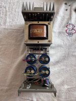
TAKE 2 - Use AC flyback to make a treater - SUCCESS
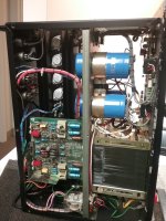
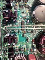
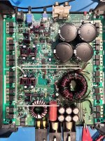
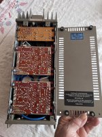
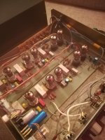
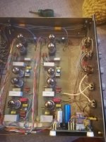
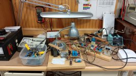
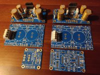
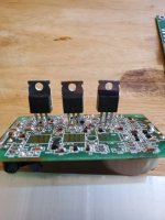
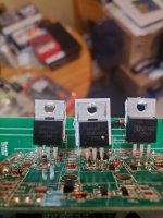
Build a driver for AC flyback and use a 300mm long 19mm Dia (3/4in) copper pipe as an electrode.
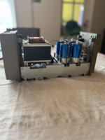
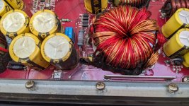
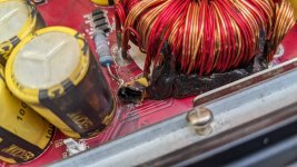
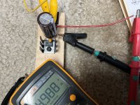
This is a small treater that does 100W at approximately 30kHz and the photos of the unit in action are below.

To my surprise, this treatment's effectiveness exceeded my expectation by a country mile - and I am serious.
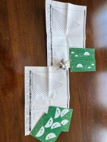
I treated an A4 sheet of acetate (from my local craft store) and the difference between the treated and non-treated areas is amazing - refer to the images below.
I used plain filtered water to check and compare the wettability.

CONCLUSION - I will treat all membranes prior to coating for sure. - thanks for the advice SY 👍 !!!


The treated section has a uniform film of water over the whole area.
Corona_1.jpg


Corona_2.jpg


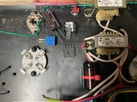
The treater in action (feediing diriver with 20V dc & 5 amps)
Corona_3.jpg

Failed transistors on Mythos ST?

Hi!
I'm not sure if this is the best forum since my question might straddle a few subforums. If there is a better place for it please let me know.

I got a Definitive Technology Mythos ST that has blown transistors in its built-in subwoofer amp. I'm trying to find out if it would make sense to replace the transistors or just replace the whole transistor board. From what I've been able to gather, it's most likely a (version of) DS-300 module but he transistors have the markings removed. Even though it looks just like the board in Mythos STS I don't know if they're identical. The transistors in the STS still have their markings. I'm including pictures of both for reference.

Does anyone know if the transistors in the ST are the same as in any other DS-300 board and if it would make sense to replace them? Or if I should just swap the whole board and is it available anywhere? Did anyone make a repair like that?

FYI: I moved the transistor board from the good ST to the malfunctioning one and it worked. So it seems that the problem is with the transistor board.

Attachments

  • DS-300 Def Tech ST.jpg
    DS-300 Def Tech ST.jpg
    78.6 KB · Views: 530
  • DS-300 Def Tech STS.jpg
    DS-300 Def Tech STS.jpg
    84.3 KB · Views: 576

Finished KT120 Mono Set

I finally got around to building a matching "color" pre-amp for my KT120 mono blocks and am loving the sound from them! Gut punching bass and overall detailed yet powerful sound. I ended up with an idle bias @ 90ma at ~500V across the tube using early production KT120 tubes. These early tubes will bias at 115ma without distress (new production won't!) but I don't need the extra few W the hotter bias provides and they still have that rich "KT120 sound" at 90ma. At 80ma and lower, they definitely lose that unique sound these tubes give. Shout out to Thermionic Labs for the output transformers I used for this build!

For anyone duplicating this set, on the preamp setup: I found adjusting the output volume control to half, and then adjusting the input gain pots to the upper end of your normal listening level seemed to work really well, obviously you can adjust the balance between the input and output gain to your taste.

www.skunkiedesigns.com

amps.jpg

Class D audio amplifier design HELP PLS

Hi guys I am attempting to simulate (MultiSim) and build a class d amplifier with the following specs:
AT LEAST 5W RMS output
single power supply
connected to 8 ohm speaker.

I have seen a few circuits online surrounding the IR2110 gate driver: Login to view embedded media I would like to implement this circuit, however I'm having doubts because I'm struggling to simulate it.

I have provided what graphs I can, if anyone could shed any light as to what the hell I'm doing wrong please fire away.

Login to view embedded media

Electro Voice EVX-180 for subs, EVM-15L for mid bass? Mostly classical voice, piano, strings

What would the experienced audiophiles think about this setup for non-modern music (if one disregards Stockhausen, Reich et al.)?
I just got hold of two 283 litre 4-port , single EVX-180 boxes at a great price. I have two EVM-15L which I initially wanted to port into lower frequencies but don't need to now.
I have a setup with an LPG 10" with a 12" drone, LPG 50mm dome midrange and 25mm LPG dome tweeter.
I feed these with an ancient Bedini 100W+100W class A for the subwoofers, an Aronov LS-960 for the mid, and a low cost Chinese tube amp for the highs. I'm using a Rane active crossover.
That's background.
Question: Would using the EVM-15L give me a more satisfying experience for the mids? Given that I'm mostly listening to voice, strings and piano?
I'm also picking up a pair of Audax HM170Z18 today.
I also have two EV DH-3 horn mid-high.
Some additional background: I have two Karlson 15 with University tri-axial and JBL fullrange, and two Karlson 12 with University 312 diffaxials.
These don't do it for me anymore, though.
Which of these would you put together? This is likely my last build.


Legendary true surround-sound (and stereo) tapes from 1970, downloads available for the first time

Mahler-3rd-Horenstein-Cover 400ph copy.jpg

Classical recording engineer Jerry Bruck (who later emerged as a Mahler scholar to be contended with) set up a separate parallel "experimental" signal chain at the London Symphony Orchestra's legendary 1970 Mahler Third Symphony recording sessions for the UK record label Unicorn, which were conducted by Jascha Horenstein. Jerry was developing his "Tetrahedral Ambiosonic" 4.0-channel surround system.

Jerry's tapes languished in storage, with only one movement ever edited, and that one for private demo purposes only. However, many Mahlerites were aware of Jerry's experimental recordings, which indeed were mentioned in the pro-audio magazines of the time.

Starting in 2020, High Definition Tape Transfers transferred Jerry's tapes to 192/24 digital. And then began the massive task of duplicating all the edits that Unicorn's engineers had done to their own master tapes.

The results are spectacular (although I have only heard the stereo channels), and even better, HDTT (High Definition Tape Transfers) is giving away a nearly five-minute 24/96 free download of the opening of the first movement, which is scored for eight French horns and percussion, except this recording used nine French horns.

Obviously, there's a lot to unpack here, which is why my Tracking Angle article/review runs past 4,000 words. [That's a hyperlink.]

If you like it, please leave a comment there.

Note, to access the download giveaway, you have to click on the link to HDTT's website, and then scroll down to the bottom of that page.

amb,

john
  • Like
Reactions: head_unit

Rail voltages after rectifier

Hi, Hope some of you can help me with this.

I have a Marantz PM6010 KI Same PCB as the PM66 PM68 etc. I think.
There were some cracked traces around the rectifier. I've repaired the traces.

When I turn it on it can take a while for the protection relay to switch on, some times it does not, sometimes it's with in 20s. Maybe another trace/joint that I missed.
The main filter caps (C801 and C802) have a bit of a bulge in the top, so I will replace these.

I'm seeing 24-0-24 AC (ideal 28.7VAC) on the secondary before the rectifier and +36.5VDC -48VDC after the rectifier and on the power amp rails (should be +/-38.4VDC). This section is unregulated. I took these measurements with no load on the amp but, it still behaves the same with the speakers connected. When the relay clicks in the readings are the same.

Is this to be expected from these amps, is there a common fault that cusses this or is it what I suspect and caused by the a (probably) damaged rectifier and dead capacitors.

With the power delivery line losses and so forth I'm not surprised by the 24-0-24 and therefore the +36.5VDC. It's the -48VDC that is confusing me.

PSU and power amp right channel attached.

Thanks

Tom

Attachments

  • Screenshot 2024-02-21 215803.png
    Screenshot 2024-02-21 215803.png
    89.4 KB · Views: 128

Building Box for a Markaudio 7.2HD, could use some advice on an irregular shaped box

I'm designing a custom desk for myself and want to integrate the speaker design into the desk. I'm coming at the box design backwards. I have the shape in mind already and am hoping that it sounds decent.

The speakers I'm going with from solid reviews I've seen and the aesthetics are Markaudio Pluvia 7.2 HD. Based on the current dimensions of my design I'm at about 10L of space. I haven't cut anything yet so I can still make changes. One option would be to have the speaker box keep the same width and length (5"x4") but continue straight down for another foot or so and cut through this area.

This is the back of the desk and that shelf was just going to be used for wire management. The box will be fully enclosed just left the covers off so you can see the design.

Is the shape of this chamber going to cause any issues with sound? I was going to go with 1/2" plywood for this part.

Desk - Speaker Box.png


Desk.png

12VDC heater module for 300b DHT

Clearing out some files, I had shared this on SkunkieDesigns’ forum for 300b amp builders there and thought it might help someone here.

I had seen photos @stephe had of wiring these components, and I wanted something a little more compact so I played around with the components a bit until I had them arrayed as in these photos.

I spaced the mounting holes 50mm apart for closest workable distance between components.

White block is heat sink ceramic for better/more thermal conduction into an alloy heat sink..Drilled holes in scrap wood as a template and used Kynar shielded wire for output to filaments. Maybe not necessary, but I had it around and it can't hurt.


First, flip rectifier over to line up ++ and -- with Voltage Regulator, bend leads outward to align, put on some heat shrink for insulation, solder. Bend center AC leads UP and away from center. You can solder these easily once the units are mounted inside. leads are all about 3-5mm off the plane of the steel plate I used for the amp. top, no shorts/insulation required but it's good practice I think to put heat-shrink insulation on where I can "just in case."


Now attach tantalum 10uF cap. 22uF and output leads. Large filter cap leads are bent and cut about 5mm wider than the "rails"; insert one side under one rail and twist to get other side under previously soldered Ground - you might need to use a pair of needle-nosed pliers taking care to get capacitors/components in order: Rectifier out-6800uF Electrolytic cap-10uF Tant. Cap.- VR- 22uF Tant Cap - output. The 10uF cap in one pic close to the insulation was moved forward a bit for the 6800 uF cap. They work great.

1708871463320.jpeg

Attachments

  • IMG_2927.jpeg
    IMG_2927.jpeg
    641 KB · Views: 58
  • IMG_2930.jpeg
    IMG_2930.jpeg
    641.4 KB · Views: 56

MOSFET J-351 v J-352

I have an Amp which I am trying to re[air, I need to change the MOSFET, the P-type had 2 x J-351.

These are hard to come by unlike the J-352. Would it be possible to use the J-352 in place of the J-351, I have been led to believe that the only difference being that the J-352 is up to 200V drain source compared to the 180v max.

https://www.web-bcs.com/transistor/tmfet/j0/J351.php

https://www.web-bcs.com/transistor/tmfet/j0/J352.php

Is this safe, recommended?

Thanks in advance.

For Sale Sony VFET 2SJ18

sold out!

IMG-20240104-WA0000~2.jpg

A pair of these can be used to build this papa's project:
https://www.diyaudio.com/community/threads/diy-sony-vfets-os2-official-thread.384256/

The OS kit for the project above using this Vfet is still available here
Only 2 kits left as of the time of this post edited, so grab it fast!

Asking for $85/pair (shipping & PP fees included)

Please note: I only tested them as suggested in Sony Service Bulletin no.62 and they all passed this test.

Thanks for looking
  • Like
Reactions: prakit

Repairing German vintage speakers?

Hello everybody,

I postet to early so I edit:

I bought a set of two Canton GLE 70 speakers (1978-1981) at a local thrift store. The guy there promised me that I can return them and get my money back and told me I should test them if I want them. So i took them with me.

This ist the speaker: https://www.hifi-wiki.de/index.php/Canton_GLE_70
I paid 30 for the set.


One speaker sounds very good the other has problems. I think that the midrange driver is gone but I'm not completly sure, could also be the tweeter.

The Speaker has a tweeter fuse built in on the backside. I switched the fuses of both speakers and after this both speakers sounded awful. When I switched them back the left one sounded good again.

I'm an absolute noob but I like the brand and model and thought guys that can build speakers could probably help me.

Thanks in advance!
  • Like
Reactions: Freedom666

Design of passive preamp. Transparency of attenuators.

Hi and thanks for your help. I have built a bottlehead kit to learn to solder and am going over circuits trying to teach myself. I thought a good first project would be a switch or passive preamp, which I need in any case. I nave a DAC that sounds good being fed directly into the power amp (It has a digital volume control). I also have a phono setup that is fed into a phono pre, but needs volume control or potentially a buffer before going to the power amp. The whole system is balanced. I am thinking of building a switch with stepped attenuator on one of the paths. Is there a good choice for switches designed to be wired as balanced switches, and should I use a pot, transformers or a stepped attenuator? Also if I go ahead and put attenuation on both circuit paths, just for versatility later, will one of these methods be more transparent when the attenuator is set to full volume? Thanks a lot for your help. I wonder if there is a plan, kit, or something like that.
  • Like
Reactions: SimpleJim

Acoustat Stator Wire Repair: Hints and Lessons Learned

Preface
* This report follows on from "Acoustat Magne-Kinetic Interface MK-121-2 - A Successful Restoration" recently posted to the diyAudio site: https://www.diyaudio.com/community/...ace-mk-121-2-a-successful-restoration.404764/

History
* These Acoustat Model 2 Slimline Series electrostatic loudspeakers, serial numbers 104333 and 104336 I purchased new in 1980 from Straight Gain Electronics, Toronto ON.
Acoustat_Model-2_Setup_3.jpg

Figure 1. Acoustat Model 2 home setup - photo taken October 2023 after restoration.

  • I was extremely pleased with the sound quality of these electrostatic loudspeakers throughout 20 years of worldwide assignments in Canada, Japan, UAE and UK, beautiful sound no matter where they were setup. Sadly, I had to put all my audio equipment into storage in 2001 due to shortage of living space.
  • Early 2022 brought my Acoustat Model 2s out of storage and powered them up for the first time in 20 years, and although the speakers were still working and usable, they needed considerable work.
  • My goal was to fully restore these speakers to their original (or better) condition, while keeping their external appearance original.
  • Having no experience in repairing an electrostatic speaker, I proceeded cautiously with this repair of the stator wires.

Initial Symptoms
a) When powered up, annoying hum noise coming from both interfaces.
b) "Snare drum" sound whenever speakers are moved.
c) When powered up, persistent clicking noises from the speaker front faces.
  • Issue a) has been addressed in the report, "Acoustat Magne-Kinetic Interface MK-121-2 - A Successful Restoration".
  • Issues b) and c) are addressed in this report (a future posting "Acoustat Diaphragm Heat Shrinking: Hints and Lessons Leaned" is under preparation).

Observations before Repair
* Lowering the grille cloths to expose the panels revealed several problems with the stator wires (Fig 2.), including multiple broken glue joints, wires bent out of shape/overlapping, wires pressed against the diaphragm etc.

Acoustat_104333_Left_Rear_Panel_Base.jpg

Figure 2. Example back side of one panel showing broken glue joints, stator wires bent, stator wires pressed against the diaphragm.

  • To assess the scope of repair work, this series of Acoustat model 2 is configured with two, 3-wire panels per speaker, for a total 8 panel sides needing inspection and repair (2 sides per panel x 2 panels per speaker x 2 speakers). While one of the panel sides had only a few broken joints, all the other panel sides suffered from several hundred broken joints.
  • While this presents a daunting task, the good news is the repair procedure is not complicated nor is any special equipment required, but it does require perseverance as it is a tedious and time-consuming job.

Materials and Tools
Stator_Wires_Repair_Tools.jpg

Figure 3. Example of commercial and hand-made tools, adhesive for plastics.

Table-1_Tools_Materials.png

Table 1. Description of repair tools and materials.

  • From a visual inspection of the stator wires its not always apparent where the problem joints are, using a small Q-Tip to gently press on the stator wires proved effective in identifying weak or broken joints.
  • For adhesive, I used several tubes of Cemedine "Super X Gold", due to its suitability for a wide-range of plastics, high-strength, high-temperature rating (a consideration for diaphragm heat-shrinking), and quick drying to a semi-hard, semi-translucent finish. Although not tried, other adhesive brands can also work well. https://www.cemedine.co.jp/global/en/technology/elastic/superx/index.html
  • To prevent adhesive from contaminating the diaphragm, I used the blunt end of a wooden toothpick to carefully apply a small dab of adhesive only to the stator wire and panel cell of each broken joint.

Repair Workflow
Acoustat_Stator_Wire_Repair_Flowchart.jpg

Figure 4. Example of stator wire repair workflow.

Acoustat_104333_Left_Rear_Panel_Base_paper_clips_1.jpg

Figure 5. Beginning of repairs to the back side of panel shown in Figure 2, with Left and Right hooked paper clips in place.

Acoustat_104333_Left_Rear_Panel_Base_paper_clips_9.jpg

Figure 6. Continuation of repairs shown in Figure 5 with more Left and Right hooked paper clips in place.

* As described in the flowchart (Fig. 4) and shown in Figs. 5 and 6, the repair steps may need to be repeated several times until all joints have been repaired. Patience is needed, this process can take several months as seen in Fig. 7. From my experience, I could spend only a few hours each day on these repairs before a hand cramp or fatigue set in. There's no need to rush it, take the time to do the repairs carefully.

Acoustat_104333_Left_Front_Panel_paper_clips_after_3-months.jpg

Figure 7. Example of front side of panel repair, progress after 3-months - not finished yet! (Picture rotated +90 degrees to fit).

  • In my case I spent about 5-months on this extensive repair, the panels cleaning process consisted of daily vacuuming, once a week blowing with soft compressed filtered air, and before applying any adhesive carefully cleaning the exposed stator wires and cells with isopropyl alcohol.
  • To explain the flowchart step "Test Integrity of Joints (play loud music, tap sides of wood frames)". Although this repair process can be tedious, there's no rush to complete it. Whenever the adhesive has cured and all paper clips have been removed, the speakers can be powered up and you can enjoy listening to music. When I played loud music, I believe this put stress on the stator wires causing other weak joints to fail - I believe this is a good thing because it accelerates the inspection and repair process, better to identify and repair weak joints sooner rather than later.
  • A useful remedy described by Mr. AAM on the diyAudio site to dislodge trapped foreign particles advises simultaneously slapping both sides of the wood frames (with power off!) with the palms of your hands, and indeed this does work. However, it also exposed more weak joints causing them to fail, but again I believe this is a good thing - the earlier you can identify weaknesses and fix them the better.

What did this Repair Accomplish?
  • After performing repairs almost daily for 5 months, did I have something to show for this effort? Yes!
  • Happy to report all repaired joints remain intact, none have failed. The thorough cleaning process followed by applying a strong adhesive were likely contributing factors.
  • As mentioned in Initial Symptoms, "Snare drum sound whenever speakers are moved." Pleased to report this is fully fixed, eradicated. This makes sense, with the stator wires now restored to their proper positions they can no longer rub against the diaphragm.
  • Also mentioned in Initial Symptoms, "When powered up, persistent clicking noises from the speaker front faces." Although huge progress was made with all panels, one panel in speaker 104333 continues to make random clicking noises (the other 3 panels are silent). One theory about what could be happening, when stator wire joints break, the repair requires thorough vacuuming and cleaning, such that when the cleaned parts are glued back together there is no more ionization path. I don't know, but possibly the ionization path then moves to a different area, resulting in a new clicking noise until the joints in that area can likewise be cleaned and repaired – an iterative process.

Final Notes
  • In summary, pleased to report both speaker's condition is vastly improved now, although for the one panel in speaker 104333 I'm not sure there's much more I can do for it and may be looking for a panel replacement. With that said, I haven't noticed any effect on audio sound quality, both speakers play music beautifully, together with the restored MK-121-2 interfaces the sound quality is outstanding.
  • It's understandable that over the years glue joints can deteriorate and break resulting in the stator wires becoming loose, but unsure what caused some of the stator wires to be bent out of shape to the point that they could not be fully straightened. As I have owned these speakers since new and always looked after them its puzzling.
  • While I believe I successfully repaired all visibly broken stator wire joints, there could be other joints that might potentially fail in future. For this reason, in the next few months I'll plan to pull down the grille cloths again and make another inspection and perform repairs if needed. This could be a heads-up for other owners of older Acoustat models, if the stator wires have not been recently inspected its worth checking.

Appendix
Referencing the setup displayed in Figure 1 "Acoustat Model 2 home setup", to share restoration projects of other vintage/classic audio equipment.
  • Like
Reactions: Big Be and dequad

Dented dust cap repair tip

I once had my dust caps on a pair of (paper cone) speakers punched in, by a toddler, obviously. At the time I was dating a massage therapist and she had left some of her equipment at my place: a pneumatic "cupping" tool. I was able to select the perfectly matched size cup and suck the dent out. It worked! Some crease marks remained but looked a lot better than before.

https://www.amazon.com/Premium-Quality-Cupping-19-CUPPING/dp/B003KJC2F4

Hope this tip is useful!
Steve

Question about split power supply

I just bought a mono subwoofer amp from Aiyima with the power supply built onto the board. It has a 24vdc output for a fan and also a 15 0 15v supply for a preamp. I haven't found a low pass filter preamp that takes a 15 0 15 supply but I do already have a single supply preamp that accepts 12v-30v DC or 9v-20v AC. It has only 2 wires for power hookup the + and -. Can I use the +15v and the 0v from the 15v+/- supply on the amps PCB and not connect anything to the -15v? I have searched but finding info on split rail systems is hard specially about only using half of it.

The best way to reduce overlap

I've been tweaking my 3-way crossovers. I reduced the midrange's amplitude by adding a series resistor before the midrange's filter, or at the input side. It resulted in attenuating the midrange level by about 2 dB.

After listening test, I thought there was dominance from the woofer. Therefore, I realized it was required to reduce woofer's operation. As far as I can think, I have two means.

A) Lowering the woofer's cut-off frequency.
I.e., from 300 Hz to 280, 260, 240 Hz, etc., until find the sweet spot, and keep the Q, or product of L and C, as original.

B) Lowering the woofer's knee or Q.
I.e., alter the ratio of L and C to vary Q, but retain the 300 Hz cut-off frequency in its place.

Which one do you prefer?

Attachments

  • comparison.png
    comparison.png
    24.5 KB · Views: 69

WTB K & K Balanced Shunt Switched Attenuator

A bit of a long shot but does anyone have K&K Balanced Shunt Switched Attenuator surplus to requirements, or the K&K kit documentation/schematic that I could utilise to build my own.

I would prefer to have purchased from K&K direct but it seems Kevin has retired and is no longer operating sales on his site. I have messaged his contact mail address from previous purchases but have not had a response.

http://www.kandkaudio.com/line-stage/

Does anyone know what happened to Isoda Electric?

Hello, around 2016 I received some samples and custom build cables from Isoda Electric in Japan to be used for resale and for our speaker prototype.
After awhile i lost contact with Mr. Yukido Isoda..........I have tried to look him up but he seems vanished. Do anyone know what happened, is the company gone? sold? taken over by the family and ended up with same destiny like Graaf (Italian OTL tube amp manufacturer)
Curious coz I like to buy a batch of cables.
Best
Mike

Behringer 1C vs DIY Dayton Audio PS95 vs DIY Dayton Audio RS100

Hi all, after many years of just being a passive reader I'm thinking again of some modest DIY adventure 😀

I'm putting together a minimal 5.1 or 7.1 system for piano practicing and occasional music listening.
I have a piano software that allows me to place up to 5 virtual microphones in a virtual room, so I can produce an immersive output with it.

I have two main requirements:
  • I can't afford to have speakers that rattle or vibrate at specific frequencies. I noticed that some cheap speakers don't do that with normal music listening, but when playing solo piano, they do. That would make me go crazy.
  • The speakers will be placed fairly close around me (1-1.5 meters maximum). We're not talking about filling an entire living room with sound.
I'm a bit on a budget so I've narrowed down the choice down to these three options:
  1. Behringer 1C
    • PROS: simplest option (no DIY required), two-way with woofer/tweeter, decent power handling (25 watts RMS), can be bought second-hand for a lower price
    • CONS: no frequency response measurements online, specified frequency range is super suspicious (60 Hz to 23 kHz -20 dB 🤣), it's unknown if they may rattle or not
    • PRICE: around 50€/speaker new, around 30€/speaker second hand
  2. Dayton Audio PS95-8
    • PROS: fairly cheap, fairly linear response up to 20k, requires a sealed box of only 1.15lt / 0.04ft³
    • CONS: lower power handling (10 watts RMS)
    • PRICE: around 25€/speaker new
  3. Dayton Audio RS100-8
    • PROS: higher power handling (30 watts RMS), requires a sealed box of only 1.41lt / 0.05ft³, seemingly highest quality
    • CONS: a bit on the expensive side, less linear in the high frequencies than PS95
    • PRICE: around 46€/speaker new
For Dayton Audio loudspeakers, I would build sealed MDF boxes with spring terminals and internal stuffing. The upper price estimate is around 10€/box.
I can also do some corrective active EQ by software with biquad filters. Same applies to the crossover with the subwoofer.

If you have also other suggestions other then the three above, I will welcome them.

I'm looking forward to your feedback!
Thanks in advance 🙂
  • Like
Reactions: xXBrunoXx
Projects by fanatics, for fanatics
Get answers and advice for everyone wanting to learn the art of audio.
Join the Community
507,650
Members
7,882,733
Messages

Filter

Forum Statistics

Threads
405,964
Messages
7,882,733
Members
507,650
Latest member
Sanjiev