For Sale Marantz CD 50 player, no-oversampling and tube output

Hi,

I am selling one upraded Marantz CD 50 player.
Is in very good condition and the changes have been made are:
- changed few capacitors from power supply;
- the standard op-amps output stage replaced with tube output stage;
- put in no-oversampling mode;
- changed the decoupling capacitors of the TDA1541 DAC.

The price is 350 euro (shipping included). I can ship only in EU countries.

Please send DM for more details.


  • Like
Reactions: passive420

Tentlabs CD player repair

I am a friend of the son of Eric Thomas, who used to own and run Beauhorn. Eric recently passed away and left a number of interesting and unusual pieces of hifi equipement to his family. This included a Tentlabs CD player, which is unfortunately only working on one channel.

Does anyone know anyone in the UK (preferably south east) or possibly Europe that would be able to look at this with a view to fixing it?

Thanks for your help.

Help me with this DSP thing MV silicon BP1048B2 2.1

On the effects is only "2" and "4" the 4 is for the subwoofer, and 2 is for stereo i think(2 and 4 from the total of the 4 outputs of the chip in theory)
I need separate efects for each channels! Not only the "2 " output, otherwise is useless, what to do? 🙁

Attachments

  • MVIMG_20250127_145920.jpg
    MVIMG_20250127_145920.jpg
    172.7 KB · Views: 225
  • MVIMG_20250127_145910.jpg
    MVIMG_20250127_145910.jpg
    337.1 KB · Views: 178

Bluetooth frankenspeaker with old full range chassis

Hi!

I found two old speakers with fullrange chassis. My idea is to build a bluetooth-corner-frankenspeaker out of them. While I don't think they would be exactly HiFi, I thought the typically warm sound with good point-sourcey understandabillity can be achieved. Subjectively they have a certain quality to them and go quite loud, as proven by feedback. Ooops!

PXL_20250406_120453548.jpg
1743943012050.png


I meassured them in their old enclosures and they seem to have some problems:
There is a huge phaseshift when the small cone starts to load at 1kHz, unpleasant harshness caused by the bump around 2,4kHz (?) and uneven hights, which could be caused by my quick meassurement setup.

1743944592177.png


Good part: despite the issue around 1kHz, phase response is really nice and it seems to me like they only need an EQ around 2,4Hz (-6dB/Q=1 maybe) to get that pleasant warm sound for a kitchen radio.

Next up would be finally soldering my measuring cable for T/S params, designing a BR enclosure out of scrap parts and buying a china bluetooth-dsp-amp board.

One question: is the phaseshift immanent to that kind of speakers?

All the Best! robo-klaus

ICEpower 1000a

Good afternoon all from a rainy England (summer "eye roll" )

I have 2x icepower 1000a boards with the same issue.
The board powers up ok, however produces no audio. It does not trigger standby or trigger the protection shut down. It just sits there with the peotection circuit happy as Larry just producing no sound.

Is there a common issue on these boards that would produce the same symptoms? As I have 2x boards with the exact same issue.

Unfortunately I do not have an oscilloscope, I am very DIY. I do however have a multimeter and good basic knowledge of circuitry.

Attachments

  • 20250423_133540.jpg
    20250423_133540.jpg
    363.1 KB · Views: 38
  • 20250423_133550.jpg
    20250423_133550.jpg
    466 KB · Views: 36

Finally, an affordable CD Transport: the Shigaclone story

While the transport I'm presenting in this thread is not really a clone, it all started with me picking inside Shigaraki and posting some pics on audiostereo.pl forum.

As those guys are quite resourceful, they quickly found that the same mechanism and similar chips are used in JVC RC-EZ31 boombox and the rest is history.

Now, after all those months, I'm quite puzzled why nobody so far came up with similar application? After all, Gainclone and Phonoclone gained so much popularity that easily surpasses the originals.

It all started when last September somebody asked me to build a PS for Shigaraki transport. I did that and had a chance to play with the transport in my own system. And while I was extensively using CEC TL0, ML31.5 and ML37 at that time, I was quite impressed by Shigaraki. In some ways it offered performance virtues none of my other transports could dream of, specifically the freshness and vitality of the sound, with very well defined PRAT (BTW, the PS based on 70VA Hammond transformer was in no way inferior to original Dumpty).

I was almost ready to buy a used Shigaraki or Flatfish when the alternative option emerged on Polish Forum. And although I was quite involved during all those months in development process, the discovery of the transport source and some fine points of modifications should be credited to other forum members there.

Now, after 6 months, my transport is almost completed and it took the spot of CEC TL0, becoming my main digital reference (I still keep TL0, both Levinsons and loaned Flatfish for comparisons).

The whole story can be read here: http://www.audiostereo.pl/forum_wpisy.html?temat=36475&p=1#k

.
An externally hosted image should be here but it was not working when we last tested it.


While I was quite hesitant to post this info here, I think that discovery is too good to be kept secret, with time I will provide more details.
I used Shigaclone reference in the thread topic, but after some time will ask moderators to remove it.

Attachments

  • cdp.jpg
    cdp.jpg
    87.8 KB · Views: 38,510

TCP/IP to AES3 Converter (STM32 + DIT4192)

Hello everyone,

I'm working on a device that converts audio data received over TCP/IP to AES3 format.
For this, I plan to use the DIT4192 chip together with an STM32F407/417 microcontroller.

The device is intended to support:
  1. Sample rates up to 192 kHz
  2. Up to 24-bit resolution
  3. No audio proccessing is needed
I would really appreciate any help or suggestions, especially with the following:
  1. What do you think about the choice of DIT4192 + STM32 for this task?
  2. Are there any good C/C++ libraries (for Linux or bare-metal) that can handle audio decoding (MP3, WAV, etc.) and output via I2S (my guess STM HAL/LL does the work, but not sure)?
  3. Do you know of any open-source or DIY projects that are similar or could be helpful as a reference?
Thanks in advance!
  • Like
Reactions: eclipsevl

FET-hex explendit amplifier

Hello

Recently I have build VSSA amp (shaan version bit modyfied) and I am very happy with it.
I had few irfp240/9140 pairs in stock so I decided to build another version (as I am not an expert some upgrades may be needed).
Bellow schematic, board, and measurements. The measurements were done on prototyp board and all components weren't matchet (just taken stright from the box).
Bias is stable, cold amp seted to 100mA (15C) hot amp 92mA (78C), I didnt have irf540/530 so I used irf840 instead. I think that amp can use bit higher power supply than +/-35V.
Amp is playing really good.
Thanks to LazyCat and Shaan


Ps
I was thinking If it would be recommended to leave 0,1R source resistors and put 47R gate resistors instead 100R ?
My sound card is not the top notch and is creating some high order harmonics artefacts (there are present at the same place on different amplifiers measurements).

Attachments

  • DSC_0583r.jpg
    DSC_0583r.jpg
    70 KB · Views: 8,838
  • FET-hex ccs v4.pdf
    FET-hex ccs v4.pdf
    12 KB · Views: 3,259
  • FET-hex ccs v4 top.brd.pdf
    FET-hex ccs v4 top.brd.pdf
    43.7 KB · Views: 1,580
  • FET-hex v4 zelazko.pdf
    FET-hex v4 zelazko.pdf
    55.5 KB · Views: 1,784
  • fet-hex 20V.png
    fet-hex 20V.png
    69.6 KB · Views: 8,464
  • fet-hex 3khz20V.png
    fet-hex 3khz20V.png
    50.7 KB · Views: 7,936
  • fet-hex 5khz20V.png
    fet-hex 5khz20V.png
    49.6 KB · Views: 7,715
  • fet-HEX 8R plus 0.47uF square.png
    fet-HEX 8R plus 0.47uF square.png
    117.2 KB · Views: 7,640
  • fet-HEX compensation.png
    fet-HEX compensation.png
    154.7 KB · Views: 1,407
  • fet-HEX 8R plus 0.47uF.png
    fet-HEX 8R plus 0.47uF.png
    130 KB · Views: 1,320

For Sale Salas DCB1 Hypnotize with hotrodded options

I'm selling a DCB1 board with three current bias options: 1.5, 8 Ohm (Caddock MP930s) and 20 Ohm (Xicon 5W) so you can choose between > 850mA, 200mA or 90mA bias current. In my opinion the higher the bias the better the sound quality.

All parts are very good quality mostly if not all from Mouser
All fets signal and psu are original Toshiba's bought from Mouser, the signal ones are 2SK170GR fets ( > 6mA ) closely matched resulting DC offset which starts at 0mV and settles around -2mV and -3mV for each channel
Psu caps - 10.000uf Nichicon Gold Tune KG, 100uf Elna Silmic II, Wima MKP10
Signal resistors - Dale RN60C precision 0.1 % 50ppm

Soldered with Kester 44 (63/37)

135 euros included shipping worldwide. Paypal for friends

dcb1.JPG

Attachments

  • dcb1_working.JPG
    dcb1_working.JPG
    327.8 KB · Views: 184
  • dcb1_bottom.JPG
    dcb1_bottom.JPG
    285.9 KB · Views: 188
  • Like
Reactions: naca5

How to connect driver with spring loaded connectors

Hi,

I'm planning to build Troels Gravesen The loudspeaker 3, the drivers has arrived. The bass unit - 18 Sound 15W700, has spring loaded connectors with big holes.

What is the best way to connect the speaker cables, do I just strip the wire and let the spring make the connection, or shall I put banana plugs on the cables and push them through the hole? I feel like this is a stupid question but I want to make sure the cables don't come loose .

There are plastic caps on the top of the connections, similar to speaker terminals but I don't think these are to be removed, as there would be no way to differentiate between the positive and negative terminals.

Thanks for your help.

Hi from Italy!

Hi everyone! I'm Stefano from Italy.

I'm a master student in electronic engineering (relatively) close to graduation. I normally work on digital stuff (digital radios and digital design for mixed signal applications) but I have a long standing fascination towards analog design, with focus on music and audio in general.

I started out with a thrifted Sony AVR (DB840) with thrifted Revac HP 102 loudspeakers. Now I'm working on a malfunctioning Nikko NA-400 and I'm trying to build my own version of the STK465 amplifier module with modern discrete components to make it available to the community since reliable new old stock by Sanyo is dwindling and clones available on the internet come from unknown sources.

Boyuu hifi Equis A10 EL34B+6N2 SE Tube Amplifier with 5Z4P rectifier: review and mod

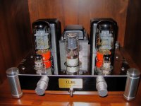
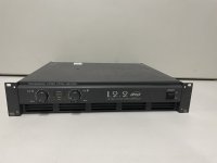
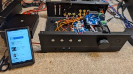
I admit I was highly reluctant to buy a Chinese product, like most of the people in my country, but at the end I did it, and have absolutely no regrets: this Chinese tube amps is probably one the biggest bargains in the audio world.

Description:
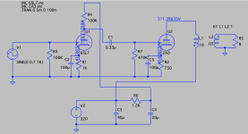
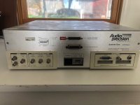
12Wx2 EL34B+6N2 SE Tube Amplifier with 5Z4P rectifier

Official Features:
- Input voltage: 220V
- Power supply: 160W
- Output power: 12W x 2 (ultra-linear connection)
- Frequency response: 20Hz - 28KHz
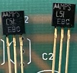
- military grade dual triode 6N2J as voltage amplifier
- Shuguang EL34B as power tube
- Shuguang 5Z4PJ as rectifier
- THD: <1% @ 1KHz
- Output impedance: 4Ohm and 8Ohm
- Input Impedance: 100KOhm (two input signals)
- Input sensitivity: 750mV
- SNR: >88dB
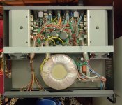
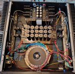
- Power transformer: 96x50mm 0.35mm z11 using imported 96mm slicone steel plates in 0.35mm thickness,Stack thickness is 50MM to ensure sufficiant power and low heating.
- Output transformer: 66x36mm 0.35mm z11 using 66mm slicone steel plates in 0.35mm thickness,Stack thickness is 36MM.
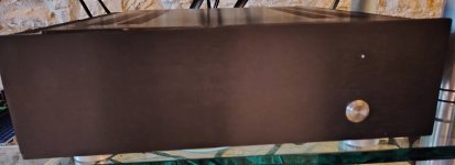
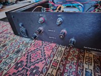
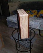
- Mirror surface stainless steel enclosure
- Diamond cutting corner feet
- Alps potentiometer
- Powder coating transformer enclosure
- Dimension: LxWxH 310×268×165mm
- Weight: 12Kg
- Price c.a. $250.00 + $110.00 shipment (purchased at 300 euro in Italy)


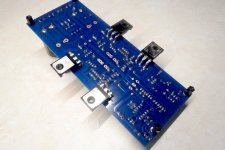
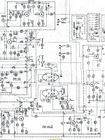
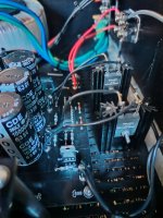
Additional circuital info:
-PRO: really amazing quality/price ratio: this amplifier has without any doubt a superb design for its price
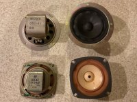
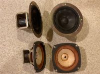
-PRO: The mids are clean and the bass/highs are all there (I'm listening with 16 ohms fullrange loudspeakers). Not too much bright (which I really like), it sounds quite veiled and rolled-off (with stock EL34) but sufficiently detailed, thus there is no way you will get ears fatigue with this tube amp
-PRO: voltage amplifier with triodes in parallel to reduce noise and increase gain
-PRO: hybrid bridge rectifier using a valve rectifier and a pair of silicon diodes. You will still get the valve sound without the harshness of the silicon diode cutoff in reverse bias.
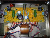
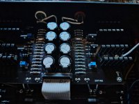
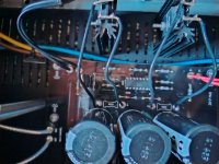
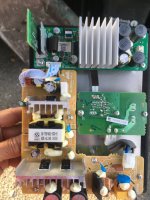
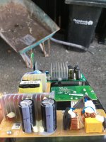
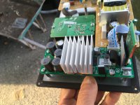
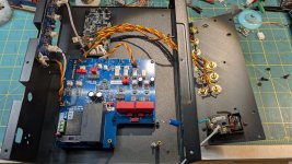
-PRO: choke is used as a power supply filter element
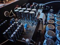
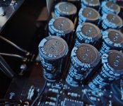
-PRO: Panasonic, Philips and Nichicon brand capacitors
-PRO: all components are well dimensioned and never run hot
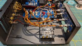
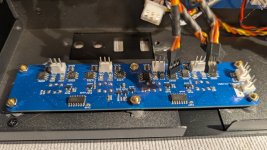
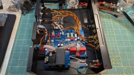
-PRO: PCB and very clean wiring
-PRO: safety: the amplifier is internally correctly grounded/earthed

-CONS: the noise floor is quite poor, but this noise is modest and does not at all interfere with the listening
-CONS: missing 16 ohm output
-CONS: missing EL34 grid stopper resistor
-CONS: the inside iron core inductor looks not to be well fixed to the chassis (only from one side), which, I think, could be a problem if you think to a very long shipping distance
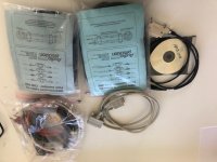
-CONS: shipping box content is minimal, that is just the amplifier without brand, marks or labels and no documentation (but this is fully justified by the price)

______________________________________________________________________________________________________________

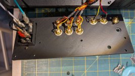
MAJOR IMPROVEMENTS OF MINE (have immediately void the warranty!):

1) Stock version: Ultra-Linear mode connection only
Modification: added front panel “bright chrome” switch to select between Triode and Ultra-Linear mode

Triode mode is more pure, with less distortion and more open sound but the UL has more power and dynamic...it is your liking. In every amp with user-switchable triode/ultralinear circuits, triode usually sounds better.

2) Stock version: EL34B power tubes
Modification: replaced with KT66 power tubes

No self-bias adjustment is required (according to Weber Bias Calculator) since KT66 has the same plate dissipation than EL34 (25W), but KT66 has higher load impedance requirement than EL34. That is also recommended if you run, like me, a 16 ohm speaker to the 8 ohm output since you are doublig the reflected impedance. Optimal burn-in times range from 100 to 300 hours. Most changes are happening in the first 150 hours. Also the 6L6GC high-power tubes have high internal impedance and work great in this amplifier on a 16 ohm load without requiring bias adjustment since exhibit similar consumptions to the EL34B (see last page measurements).

3) Stock version: two 1N4007 (in the hybrid power supply)
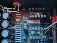
Modification: replaced with two ultra-fast SF4007 diodes, bypassed by 10nF snubbing caps

Walt Jung article gives the reasons for using fast recovery diodes and has actual measurements showing the large amount of RF hash generated by common 400x rectifiers.

4) Stock version: 220uf Panasonic Electrolytic (FC Series) cathode bypass capacitor (in the power output stage)
Modification: replaced with bipolar Sic-Safco 470+470uF back-to-back (+--+) capacitors, plus 2u2F polyester cap

Many folks have found that Bipolar Electrolytic Capacitors can make a noticeable difference when used as cathode bypass capacitors in tube amps. Read "Bipolar Electrolytic Capacitors" by Matt Seniff.

5) Stock version: unbypassed gain bias resistor (in the common-cathode triode amplifier)
Modification: added bypass cathode capacitor (bipolar Rubycon 1000+1000uF back-to-back (+--+) capacitors, plus 1uF polyester cap)

By adding bypass cathode capacitor you increase gain (recommended by KT66’s higher gain requirements) and rise mostly even harmonics. Being an even order harmonic, this is not a critical tonal issue, since even order harmonics stay musical (multiples of an octave).

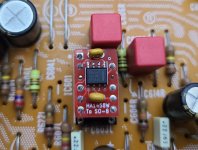
6) Stock version: 220nF/400V Philips (MKT series) coupling capacitor between stages
Modification: replaced with 220nF/500V metallized paper-in-oil K42Y-2 Soviet Military Capacitor

PIO dielectrics are appreciated for their tonal balance that is very neutral and smooth. Audiophiles, studio guys, vintage collectors can all hear the difference with their own opinions on what is best. The main thing is that I agree that the cap upgrade is a good thing.

7) Modification: added bypass film 1uF/47nF capacitors in power supply (on the back side of the PCB) in parallel to electrolytics to filter out high frequency noise.

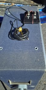
8) Stock version: three-pronged power cord with ground (earth) connected to the chassis
Modification: remove earth connection by plugging into a continental power adaptor which breaks the ground (earth)

By removing earth connection, the amplifier sounds quieter and better.

9) Stock version: no Global Negative Feedback
No Modification: give up to any Local/Global Negative Feedback

I tried from -1 to -6dB of NFB which makes a great influence in the final sound, but additional NFB made the amplifier sounding more and more as "solid-state". I preferred the stock version (no GNFB at all) since it sounds more harmonically rich which results pleasant to me.

10) Stock version: for safety reasons the common (or zero ohm) end of the OPT is grounded
Modification: floating outputs, and separated isolated L/R zero ohm returns

Amplifiers with no global feedback can leave the output transformer secondary floating, even if it is electrically unsafe. This opens the soundstage a little bit. Probably the floating outputs provides the (RF) noise-reduction benefits of balanced lines.

11) Stock version: EL34B self-biased at plate dissipation of about 15W (out of 25W max) by 500 ohm cathode resistor. That means cold/average dissipation.
Modification: KT66 self-biased at plate dissipation of nearly 19W (out of 25W max) by a reduced 410 ohm cathode resistor. That means hot dissipation.

Biasing the power tubes hot gives it a brighter and fuller sound.

12) Stock version: 5Z4 rectifier
Modification: replaced with Sovtek 5V4 rectifier (or even JJ GZ34)

The KT66s’ new adjusted bias is now drawing extra current, about 120ma, so too much close the maximum forward current of the 5Z4 (125ma max, 350V, 20V drop). The replacement with 5V4 (175ma max, 375V, 25V drop) or with GZ34 (250ma max, 450V, 17V drop) is just recommended because both tubes are low drop-out equivalents. At the end, after listening test, I even prefer 5V4 to the GZ34, probably due to the highest voltage drop and sag: the GZ34 is too close to “solid state” in the response and in some cases it yields voices quite metallic and fuzzy, for sure never as smooth and natural as delivered with the 5V4. Of course by using the 5V4 makes the KT66s running a bit less hot due to the higher drop in power voltage supply.

13) Stock version: the shared cathode resistor of the parallel 6N2 triodes is Rk= 2Kohm
Modification: triodes in the driver stage are re-biased hotter (Rk=840ohm)

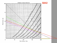
The optimal plate load for a triode is around two to three times the plate resistance (which is nearly 47Kohm for the 6N2), thus the stock anode resistor looks well-dimensioned and I didn’t modify its value (75Kohm). Remember that parallel operation needs shared plate and cathode resistors at half the single triode value.
Pay attention that 6N2J (or 6N2P, 6N2P-EV) is not full equivalent to ECC83 (or 12AX7): both have an amplification factor nearly of 100, but, a part of the filament connections, the last has higher plate resistance (62.5Kohm) and slight shifted grid-voltage vs. cathode-current curves.
Since 6N2 triodes are now bypassed by a capacitor for a higher gain, changing the cathode resistor doesn’t modify the voltage gain, but only shifts the bias point: this modifies the headroom of the driver stage and the distortion level. As the bias point is shifted, the amplifier will clip more on the top or bottom portion of the waveform.
By lowering the cathode resistor from 2K to 840ohm, not only we increase and better centre the bias current, but also we obtain a better sounding harmonic distribution, the so called waterfall of 2nd > 3rd > 4th > 5th. Cathode resistor value was in fact chosen where the measured third harmonic component was minimum and the second harmonic dominant at an output power of 1 Watt. The soundstage turned out to be more "open" and "natural" that confirms all Psychoacoustics studies which say that even harmonics give a warmer, organic, and natural sound while odd harmonics impart a more harsh and metallic sound.

14) Added a Zobel RC network between the amp and the full-range 16 ohm speaker

Any amp is inductively loaded by a speaker, so the correct form for interpreting an inductive load on a plate current/voltage curve is an ellipse which may exceed the Max dissipation curve limit. A Zobel RC Network is designed to achieve a flat impedance, safer load.
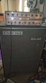
This amplifier looks to sound more comfortable driving a flat-impedance resistive-like 16 ohm load, (from its 8 ohm output taps), which results in a better 3D image and stable focus

15) Stock version: input grid stopper resistor (in series with the grids of the driver triodes) is 10Kohm
Modification: input grid stopper resistor lowered to 3.3Kohm

The stock input stopper grid resistor is 10Kohm (but the triode, originally unbypassed, had a lower voltage gain of nearly 20). After bypassing the common cathode resistor of the parallel driver triodes for a higher gain, the voltage gain reaches nearly 70, and the grid resistor needs to be reduced of about one third, from 10K to 3.3K, due to the increased input Miller capacitance.
In fact the Miller capacity (that is twice for parallel triodes) is:
Cin = Cgk + Cgp*(A+1) =~ Cgp*(A+1) =~ Cgp*21 (when unbypassed)
or
=~ Cgp*71 (if bypassed)
then, Cin_bypassed =~ 71/21 Cin_unbypassed =~ 3.3 Cin_unbypassed thus, Cin_bypassed =~ three times Cin_unbypassed
The input capacitance of the tube (Cin), in conjunction with the impedance of the grid stopper resistor (Rg), forms a simple RC lowpass filter with a -6dB/octave slope. To maintain the original low roll-off frequency, Rg resistor should be reduced to one third, since Cin has been tripled. Frequency response is now back to be ± 1dB at 16 to 20000Hz.

16) Stock version: the interstage coupling capacitor is C=220nF and the KT66/EL34 grid leak resistor is R=470Kohm. Also the 6N2 grid leak resistor is R1=470Kohm.
Modification: coupling capacitor doubled to 440nF and KT66/EL34 grid resistor halved to 220Kohm, preserving the original RC cut-off frequency. The 6N2 grid leak resistor is cut from 470Kohm to 150Kohm.

A lower value grid leak resistor will be harder to drive, but will give a more constant load at different frequencies, and hence a more extended high frequency performance. In fact, the grid to plate internal capacitance of the following stage (whose value is also multiplied by the gain of the stage, due to the Miller effect) reinjects a fraction of the output signal back to the grid. It is nothing else that a local negative feedback whose effect increases with frequency and the gain. The Miller effect can cause loss of treble if the grid resistor is too high; the lowest the grid leak resistor, the lowest the feedback, the wider the bandwith. Miller capacitance not only affects high frequency response but it adds phase intermodulation distortions as well.
By halving the size of the grid leak resistor, we double the cut-off frequency and increase it by an octave, cutting the bass response. Viceversa, by doubling the size of the interstage coupling capacitor we halve the cut-off frequency and reduce it by an octave, allowing more bass response. By choosing a lower value of the grid leak resistors, we also lower the gain a tad, but not significantly. If we make both the modifications, the two effects will compensate each other, maintaining the original RC time constant, thus the original the cut-off frequency.
It is important that we should always aim for a corner frequency of one tenth of 20Hz (2 Hz) to avoid any phase shift in the lowest bass region.
We can easily double the existing capacitance by putting another identical capacitor in parallel. Putting two identical caps in parallel is a good thing and brings small advantages because we halve the intrinsic resistance and the cap's inductance.
Many folks have done intensive testing of input capacitors: parallel film capacitors sound better to their ears as they were found to sound "faster" than a single capacitor of the same value, but we are straying into highly subjective territory here.
Moreover, we could test to put a "PIO" together in parallel with a film and foil capacitor of the same value to create a tone circuit, because a pure PIO capacitor has been found to sound smooth but rolled off in the highs.
The output impedence for two 6N2 parallelled triodes (output taken from the plates, bypassed cathodes) is about:
Rs= Ra/2||Rp/2 = 47K/2||150K/2 = 23.5K||75K = 17.9Kohm
The impedance of the following stage (KT66/EL34) is just the grid resistor reduced to R= 470K/2~ 220Kohm.
The coupling interstage capacitor has been increased to C=0.22x2= 0.44uF
The new cut-off frequency at -3dB of the low end of the band will result equal to 1/[2*pi*(Rs+R)*C]= 1.5Hz, that is a desired pole frequency less than one tenth of 20Hz.
To change the grid leak resistors brings major tonal improvement to the tube amplifier, creating a soundstage with focus and realism.

17) Stock version: single value of cathode bias resistor on power tubes
Modification: added a front panel “bright chrome” switch to select among three different BIAS options: HOT, AVERAGE and COLD

This three-positions switch allows you to select among different cathode resistors (connected in parallel) that determine three different BIAS currents and consequently let run the power tubes slight colder or slight hotter than the average.
In Single Ended amplifiers (which always run in Class A, ergo do not suffer from crossover distortion) decreasing or increasing the bias current brings little tonal improvement due to the asymmetrical clipping and waveform compression which increases the content of the second harmonic distortion and enhances its ratio compared to the third and odd harmonics.
Bias adjustment is highly recommended after having swapped different tubes or after having switched between Triode and UL mode: you can observe in the attached table that various tubes (EL34/6L6GC/KT66) show slight different measured voltages and consumptions, thus exhibit distinctive tonal behaviours.
Hot bias shortens tube life and usually sounds more dynamic and fuller, but potentially harsher. On the other side, cold bias, for which tubes will last longer, in certain circumstances produces more natural tones, even if sometimes the sound results thin and lifeless.

_________________________________________________________________________________________________________________

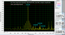
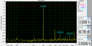
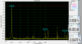
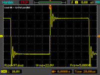
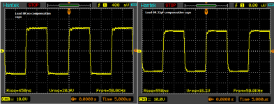
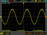
Attached curves of the A10 amplifier after all my modifications, both simulated via LTSpice and measured on a PC-soundcard.

I measured a maximum power of 3.5 Watt on 15 ohms (10% THD) in Triode mode and 6 Watt in the Ultralinear operation, both channels working.

I would not comment the curves since I think almost everything is self-explanatory: I just ask you to bear in mind the mismatched impedance between the amp and speakers (I’m running a 16 ohm cab through the 8 ohm amp tap) and that now there is neither global nor local negative feedback in the triode mode, and just a negative feedback applied to the screen grid in the ultralinear operation.

I can't disguise the fact that the ZERO LOCAL/GLOBAL FEEDBACK TRIODE CONFIGURATION satisfies me completely regardless of the higher distortion and lower power output.


ANY COMMENTS ARE WELCOME!


:c_flag: :c_flag: My Homemade Tube Amplifier website: The Sound Grail, design, schematic, simulation and measurements http://tubeamplifiers.wixsite.com/thesoundgrail :c_flag: :c_flag:

Attachments

  • A10_KT66.jpg
    A10_KT66.jpg
    166 KB · Views: 6,394
  • A10_mod.jpg
    A10_mod.jpg
    235.3 KB · Views: 6,314
  • Like
Reactions: Pashka

Linkwitz transform on a tweeter?

I have a DIY build that is effectively a Cura CA10 - the cabinets were remaindered when the company went out of business, and it seems they had PL18s and Seas H519 25TFFC tweeters. I managed to get new old stock of both, and I have them set up active with minidsp crossovers. I never found a crossover schematic for them. They've been 'on the bench' for a while but are now back in-system.

I've had a fairly simplistic crossover running on them with a very steep filter at 2.5k but I'm wondering if I could do better.

The tweeter nominally resonates at 1200, has stored energy between 1200 and about twice that, and it rolls off second order with -3db at about 1800 and flat at about 3500, it looks like Q is about 0.5.

I'm wondering if I could:
  • use an LT to flatten the tweeter's response and push the natural rolloff down so its flat above about 1000
  • then add a 4th order (might try 2nd) LR at about 2300, maybe a bit less.

The PL18 cone geometry means that the 60degree plot diverges from about 1800 and the 30degree plot from about 2500, so I would like to keep the crossover as low as I can given the tweeter's limitations.

Does that sound sensible? I don't think the woofer is up to higher than 2.5k without directivity issues

The 'ears' on the tweeter are next to each other and the cabinet is cut for that rather than the more spaced out terminals on newer tweeters, otherwise I'd probably replace with an SBAcoustics or similar. I may yet take a saw to the cabinet, but I thought I'd try first.

Not sure how I'd approach a passive crossover for these without using the tweeter's rolloff and accepting all the stored energy and raised distortion, but that's not my immediate problem.

B1-R2 PVG version with Power Supply, Volume control and Gain stage on board

I finally finished the extended B1-R2 buffer I have been working on after receiving the chassis and finding the time to do the work.
For those not familiar, the B1-R2 is the Rev 2 version of the Pass B1 single ended buffer re-designed by Papa to work with a bipolar, rather than single ended, supply.

This build is for my office that also uses an ACA-Mini with boards created so it will mount in a more standard chassis with heat sink.

I modified the B1-R2 to use the output buffer pretty much as designed by Papa (Thanks Papa! 🙏) but I also added a few other things I wanted,

This one has an adjustable LM317/337 based power supply w/RCRC front end, a volume pot and a configurable gain stage on the same board.
The AC source is a 24V AC wall transformer connected by a standard 2.1 mm barrel connector.
It is laid out so the gain stage, which uses an LM4562 op-amp, can be omitted or the gain can be easily changed. The gain resistors and the op amp are all socketed and easily changed, bypassed or omitted. Or could be soldered in if no changes are expected.

The pot is an Alps RK27 at 20k Ohms. The next build will use a slightly wider chassis that will function the same but have an additional front panel 1/8" input, an LED power indicator and use a 10k pot with a higher input Z. Using that 20k Pot with 50k input impedance was pretty silly of me. The new build will go in the main rig.

So how does it sound? I think it sounds utterly fantastic! Really open, detailed and dynamic. My office stereo has never sounded this god. It's quite a change, But of course I may have builder's bias. 🙂

I created the board in KiCad. If anyone is interested and wants the design files or Gerbers I'd be happy to share. I can also share the chassis source at AliExpress. Drop me a PM if interested.

Attached is the schematic as built. I have a new rev with tiny improvements not yet built, And it probably never will be built. I ordered the five board minimum for the first build and expect to only build one or two more.

Front.jpg
Back.jpg
TOP_Side.jpg
Top_Back.jpg

Untitled-1 copy.jpg

So
  • Like
Reactions: Ixnay and zoom777

Rare garage sale finds

I have to share this. Found these beauty’s at two different garage sales last week, got them for $10.00 per pair. The holey basket had one where the surround was separating from the cone and the other was perfect. I have only seen pictures of the black non rib cones holey baskets. The AKAI had surrounds partially separating from the cones. All have good surrounds, not stiff. I have glued the surround on them. What a great find!

Attachments

  • IMG_1100.jpeg
    IMG_1100.jpeg
    841.5 KB · Views: 144
  • IMG_1101.jpeg
    IMG_1101.jpeg
    841.3 KB · Views: 143
  • IMG_1102.jpeg
    IMG_1102.jpeg
    868.8 KB · Views: 141

For Sale Faital Pro 15PR400, BG Neo3, BG Neo8, SEAS CA15RLY, Crossover Parts

Making other projects priority, so letting these go... photos to come.

Pair of NEW IN BOX Faital Pro 15PR400 4 Ohm.
$420 + Shipping

Bohlender Graebener (BG) Neo 3.5.
New old stock $140/pair + Shipping

Three near new Bohlender Graebener (BG) Neo 8, with gaskets.
$75/each + Shipping.

Used pair, but in excellent condition, Seas CA15RLY.
$80/pair + Shipping.

I also have wired up together...
Pair of near new Jantzen Audio 0.40mH 15 AWG Litz Wire Air Core Inductor
$30/pair + shipping

Pair of near new Jantzen Audio 3.3uF 800V Z-Silver Capacitor
$45/pair + shipping

I'll cover PayPal fees.

Open to reasonable offers.

Thanks.

Why is Intel Corp dying?

I just read an article written by Intel board members. "Professor Yoffie, Mr. Hundt, Ambassador Barshefsky, and Professor Plummer all served as longtime directors of the Intel board."

I worked for Intel Corp in the late 1980s until 1997. That was when Intel Corp ruled the CPU world- Intel 286, 386, Pentium. New wafer fabs were being built in NM and AZ. Intel Corp was/is highly dependent on corporate welfare. And there was a consortium of taxpayer funded photolithography research going on. It all ended when SVG corp was sold to ASML. I always wondered how a Dutch company could buy a US funded company?

The photolithography tools were the bottleneck because the geometry of the chips were limited by the frequency of light waves. Nanotechnology. In the 1990s, the limiting factor was the placement/position of the photolithograpy tool, but magnetics were used to resolve that resolution. Talk about a gnats ***.

Today, there is talk about TSMC taking over Intel chip factories. Intel Corp might die.

1967 all germanium Farfisa BR 80, 80 w head unit fully restored now, but still yielding rather loud 120 HZ hum

A few weeks ago I found this random cabinet in a dumpster that somebody alerted me to. It was a pristine farfisa cabinet for a br-80 amp combo. A whopping 80 watts of Italian made germanium-powered instrument amplifier, with a very nice pristine JBL d130 in the cabinet along with a tell Ray oil can Echo unit. I found the actual head unit on reverb in non-functional condition. I bought it and had it mailed to me and got it functioning straight away. A few weeks later I got an actual schematic and went about shoring up any other Loose Ends. I now have the unit as restored as can possibly be, thankfully to my large collection of germanium transistors that I've accumulated over the years. But it still has a rather present 120 Hertz hum, which is entirely from the power unit, as with all of the inputs shorted or even with the input cards removed the home is still there. I realize there is a lot of possible reasons for this. For instance that this was a unit made for 110 volts now getting closer to 120, and the age of the amplifier possibly having some incongruities. I figured there has to be some way to balance the hum, as I have seen on a lot of other amplifiers. I recapped the whole thing, or at least every electrolytic that was in it. I read some post somewhere that said that the Falcon caps that were in these things were usually pretty stable. That's complete nonsense by the way! Any capacitor from 1967 that I know of is in no way stable! Certainly not in an 80 watt monster from this era. There were very few solid state professional amplifiers back then that were 80 Watts. I'm wondering if they were limited by the state of the capacitor technology of the time, or the state of tech in Europe and Italy to be specific. If made nowadays if they would have capacitors with several thousands of microfarads versus the highest being I believe 1,000 or 2,000 in a preamp circuit. I think most of the larger capacitors in the power amp were only about 500 to 1,000. And a lot of those were hooked up in series with others which would make them lower. I'll include a few pictures and a YouTube link and the schematic that I scoured the planet to find! Thanks for all of your help and information in advance, though I know this is kind of a big ask! Also I'm trying to figure out how to turn one of the record heads in the Echo unit into an erase head, as I have heard of erase heads in these, but not being tape oriented I'm not sure what any race head would be!? I don't even know how they bias the record heads on this particular unit beings it is recorded via electrostatic energy and the regenerated Echo is gotten by simply not being erased entirely on the first pass. This unit is also significantly brighter than the others I've heard, and I made it even more so by speeding it up a little bit by increasing the width of the motor Drive pulley.

Login to view embedded media

Attachments

  • 20250412_161441.jpg
    20250412_161441.jpg
    651.1 KB · Views: 111
  • PSX_20250408_050320.jpg
    PSX_20250408_050320.jpg
    322.1 KB · Views: 108
  • 20250316_151018.jpg
    20250316_151018.jpg
    663 KB · Views: 101
  • 20250316_151254.jpg
    20250316_151254.jpg
    685.9 KB · Views: 62
  • 20250316_151300.jpg
    20250316_151300.jpg
    922.1 KB · Views: 62
  • 20250316_151330.jpg
    20250316_151330.jpg
    735 KB · Views: 59
  • 20250316_152900.jpg
    20250316_152900.jpg
    375.6 KB · Views: 67
  • 20250316_152808.jpg
    20250316_152808.jpg
    420.1 KB · Views: 73
  • 20250316_152812.jpg
    20250316_152812.jpg
    498.3 KB · Views: 75
  • 20250316_152818.jpg
    20250316_152818.jpg
    486.8 KB · Views: 74

Sheet Materials are not created equally ( UK perspective on Birch Ply and MDF ).

So I’m totally new to DIY audio and have yet to do my first speaker build, but I do have experience in building furniture cabinets and thought I’d pass on a few insights into the sheet materials available (as I’m in the UK this is obviously from a UK perspective).

Birch Ply (and it’s lesser sibling, Poplar Ply )

I personally love Birch Ply, or Baltic Ply as it is often referred to. If you’re going to build in Birch ply I personally would leave it on show in all its glory and not paint or veneer it (kind of a waste of money if you do this in my humble opinion). Troels’ speakers for instance all show off Birch ply in all its glory - especially that lovely layered cut edge.

Here in the UK, all of our high grade birch ply came from Russia. With the pandemic and then the Ukraine war this led to a total end to Baltic ply from Russia coming to the UK (some timber merchants doubt it will ever return). At present I am told all of our birch play now comes from Lithuania (it’s not quite as good as the high quality grade that came from Russia, so I am told). It also literally tripled in price over night and it still hasn’t, and is unlikely to ever return to pre-pandemic pricing.

Birch ply comes in many grades, and for the layman in the UK, it can be tricky to find the good stuff (during the pandemic this stuff was gold dust). You will not find it in the big DIY merchants here in the UK - you’ll need to find a specialist timber supplier.

It will come graded like BB/CP or BB/BB etc. For cabinetry you want the highest grade which at my supplier is classed as B/BB ‘unplugged.’ This is the important bit, a lot of so called premium birch ply here in the UK is often ‘plugged’ - this is the process of removing (literally cut out) a defect like a knot in the surface layer of the sheet, and glueing down a replacement patch. The repairs are highly visible and do not look nice and will ruin the look of your build unless you can cut around them - some sheets have multiple plugs which makes this difficult.

I have seen a number of online UK suppliers selling so called ‘premium’ birch ply which is plugged - my advice is read the small print or ask.

As of December 2024, at trade prices you could be looking at £110 per 8’ x 4’ sheet of 18mm ‘plug free’ birch ply. A 24mm sheet would be in the region of £140 (those prices are inclusive of VAT).

As an example, one online retailer is selling an 18mm 8’ x 4’ sheet of ‘plugged’ premium ply for £264!!!

Poplar ply can be found for less money here in the UK, looks like Birch Ply but is made up of fewer layers - not as strong, not as dense, not as nice, and still quite expensive so personally I wouldn’t bother (unless you plan on painting or veneering).

MDF

Again, there are lots of different types of MDF and they aren’t created equally.

Go into any large chain DIY store here in the UK and you will find MDF - it’s brown and comes in different thicknesses and is relatively cheap (compared to birch ply).

This is what we (in the trade) class as trade MDF and it really isn’t designed for making furniture with. Instead, I would look for Moisture Resistant MDF (often referred to as MR MDF). You can tell the difference because this stuff is more green in colour - certainly the inner section will be green in colour. A popular and well known manufacturer is Medite and this will be brown on the outside and have a distinctive green core to it.

Moisture resistant is more dense and cuts really cleanly - it is far superior to ‘trade’ mdf and this is what I would recommend for building furniture (speaker cabinets).

Medite is a brand name, and it’s quite expensive, but there are others that are a little cheaper, like Fibralux - still excellent quality, moisture resistant mdf. It looks a little different to Medite MR in that it is a greenish brown throughout, whilst Medite has a very distinctive green core compared to the brown outer. Medite also do another product called Optima - this is moisture resistant and also even higher density to the MR MDF.

As an example of trade prices here in the UK, 18mm MR Fibralux is in the region of £32 per 8’ x 4’ sheet, 22mm is £44 a sheet and 25mm is £51 per sheet. You can expect to pay more for Medite, and these are trade prices so likely 10% or so more to the public.

If you are planning on painting or veneering your cabinets I would opt for MR MDF or Optima, just note that a cut edge of MDF is easily damaged compared to Birch Ply so you have to be quite careful with it.

If you want coloured throughout MDF then the name banded around most often is Valchromat. I understand that Valchromat actually went out of business some years ago but another company bought the rights to the name and manufuctures the boards themselves under the Valchromat name. It's nice stuff, but it's expensive, very expensive! You can find black throughout MR MDF though from Fibralux though at cheaper cost - it's decent quality and can be sealed/treated much the same as valchromat with a hard wax oil etc to finish.

One of the biggest sheet material businesses here in the UK is a company called Lawcris - thankfully they are based near me but they will deliver (but I think you need to spend at least £300! ) They have an enormous selection of sheet materials in general - from mdf to plywood, from veneered to bendy ply etc so may be useful to someone perhaps.

Hope that helps some builders out there who may or may not be so clued up on the woodworking aspect. Please note I have no affiliation with Medite, Fibralux or Lawcris and these are just branded materials/companies that I am familiar with because I have used them - I'm sure there are others too.

Large Em-Ken Dampening

I hope Dave at Planet 10 doesn’t mind that I am posting this question here too. I’m sure he’s busy and I thought maybe others can benefit from the answer to this question and/or share their experiences with similar builds. (Dave, ignore my email lol)

I am building an Em-Ken using a 10” Eminence Beta10cx using plans Dave created for me back in 2021.

Basically, how much dampening is supposed to go into this thing? Dave’s plans say line the walls with 12mm felt and stuff the cabinet with UltraTouch, but all of the newer Fonken/Onken plans say line the walls or stuff the cabinet, not both. So, which is it?

If I did stuff it in addition to lining with felt, how much stuffing? 1lb per cubic foot like standard practice?

The plans say line the holey brace with lower density felt, but does that mean cover the holes? Or line around the holes?

I got the wood cut except for the front baffle as I’m trying to decide if I want dark cedar to offset the light maple cabinet or should I use curly maple veneer on the baffle and keep it all the same color? Hard decisions…lol….

Developing a 2A3 SET

Nothing groundbreaking here. I've started developing a 2A3 SET amp by trying different published circuits, and will use this thread to record information for those who come after and foster discussion for those currently interested. At the moment, I'm trying different topologies from well-known circuits to gain a sense of what the general behavior and sound characteristics are like. Once I discover a favorite, I'll either just do a final build or tweak it to taste.

The order of progression will be as follows. For now I'm sticking to cap- and direct-coupled designs because I don't want the expense of an interstage transformer. I might add more circuits to this if I feel like it.
  1. JE Labs simple 2A3
  2. JE Labs SRPP 6SL7- 2A3
  3. 5842 - 2A3
  4. Radiotron 6C6 - 2A3
  5. Lipman direct-coupled 6SF5 - 2A3
So far I've done # 1-3. The attached LTSpice screenshots show operating parameters that are fairly close to the actual breadboard conditions. In all cases I elected to run the output stage at the traditional 250Vak/60mA with a 750R cathode resistor, even when it differed from the published schematic (i.e. some use an 880R resistor and about 270Vak/55mA, and some even exceed the 15W maximum rating of the 2A3 plate, which I didn't want to do).

1. Joseph Esmilla's simple 45/2A3 circuit, which uses 1/2 6SL7 per channel as a simple voltage amp. I was surprised by how enjoyable this circuit is to listen to. Gorgeous and highly developed timbre on acoustic instruments, fast, dynamic, very detailed, and very musical. Jazz guitar and small ensemble classical like Ravel and Stravinski were excellent.

2. Joseph Esmilla's SRPP 6SL7 - 2A3. I ran the output stage at 250Vak/60mA and made sure to elevate the 6SL7 heater voltage with the power supply divider and 6.3V winding center tap as in Joseph's schematic, so as not to exceed the heater-cathode limit in the 6SL7 datasheet (the upper triode cathode is at nearly 150V). This circuit was "better" than the simple version in the technical sense that it provided even more detail and noticeably greater bass extension (not that it was lacking in the simple version). It's perhaps a little more neutral and polite than the simple 2A3, but still develops all the layered timbre and dynamism. I could live with either circuit and was very happy with both, maybe with a slight preference for the simple. If I swing back in this direction I'll try both again.

3. Self-designed 5842 voltage amp into a 2A3. Given that the 6SL7 runs at very low current in the above schematics (about 0.6mA), wanted to hear what would happen in an arrangement with more current driving the 2A3. So, I picked 5842 and attempted to run it at its published op point of 150Vak/25mA, using a 60R cathode resistor and a 6K plate load resistor with a supply voltage of 300V. In the load lines I layed out, this one (red line in the attached screenshot) seemed the most linear. When I first switched on the breadboard, using the same rectifier (5R4GY) and power supply as in # 1 & 2, the voltage was expectedly lower than before (5842 at 125Vak). So I swapped in a 5U4GB and now the 5842 is at 130V/24mA (the light purple line in the attached screenshot). This arrangement is not bad but sounds a bit lackluster, without quite the timbre, detail, and dynamism of the 6SL7 circuits and a less perceptible soundstage. It's also a little grainy. I might switch in a GZ34 to see if the 5842 gets up to 150Vak and sounds different. Then I'll try lowering the 5842 current to 10mA or so to see if the sound gets more dynamic. But at this point I'm more inclined to move on to the 6C6 circuit, which appears to be an answer to the WE91A.

One thing I need to do is learn how to calculate the amount of current needed to drive the following stage without slewing problems. I think Gordon Rankin demonstrates that in his Bugle 45 article in Sound Practices.

Attachments

  • Simple 45_2A3_amp_schematic.gif
    Simple 45_2A3_amp_schematic.gif
    56 KB · Views: 2,129
  • 5842-loadlines.png
    5842-loadlines.png
    293.8 KB · Views: 1,863
  • 2A3-5842-V1.png
    2A3-5842-V1.png
    55.8 KB · Views: 1,884
  • je-labs-srpp-2A3-ps.jpg
    je-labs-srpp-2A3-ps.jpg
    34.9 KB · Views: 1,673
  • je-labs-srpp-2A3-signal.jpg
    je-labs-srpp-2A3-signal.jpg
    29.6 KB · Views: 1,719
  • simple-6SL7-2A3-V1.png
    simple-6SL7-2A3-V1.png
    42.1 KB · Views: 2,127

Boundary control BC subwoofer BC218/2 Design

Hello

Currently I am trying to design and build prototypes similar to danley BC218, divided in half for easier transport and multiple possible deployment configurations. I will be using 18SW115 8ohm version as i already own them and it seems Danley also uses them a lot in his designs. My goal is not to make a identical copy of his design but to make a sub with similar preformance and same design benefits. Aiming for same dimensions and about same frequency response (-3db@ 28hz).

I've been following @weltersys folding prediction and made a 3d model, but 18SW115 sadly doesnt fit and i am not exactly sure how to model in hornersp with decent accuracy.

I am relatively skilled in Solidworks, Catia and cabinet building (designed and built my own version of TH118 and 4 way synergy horn), but lack experience for simulating such advanced horn sub.
Any help would be appreciated, as i said looking forward do design 3d model first from usable simulations, then build 2 or 4 prototypes - I have a huge free area near my house and I will keep this thread updated with build progress and measurements.

Looking for support in simulating this folding or exploring possible different horn foldings

Attaching picture of a very rough model
1716895168209.png

JEDIA L2.2 - R.C.S./JD-MEDIA LX2.2 Service Manual

Hi all,

I'm desperately trying to find service manual/schematic of the JEDIA L2.2 / JD-MEDIA LX2.2 / R.C.S. LX2.2 power amp. I asked to the manufacturer but they didn't respond yet. Have you any suggestions to find service manual of this particular amp please?

I need to figure out input stage topology because this amp seems much more prone to the interference comparing the other amps that I have dealt with. I'm also trying to figure out purpose and equivalent schematic of the HIC-VOLT21 proprietary daughter board/module at the input stage.

Thanks in advance.

Attachments

  • L-2.2 Front.jpg
    L-2.2 Front.jpg
    118.5 KB · Views: 74
  • L2.2 Inside.jpg
    L2.2 Inside.jpg
    300.1 KB · Views: 66
  • HIC-VOLT21.jpg
    HIC-VOLT21.jpg
    22.1 KB · Views: 64

Reconstructing the Voigt Home Constructors' Horn

Paul Voigt was an audio pioneer, who left a legacy of patents that is fundamental to high quality reproduction today. One of his classic achievements is the Voigt Domestic Corner Horn.

While I think it is probably more famous, it is actually a domestic adaptation of his Voigt Tractrix cinema horn. That was a square tractrix horn with probably a fullsize hornmouth for the calculated cutoff frequency. The domestic cornerhorn is intended to be placed in a corner, and has the horn pointing up. Because of the boundary loading, it has a smaller hornmouth and because the horn is pointing up, it also doesn’t stick out into the room as much. It is the smallest way to make a large frontloaded horn. Voigt added/integrated a quarter wave pipe to add bass to his fronthorn design.

While the big Western Electric Cinema horns are quite different (because they use a compression driver, a lot more length etc), the corner horns are similar in having a wide range and having a large mouth area.

I think anyone who has ever played around with building frontloaded horns for fullrange driver has probably experienced that bigger fronthorns have a more dynamic sound and a larger scale. There are of course also downsides, for instance that large horns beam a lot. Voigt solved this by adding an elaborate reflector to his horns. Instead of a simple 45 degree reflector or a single curve, he has a double curve reflector.

During and after World War II, materials for these loudspeakers were in short supply in England, and Voigt created a simplified cabinet design that could be made with fewer materials and made by consumers themselves. It was called the Voigt Home Constructors’Corner Horn. I am not entirely certain, but I think they are the same in terms of horn parameters, just laid out to use materials a bit more efficiently and to reduce complexity for the homebuilder.The reflector is now reduced to a single curve. I have actually seen photos of a version by a DIY-er that had added a reflector from the earlier model.

Due to its elegant simplicity, I believe the Home Constructor’s Horn is an ideal horn for DIY-ers that want to make ridiculously low frontloading horns for their fullrange drivers. We should/could basically use the existing plans to make our own horns for our drivers and requirements. However, it really helps when we know the horn parameters and can use them for simulations in software like hornresp or other software options. That way we can select suitable drivers, or adjust/scale the horn design to our drivers of choice.

So what we really need, is to understand and intimately know the horn. In this thread, I intend to ask questions and use some of your conscious and unconscious knowledge to assemble the best model and understanding of the Home Constructors’ Horn.
  • Like
Reactions: GM

Hello to everyone!

Hi everyone!

I'm new to diyAudio and just getting into speaker building. I recently started my first big DIY speaker project because I wanted a good bluetooth speaker and figured I'd just build one myself.

For the main speaker, I’m using the Dayton TCP115-4 woofer and the ND25FW-4 tweeter. For the EQ and Crossover I'm using an ADAU1452 DSP. I also added a 128x128 OLED display with an ESP32 and a rotary encoder for controlling things like volume, source selection, bass boost, etc.

Since I like bass, I also built a wireless subwoofer using the GRS 8SW-4HE-8 driver. Both the main speaker and sub sound great, but I’m running into one big issue: port noise.

I was aware of chuffing as a problem before building and tried to keep air velocity below 20 m/s peak using WinISD, but in practice, especially on the sub, the ports are just too noisy. That’s why I signed up here, hoping to get some advice on where I may have gone wrong.

I’ll post more details about the sub in the subwoofer section soon. I'm looking forward to getting some advice on where I went wrong.

For Sale XA25 clone

With the age became a tube guy, hence sell this diy clone. Not my build so can't respond your smart questions except to post pictures. I recapped it 3 months ago, you know temperature ages fast.
I price it 750eur thinking it's fair but maybe I am wrong? That case just make me your offer and I might accept it. Shipping to Europe only. It's a heavvy beast, cost of packing will not be cheap side.

Attachments

  • IMG_20250421_091516~2.jpg
    IMG_20250421_091516~2.jpg
    856.1 KB · Views: 209
  • IMG_20250421_094514_edit_91994808393655.jpg
    IMG_20250421_094514_edit_91994808393655.jpg
    118.3 KB · Views: 203
  • IMG_20250422_111656.jpg
    IMG_20250422_111656.jpg
    510.3 KB · Views: 173
  • IMG_20250422_111632.jpg
    IMG_20250422_111632.jpg
    374.2 KB · Views: 174
  • IMG_20250422_111624.jpg
    IMG_20250422_111624.jpg
    340.8 KB · Views: 169
  • IMG_20250422_111602.jpg
    IMG_20250422_111602.jpg
    365.8 KB · Views: 165
  • IMG_20250422_111735.jpg
    IMG_20250422_111735.jpg
    616.2 KB · Views: 164
  • IMG_20250422_111610~2.jpg
    IMG_20250422_111610~2.jpg
    419.1 KB · Views: 163
  • IMG_20250422_111618.jpg
    IMG_20250422_111618.jpg
    341.7 KB · Views: 158
  • IMG_20250422_111536.jpg
    IMG_20250422_111536.jpg
    399.8 KB · Views: 210

Some thoughts about a DS Audio optical cartridge equalizer

Lately I have become curious about the DS Audio optical pickups and I think sooner or later I will get me one.
They are a bit pricey, but it's possible to purchase a DS-pickup without the equalizer, so DIYing the equalizer safes a fair amount of money.
Here I just want to gather some ideas on the construction of such an equalizer…

There is a pdf "Optical cartridge technical info" which can be downloaded on the DS website https://ds-audio-w.biz/products_info/
I've got all my information from there.

PSU requirements
DS-EQ1.PNG


The pickup consists of an IR-LED (one for both channel for the 2nd generation pickups and one each channel for the 3rd generation pickups) which needs to be powered
and two photo-diodes -one each channel- which need an negative bias voltage.
An LED (the “front light”) is in parallel to the IR-LED and seems to be an on-indicator without further purpose.

The IR-LED is powered from 8V via 68Ohm resistor. Diode Current is said to be 65mA for the DSE-1 and 80mA for the DS003.
There is a resistor in front of the IR-diode shown in the pdf, which probably serves to decouple the IR-LED from the indicator LED.
So the IR-LEDs forward voltage is likely to be approx. 2,9V.
The Photo-Diodes are reverse biased (photoconductive mode) and need a -10V bias voltage each channel.

Output voltage of the DS-E1 pickup is said to be 50mV. The schematic has a 16kOhm resistors to convert the diode output current to a voltage.
Diode-current therefore must be 50mV/16kOhm=3,125µA (5cms/sec at 1kHz???)

In the DS Audio pdf the RIAA equalization is shown as a passive network right behind the 16kOhm resistor.
I’m not shure if this is the optimal position. Also the I-V-conversion could benefit from an active solution.

In the following schematic I use a transimpedance amplifier to transform the current to a voltage.
I “lifted” the output of the TIA to -10V by putting this voltage on the non-inverting input- which in turn sets the bias for the photo-diodes.
This reduces the headroom of the Opamp. One solution could be, to make the Opamp supply asymmetrical: +5 to -25V.
The following capacitor removes DC from the signal and can be part of the succeeding equilazation-network (can we call this still a RIAA-network?).
The channels are phase inverted to each other, so the right channel still needs an inverter stage.

DS-EQ2.PNG


Any comments so far?

Cheers, Boris
  • Like
Reactions: meldano

2.5 ways versus 3 ways

The appearance of 2.5- and 3-way speakers look similar, actually identical for some designs. Suppose they both have 3 drivers per cabinet for the same; a tweeter, a midrange, and a woofer. The difference that I could realize is the presence of the “high-pass filter” for the midrange. That means the 2.5 ways will allow its midrange to simultaneously play woofer’s frequency. By the way, I couldn’t think of the benefits of the 2.5 ways except for economic purpose. Furthermore, it may yield inferior quality to the 3 ways as the midrange driver will play mid-frequency based on low-frequency waves. I’m not sure if it could be viewed as the midrange in the leaked box, couldn’t it? So anyone please tell me what’s the benefit of 2.5 ways speakers over 3 ways?

Marquardt SWITCHES 250V 2A 4-pole device power off switch Toggle LUND -- NH USA --

Make offer in thread and how many you want.
I think these are used mostly as power switches, no?

Marquardt SWITCHES 250V 2A 4-pole device switch off switch Toggle LUND -- NH USA --

Attachments

  • 20250421_171115.jpg
    20250421_171115.jpg
    441.3 KB · Views: 40
  • 20250421_171116.jpg
    20250421_171116.jpg
    424.3 KB · Views: 38
  • 20250421_171120.jpg
    20250421_171120.jpg
    387.7 KB · Views: 29
  • 20250421_171122.jpg
    20250421_171122.jpg
    776.9 KB · Views: 31
  • 20250421_171125.jpg
    20250421_171125.jpg
    649 KB · Views: 33
  • 20250421_171127.jpg
    20250421_171127.jpg
    764.9 KB · Views: 29
  • 20250421_171138.jpg
    20250421_171138.jpg
    424.3 KB · Views: 39

PPD subwoofer

Hi all! I was asked to create this topic as one of the authors of the acoustic design of subwoofers, which was called PPD (Petrenko Petrushevsky's Dipole). In fact, this design, in our opinion, is an improved version of the traditional ripole by Axel Ridtahler. Its main advantage compared to the Axel rippole is the absence of significant unevenness in the frequency response in the region of 150-300 Hz. Additional benefits are lower overall distortion in the subwoofer's operating range and smaller dimensions. With the right choice of TSP speaker parameters, very good results can be obtained, since the smooth frequency response allows the use of second-order filters.
In this video, an example of using a PPD subwoofer on a 15-inch speaker in triphonics.

Attachments

  • PPD1.jpg
    PPD1.jpg
    449.5 KB · Views: 777
  • PPD2.jpg
    PPD2.jpg
    383.8 KB · Views: 754
  • PPD3.jpg
    PPD3.jpg
    377.9 KB · Views: 872

Radiotron 2A3 values?

I am going back to the beginning and building the Radiotron 2A3 single-ended amp. I plan to start with the original and work from there listening as I go. My first mod will be taking the bypass caps to 100uf and the coupling cap to 0.22uf. My question regards the resistor values which are given as what looks like .25, .5, and 1,5. I assume those values are in mega-ohms, correct?

radiotron2A3.png


Happy listening,

John

Please wake me up from this PCB nightmare [Krell KSP-7B Power Supply]

I am working on this power supply PCB. It's double layer, 2.5 mm thick, and pretty much cooked to a crisp after decades in an inadequately ventilated case.

bottom layer.jpg


top view.jpg


First cap that I desoldered, I ripped a trace off the top side of the PCB. I figured the solder wick method wasn't going to cut it this time, so, not wanting to cause more damage, I ordered a Hakko FM-301 tool which I had been wanting anyway (it's a fantastic tool, by the way).

Second cap I desoldered (with the Hakko this time)... I ripped a trace off the board again. But I noticed that the trace was pulled up by a repair eyelet that was stuck to the cap pin. Then I saw that the exact same thing happened with the first cap.

Next I desoldered the DB9 power connector, and 9 out of 9 pins came out with an eyelet attached. I realized the eyelets were on the pins pretty tight, and that they were being pulled up not necessarily by leftover solder but by mechanical friction.

Now, I'm pretty sure those Roedensteins and DB9 connector I pulled out are original, yet every single hole had an eyelet in it, so it looks like the factory built the PCBs that way instead of plating the through holes? Isn't that unusual?

Anyway it is what it is, and I have to deal with it. These eyelets and pads are incredibly fragile, so the less work the better. But, seeing how baked this thing is I think it's reasonable to do a full recap, test all components, put fresh thermal grease on the transistors, etc.

Where I have access both top and bottom sides I can apply heat to both sides at the same time, so I think pulling out diodes, transistors and resistors without breaking anything else will be OK.

Not sure what to do about the caps though. They're mounted flush with the PCB, so there's no room to cut the pins off. Maybe I can just tear them apart to expose the top of the pins

The PCB traces are .35 mm thick and they are super strong, so it shouldn't be too hard to epoxy them back down. Then I can replace all the eyelets and pads. Which will leave me with a severely cooked board that looks like absolute crap, but at least it will be in better shape than now.

I also thought up two other (creative!) ways out of this mess:
  • Have the PCB cloned by one of those shops in China
  • Toss the PCB and rewire the thing point-to-point

I don't know what else is there? What would you guys do??

Thanks in advance, all thoughts are welcome! 🙂

Sony DTC 75ES DAT recorder cassette Dr closes automatically just 2-3 sec after opening without you pressing close door

hi everyone , I have a Sony DAT cassette recorder model DTC 75ES it has developed a problem in tape ejection process : when you press open tape compartment it opens normally but before you can remove or load a casette within 2-3 second of opening it closes automatically on it own without one pressing close button . I have tested all. Mechanical switches related to the door mechanism opening closes sensing two everything Checks out OK , I think the fault might be on the electronic side on circuit board or IC which controls the tape open/close sequence but I don’t know the correct way to go about trouble shooting electronically . Did someone of you had the same problem and what might be causing the problem. I will be very grateful for any help to solve this problem. Thanks

Hello colleages

Hi there. My name is Gena. I am and embedded engineer from Belarus. Previously, most of the time, i was developing software for uCs, but recently i changed the job and became a hardware developer as well. My current project includes audio data converting/transiving and would like to get some help from more expirienced embedders.

Hope to have some good time here, and wish you all the same <3

Best Nelson Pass amp kit or project to go with Frugel-Horn Joan with MA200 drivers?

Starting the research well ahead of time and right here obviously the best possible place to do so🙂

I have been reading a lot here but there is so many posts it is hard to dig through it all so I hope those with the great experience in these things can help me out.

I will not likely get to the speaker build until mid fall, depending on weather so no big rush.

These will obviously be very efficient and am sure the Baby Sophia 10w P/P amp will drive them well, it has been fully upgraded and a great amp but I want to explore a low power class Amp build for them as well. I have no specs on the current draw on the BS amp so will have to measure it once I have it setup when speakers are done.

We are in a 434sq ft RV, seating is about 8-9 ft from front of speakers, 8 ft ceilings, two apposing slides just past where the speakers will sit, going to need some treatments of course.

Requirements:
Size, as small as reasonable.
Mono or Stereo, likely try both
Power, not likely to need more than 5 to 10 watts, could be less but not a big factor.
Lowest energy use as reasonable, on the grid but plan to go off grid eventually if I live long enough.
SMD? That would be a bit tough with my about to turn 73 eyes but I have steady hands and patience so a good LED magnifier might be all I need.
Needs to be in a case, PS internal or external, likely external as need small case(s) size as reasonable.
Cost, a few hundred to $800 or more if needed? That is for two mono amps could go up to around $1500 if bought over a few months or I save my pennies up.
Sound quality, the very best I can do for the requirements above.

Thanks,
Rick

For Sale HA1452W "dual audio preamp" to standard so-8 opamp adapter boards

I designed and tested an opamp adapter to replace the HA1452W preamp chip, which appears to be a pair of externally compensated opamps.

It works just fine. There's a spot on the belly for an smd power bypass cap and two spots for small caps to filter ultrasonics out of the feedback loop, which may be needed to prevent oscillation depending on what opamp you use.

I have a bunch more boards. I can provide a complete kit with an lme49720 (aka lm4562), pin strips, a socket, smd 0.1uf cap and a pair of 22pf through-hole caps for $15, or w/o the chip for less.

Attachments

  • 2023-07-23T04_13_21.122Z-20230721_174941 (1).jpg
    2023-07-23T04_13_21.122Z-20230721_174941 (1).jpg
    368.1 KB · Views: 41

Looking for help adding unbalance input to Pascal amp S-Pro2 and U-Pro2S

Hi, first post here. I hope this is an easy question to answer. I’m looking to add an unbalanced input, rca jack, to my amps. I have everything ready to be connected and installed but I thought this is probably the best time to add unbalanced input to the amps since they are all unconnected and easy to access. Its mainly to keep my options open but also because I have an old Integra Preamp and its HDMI board is a ticking time bomb and I’m lucky its still working. I have two Pascal amplifier modules S-Pro2 and U-Pro2S both with the Pascal input boards, and some Icepower 200ASC modules. The Icepower stuff has great instructions on how to add an unbalanced input and it seems very simple. However, on the Pascal amps, its not clear and I’m not confident to enough to try the same instructions from the Icepower manual and in fear I may screw something up. Any one know how to accomplish this?

Here is my desired Home Theater setup:
7.1 speakers
Integra DHC-80.3 Preamp
Pascal S-Pro2 for Front Mains
Pascal U-Pro2S for Side Surrounds
Icepower 200ASC amp for Center Channel
Icepower 200ASC amp for Subwoofer
Icepower 200ASC+200AC amp for Rear Surrounds

An Idea for a 6N1P-6N6P / 6H1∏-6H6∏ OTL Headphone Amp

Greetings, Friends. I've long wanted to build a simple headphone amp using the Soviet 6N6P double triode as output. Seeing the earlier post of a Morgan Jones 6DJ8 Headphone Amp - style build completed with 3x 6N1P tubes inspired me to whip up a schematic for a similar circuit.

6N1P + 6N6P hdphn amp.gif


Adapted from the Optimized Morgan Jones Headphone Amplifier circuit. R4 & R5 prob need to be adjusted to equalize voltages across each triode. Not sure about bypass caps.

Power Supply, expected voltages in Blue:

6N1P + 6N6P hdphn amp SUPPLY1.gif


Most of the power supply designs from the original Headwize page feature CRC filters for the HT and a cap to float the LV. I'd rather use a traditional voltage divider to elevate the heater supply about 72v. Will this work as drawn? Do I need a cap somewhere in there?

Any advice on the subject welcome, thanks for taking a look!

w

Attachments

  • 6N1P + 6N6P hdphn amp SUPPLY1.gif
    6N1P + 6N6P hdphn amp SUPPLY1.gif
    8.3 KB · Views: 78
  • 6N1P + 6N6P hdphn amp SUPPLY1.gif
    6N1P + 6N6P hdphn amp SUPPLY1.gif
    8.5 KB · Views: 89

Dipole Ribbon with Front Horn?

Would mounting a horn on the front of a dipole ribbon cancel the positive attributes of dipole? Seems it would, but curious to know if anyone has experience with this or know of someone who has, and what their findings were.

Thought that got me here: the ribbon drivers I've seen have a natural roll-off at the bottom end, which negates their sensitivity.. when used in a dipole configuration, but can be lifted with a properly designed horn. I love the depth of sound from a dipole. Can I have my cake and eat it too??

Hack for JBL wireless subwoofer

Hi there - this sub looks pretty decent. I bought this sub quite cheap as working.

I want to get a signal into the sub, however it will only pair under a bluetooth connection with its own compatible soundbar (which didnt come with the sale). I assume this is a bespoke bluetooth connection as I cant see the sub coming up under a list of pairable bluetooth devices. I'm not 100% sure, but this may be a JBL "Bar 500" model.

So, my question is, does the amplifier module shown here look familiar to anyone (in terms of connecting a signal into it, and ideally bypassing the bluetooth connection?)

I'd say this coud be quite tricky. However I'd like to get this running, preferbly using the onboard amp and PS modules if possible.

thanks!

Attachments

  • IMG_1773.JPG
    IMG_1773.JPG
    448.4 KB · Views: 284
  • IMG_1774.JPG
    IMG_1774.JPG
    404 KB · Views: 202
  • IMG_1776.JPG
    IMG_1776.JPG
    447.4 KB · Views: 295

KEF B110 SP1003

Hi All,
I have a pair of Linn Kan Mk1 speakers from new (1982)
The rubber surrounds have torn and obviously the sound is not as it should be. I finally bit the bullet and opened them up.
I successfully removed the drivers, but I am at a loss of how to remove the rubber suspension from the cone.
I have tried a small amount of IPA but it removes the glossy coating on the cone.
Does anyone have an idea of how to do this?

Attachments

  • IMG_9096.JPG
    IMG_9096.JPG
    744.9 KB · Views: 55

Technics TT owners check this out

This is for all Technics TT with removable headshells.

I've discovered a resonance in the tone arm contacts to the headshell. The springs which tension the contact pins, holding it to the headshell contacts cause a lower mid peak. Its tiny, but I can hear it with some vocal recordings along with tapping the headshell with the back of your finger nail. I used some dielectric grease behind the pins and it greatly reduced it.
  • Like
Reactions: benb and vinylkid58

MosFET or other semiconductor substitute for cathodyne?

One of the primary ways to advance is to use the organizing idea of applying known principles to new applications. Tubelab and others have found that semiconductors, specifically some mosfets, can be used in special applications and will not affect the sound in a tube circuit. The best example is in source followers to drive tubes. There a numerous advantages there. I will let others more experienced to advance the argument.

I've recently been interested in phase inversion for push pull right before the finals. The cases where mosfets have been used successfully in tube circuits,( besides CCS) is where there is no gain in the stage. I'm thinking now that a mosfet may be a very good candidate for use in a cathodyne stage. That kind of stage also has no gain. Is there a case to be made for using them there in a tube circuit and not influencing the sound in a negative way? Inquiring minds want to know.

Wavecor TW030WA12 (China) vs. Kartesian Twt30_vMS + Horn-30 (France) for a 2-Way

NEW Title: Wavecor TW030WA12 (China) vs. Kartesian Twt30_vMS + Horn-30 (France) for a 2-Way

Wavecor TW030WA12 (China) vs. Kartesian Twt30_vMS + Horn-30 (France), both 8 Ω tweeters for a 2-Way and a 1st Order (6dB) crossover possibility, big dommes and high SPL (sensitivity), 2kHz-20kHz, no Ferro. Limit 150/200€ for each tweeter. Low budget ribbon considered like Dayton PT2C-8, others models or high SPL to 20+kHz. CDs/Horn combos (like 18Sound XT120) ONLY for a future project. PS 8 or 16 ohms ONLY please. No 4 ohms tweeters. TIA
(Edit for Kartesian 8 Ω tweeter)
https://audioxpress.com/article/Test-Bench-Wavecor-TW030WA12-30-mm-Cloth-Waveguide-Loaded-Tweeter
https://audioxpress.com/article/test-bench-a-high-end-dome-tweeter-from-kartesian

For Sale Bliesma T25B + Scanspeak 12MU+Scanspeak 18WU

Hi!
I had collected them for a build, seems like I will try a high sensitivity setup with CD+Horns. Drivers will be shipped insured from India. 12MU-8731T is BNIB,

Scanspeak 12MU $450 + shipping.
Scanspeak 18WU Sold+ shipped.

Please PM me for more information, will post pictures soon!

Thanks for reading!

Attachments

  • 20240311_193454.jpg
    20240311_193454.jpg
    185.6 KB · Views: 223
  • 20240311_193443.jpg
    20240311_193443.jpg
    182.1 KB · Views: 203
  • 20240311_193429.jpg
    20240311_193429.jpg
    154.8 KB · Views: 200
  • Like
Reactions: IamJF

For Sale Audio Precision System One Dual Domains

I'm continuing to downsize my equipment collection, so I have two Audio Precision System One Dual Domains for sale. The first one is a SYS-322G and in very good condition, passes the analog and digital self checks with no issue. It comes with many accessories including several cable kits, original manuals, documentation, technotes, APIB PCI card. I'm also including an APIB USB cable which works with windows 10 and the Audio Precision software.

The attachments include the self check reports, and pictures of the machine and accessories.

These are located near San Luis Obispo, California.

Attachments

  • 322G_S1-CHECK_COLD.txt
    322G_S1-CHECK_COLD.txt
    2.2 KB · Views: 84
  • 332G_S1-DSPCK_COLD.txt
    332G_S1-DSPCK_COLD.txt
    1.6 KB · Views: 79
  • IMG_1757 - Copy.jpg
    IMG_1757 - Copy.jpg
    69 KB · Views: 137
  • IMG_1758 - Copy.jpg
    IMG_1758 - Copy.jpg
    63.2 KB · Views: 134
  • IMG_1759 - Copy.jpg
    IMG_1759 - Copy.jpg
    54.8 KB · Views: 120
  • IMG_1761 - Copy.jpg
    IMG_1761 - Copy.jpg
    63.1 KB · Views: 123
  • IMG_1763 - Copy.jpg
    IMG_1763 - Copy.jpg
    61.4 KB · Views: 140

New Markaudio MA200 8" Driver

I have taken the liberty of making a new thread just for the new Mark Audio MA200 8cm driver rather than have it hiding on page 122 of the MA New Drivers thread. This makes it (and projects that use it) easier to find. Details of the MA 200 here:

https://www.markaudio.com/online_shop/20-cm/ma200-m-multi-midnight-copper/

I'm hoping that people will post their projects and ideas here on how they plan to use this driver. I'm hoping that when they have a moment Scott and Dave will also give their thoughts on this driver and possible usage cases.

I'm particularly interested in the cabinets Scott has designed for this driver (especially the one going down to 25Hz!) and what sound characteristics each box might have. What are the pros & cons of the single versus double ported versions and how much flexibility is there to change box shape (curved sides, rounded baffles, ovals, triangles etc.) provided box volume is maintained? What scope is there to combine this driver into a 2-way or even 3-way system?

My Latest Preamp and New Features

Presented here is my lastest DIY audio project. Actually, this is my 2nd preamp I've built using the base preamp PCB that was designed by my friend and fellow DIYer, Jan Hofland. This has turned out to be an ultra-quiet preamp board built around the OPA1656. It is stunningly quiet. More information about the PCB can be found over in this thread here. The preamp offers a lowpass subwoofer output, selectable at 80, 120 or 200Hz. In addition, it also offers selectable gain at 0, 6, or 12dB. I find with most of the inputs I use 0dB works just fine.

For this project I had a few objectives. Use the same model case I had used for an amplifier and streamer I completed last year. Integrate a new and improved(modernized) source selector, and add a Bluetooth adapter PCB.

The case is a Goodisory mini-ITX case. There was different mechanical casework, and 3D panels that required unique customization. The most exciting objective was met with my design(functional) of a 4-input pushbutton selector switch. Pushbutton selectors are not new, but I wanted one that did not use relays, or would make a noticeable click when changed. I also wanted to integrate a visual queue(LED) into the pushbutton itself indicating the active input. Another criteria was the switch needed to be small and operate with slight tactile feedback. After a bit of looking, I found the perfect little micro switch with built-in LED on Aliexpress. I also didn't want the switch module (PCB) to introduce any audible artifacts into the circuit. I turned to my designer friend and ran my idea by him. He was up for the challenge of designing a circuit board that would perform to my specs.

His final solution provided a nice, small PCB with no clicking added to the circuitry. And, as required for any audio application, the switch is silent, and does not add any noise to the switched input going to the output stage of the preamp. To get the pushbutton switch to integrate into the pre I had to put a couple jumpers on the pre board to force an 'unmute' function that was designed into the preamp PCB. And, for obvious reasons, I'm only using one of the original inputs for the output of the pushbutton switch PCB. All the RCA source connectors now wire directly to the silent switch PCB using MolexKK male headers.

Front side of Silent Source Switch(SSS)
PB Switch.jpg


The other feature I wanted to add to this preamp was to make it Bluetooth capable. Once again, Aliexpress to the rescue. I found this LDAC that was 5.3 compliant and seems to work as advertised. Now, I'm not under any allusion that Bluetooth provides a super quality audiophile experience - even with hi-res tracks. However, the latest LDAC Bluetooth standard sounds decent enough for casual or convenience listening. With 4 young adults children visiting from time to time(whom live by their cellphones) 🙂, this adds a nice touch to my system. I also have a DAP that I can now connect to this preamp with ease. It was an effortless experience pairing to my phone and DAP.

LDAC 5.3 Bluetooth module.

LDAC Bluetooth 5.3.jpg


With my 2 major features met, I proceeded to assemble the preamp using my standard support hardware (remote switch and soft-start board). I also designed the back panel to accommodate the typical IEC inlet, and RCA jacks. This was then 3D printed and fitted to the case as shown. The most challenging part of the case work was fitting the pushbutton PCB to the front panel super-structure. I ended up using kind of a kludge solution, but it works. I used JB Weld adhesive to secure 6 brass standoffs to the inside front piece of metal. There is no binding at all on the little plastic switch covers, as there's essentially no travel depth of the switches. I had some practice using this technique with 2 other standalone switch-boxes I built. After much thought about internal layout, I decided on what is shown. I wanted to keep all the AC connections in the right-back corner. It was a tight fit for the IEC inlet, but doable as can be seen. To save space I've also adopted the method of raising my remote start PCB using standoffs. I've found that I can usually fit the PCB(remote start) using 2-3 standoffs anchored to the bottom, while a nylon standoff can easily rest on an open spot on the pre PCB. I've used this method in a couple other builds where horizontal space was limited.

In all, I'm pleased with the final result. It sounds great - as I've come to expect with Jan's designs - and the pushbutton selector is very functional, and cool. My next project will be to go digital with a UI - that has yet to be developed.

Annotated Pre Image.jpg


PXL_20250408_002836973.MP.jpg


PXL_20250406_232220504.MP.jpg


PXL_20250408_140418930.jpg


PXL_20250408_145701375.MP.jpg

Attachments

  • PXL_20250406_192238152.MP.jpg
    PXL_20250406_192238152.MP.jpg
    625.1 KB · Views: 49
  • PXL_20250406_192243511.MP.jpg
    PXL_20250406_192243511.MP.jpg
    516.1 KB · Views: 45
  • PXL_20250406_213228286.MP.jpg
    PXL_20250406_213228286.MP.jpg
    424.8 KB · Views: 40
  • PXL_20250406_221015075.MP.jpg
    PXL_20250406_221015075.MP.jpg
    577.3 KB · Views: 45
  • PXL_20250407_165628498.MP.jpg
    PXL_20250407_165628498.MP.jpg
    449.2 KB · Views: 47
  • PXL_20250408_010226201.MP.jpg
    PXL_20250408_010226201.MP.jpg
    421.2 KB · Views: 47
  • PXL_20241010_173419495.MP.jpg
    PXL_20241010_173419495.MP.jpg
    447.5 KB · Views: 42
  • PXL_20250406_213219542.MP.jpg
    PXL_20250406_213219542.MP.jpg
    556.2 KB · Views: 39
  • PXL_20250408_002445080.MP.jpg
    PXL_20250408_002445080.MP.jpg
    576.4 KB · Views: 41

Greetings!

Hi, I'm Neil from North West England.

I've been tinkering for years, and often find this page a place of inspiration. At the start of lockdown, I restored the Thorens TD-150 Mk II that my Dad bought new in 1970. It didn't need a lot doing, but Rubber parts, the PSU and a few other things needed attention.

So, I am here to learn more (we can always learn more), ask questions, and maybe able to help others in their DIY audio journey!!

Live Edge Dipoles - #1 at Parts Express 2023 Speaker Design Competition - Updated Design

Live Edge Dipoles: 2023 Upgrade Advanced Application Notes

The Live Edge Dipoles took 1st Place at the Parts Express Speaker Design Competition August 4-5 in Ohio. 59 contestants. My Open Baffle design on a slab of live edge birch won top score in the Open Unlimited category.

image001.jpg
image002.jpg


Judge Jerry McNutt said, “The best way to not sound like a box is: Don’t use a box.” Listener comments: The Beryllium tweeters are extremely transparent; bass is rich, expansive and authoritative; thorough top-to-bottom coherence and integration; warm, ambient and enveloping stereo image. Can effortlessly fill a large room to overflowing with palpable output and dynamic range.

image003.jpg
image004.jpg


I hosted the Chicago Audio Society a few weeks prior. Listeners were consistently impressed not only with rock and jazz but string quartets and large orchestral works. One listener said they combine the open, room-filling sound of Magnepans with the slam and dynamics of a JBL. Sound stage is huge.

The Live Edge Dipoles were featured on the cover of AudioXpress January 2021. The article there provides a thorough description of the system as it was at the time: https://audioxpress.com/article/you-can-diy-perry-marshall-the-live-edge-dipoles or tinyurl.com/LiveEdgeDipolesAudioXpress.

image005.jpg


I have since made numerous upgrades. Before I dive into details, a few insights about speaker design; and why, out of thousands of possible choices, I selected the format I used here.

Why ordinary speakers are doomed

When you visit any audio show, 90% of the speakers share the same weary collection of baked-in assumptions:
  • They all have boxes
  • They all sound boxy
  • Wife Appreciation Factor is low or sub-zero
  • Simulated woodgrain finish
  • On-axis frequency response is obsessed about
  • Off-axis response is ignored
  • Radiation pattern is ignored
  • Bass is omnidirectional
  • Drivers interfere with each other
  • They have 1” dome tweeters
  • Crossovers butcher impulse and phase response
  • There is one “center of the will of God” sweet spot
  • The room is ignored (and room acoustics are voodoo)
  • Inefficient: 1 watt / 1 meter is often mid- to low-80s
  • Hard for amps to drive because of extreme impedance variations
  • Drivers are small and sound anemic with real (non-audiophile) music
This consigns you to one predictably boring demo room after another. The Live Edge Dipoles sidestep every pitfall listed above. Giant notes roll out of the speakers. You enjoy a huge sound stage. You are immersed in 3D ambience, clarity and resolution. Dry recordings become spacious. Drums and toms hit with visceral, fist-on-sternum impact.

I don’t believe vocals are the toughest thing to get right in a speaker. Percussion is the hardest! Especially with other instruments. Most speakers fail to excel at percussion because they butcher time response; you can easily measure it.

Check the sidebar that reports Step Response in every Stereophile review and witness the butchering with your own eyes. Woofers and tweeters fire with opposite polarities on different dates. Average speaker designers claim you can’t hear the difference. I insist you can. Once you hear the “boxiness” of box speakers, you can’t un-hear it.

With the Live Edge Dipoles, the most delicate of sounds, the wires and shell of a snare drum, are reproduced the startling precision. When the drummer slams the floor tom (like in “Hatesong” by Porcupine Tree), you feel it in your bones.

40 Years of Design

My early teenage years were, shall we say, less than fun. I escaped into Audio projects. I fell in love with a pair of Boston Acoustics A60s but couldn’t afford ‘em. Laid my hands on a McGee catalog and made my own with a Peerless polypropylene woofer and the same Tonegen tweeter as the A60s.

I sold my first pair of speakers to a paying customer when I was 14. I briefly sold my own brand through a local dealer alongside B&W, Denon and PS Audio when I was a senior in high school. Then an Electrical Engineering degree with accent on Control and Communication Systems. Worked as an acoustical engineer for 3 years at Jensen designing OEM drivers for Honda, Ford, Chrysler and Acura.

Since then, audio has been my hobby, with occasional articles in Voice Coil and AudioXpress. I’ve made almost every type including acoustic suspension, reflex, bandpass, transmission line, horn, dipole, ribbon and shaded arrays. I’ve built Motional Feedback subwoofers and used active, passive, analog and digital crossovers. Homes, cars, churches, studios and live bands.

A memorable leap in my journey as a speaker designer was my first Open Baffle design using 12” Faital coaxials. The huge size of soundstage and the lack of boxiness made a striking impression on me, playing quiet classical guitar music at 7 o’clock in the morning. The energy of pro-sound drivers without compression sealed the deal.

Radiation Pattern

Polar pattern is one of the great underappreciated secrets of great speaker design, and it’s a secret to these speakers’ performance. The capacity to deliver low distortion, flat frequency response, transient response, etc. is admirable. But to achieve an excellent distribution pattern at the same time separates the men from the boys. When response is only flat on-axis, your design will sound more like a speaker and less like real music.

When room reflections don’t match direct sound from the speaker, it sounds unnatural. Textbook speaker designs pretend the room is not there. But not only does the bass have room modes and standing waves, but the mid and high frequency reflections add LOTS of clues for your ears. Good clues make your ears happy.

PERFORMANCE SUMMARY
  • 30Hz to 25KHz with silky-smooth response in a real room that has real reflections. Not just in an anechoic chamber.
  • True Constant Directivity sound pattern 30Hz to 25KHz so imaging is superb anywhere in the room
  • Open Baffle Dipole sounds great even behind the speakers
  • High Efficiency – 95dB 1 watt/1 meter. Sounds great and plays loud even with “flea watt” single ended vacuum tube amps
  • High Power Handling and High Output – 100 watts & 115 dB running full range; 500 watts & 120 dB with subwoofer
  • Near-perfect impulse response
  • Near-perfect phase response
  • Low Distortion (<2% above 60Hz; <1% above 150Hz at 90dB)
  • Easy to drive
  • Live Edge wood is so beautiful, non-audiophile wives of non-audiophile men gasped when I showed these on a screen in a Zoom meeting.
  • 3-way system is bi-amped (not tri-amped) using a MiniDSP 2x4HD.
The Live Edge Dipoles exhibit true Constant Directivity from 20Hz to 20KHz on both sides of the speaker. Full dipole behavior front and back with a Figure-8 radiation pattern. Constant Directivity means the speaker is consistently directional. Much louder on axis than off, and levels drop consistently across the whole range as you move off axis, instead of only dropping at the top end of the woofer and tweeter’s range.

image006.jpg

Above: Polar spectrum of the Live Edge Dipoles, 150Hz-15KHz. Beamwidth is defined as -6dB points relative to 0 degrees, which is the cyan color in the graph. Beamwidth stays between +/-30 and +/-60 degrees across the entire range.

image007.png


Above: Frequency response in a real room at 0, 15, 30, 45, 60, 75 and 90 degrees. The number of commercially available speakers that come close to these off-axis curves, you can count on one hand. I discuss the polar pattern below. They have a rear-firing “ambience” tweeter which makes the rear radiation very similar to the front. To my ears, dipoles without this don’t sound right. A level pad lets you tailor the ambience to taste.

A true Constant Directivity speaker yields good stereo imaging even if you are standing right next to one of the two speakers. It delivers outstanding sonic images to every seat in the house. When arranged in a triangle pattern with the speakers pointed towards the listener position, every seat sounds great.

Great Stereo Image Everywhere

Below is a crayon drawing of a room with Constant Directivity Dipoles. It shows why Open Baffles with uniform response, toed in about 30 degrees, image better than every other type of speaker.

image008.jpg


Stereo imaging is strong anywhere inside the yellow boundary, starting at A.

B, right in front of one speaker, is the only spot where imaging isn’t good.

When you stand at C you hear the right speaker across the room just as well as the left. And yes, you get a decent stereo image there.

Same is true even at D. You can hear the right speaker clearly, even standing just behind the left speaker.

There are no sidewall reflections at the wall near C because it’s in the null plane of the dipole.

1, 2, 3 and 4 illustrate that rear radiation reflects from the wall back into the room. This provides ambience but does not override direct sound.

The “sweet spot” is somewhere between F and G, depending on how “headphone-like” you want your sound.

Place your turntable at T, the null for both speakers. Cuts acoustic feedback 10-15dB.

As you walk from C to E to H, the stereo image remains stable and the volume grows louder. E and H, though much farther away, are louder than C because the directivity pattern is so well-controlled.

Very few speakers do any of this. To my knowledge the number of available commercial designs that achieve constant directivity across the entire spectrum is zero.

image009.png


Above: Frequency response of the Live Edge Dipoles, on axis at 1.5 meters in my room. No attempt to gate or eliminate room reflections. Room response should taper downward slightly as frequency rises. Some speakers measure more perfectly in an anechoic chamber… but these measure very well in real rooms. Not just in one spot but everywhere in the room! This EQ sounds most neutral to my ears.

In this design I optimized the physical design and shape for radiation pattern, and then I corrected the problems this incurred with Digital Signal Processing.

Upgrades Since the 2021 AudioXpress article:
  • I upgraded the aluminum dome in the Radian 5208C to beryllium. The beryllium has very similar frequency response but sounds quite a bit different. Extremely clear and transparent. Sounds “buttery transparent” and not analytical. The tweeter just disappears.
  • I changed the tweeter wiring and several EQ settings in the DSP crossover.
  • I added Bass EQ options. The stock design is flat down to below 30Hz. This is great for small rooms and listeners who are not “bass heads.” However, if you push them super hard with lots of deep bass, the subs will complain. I added a “Rock and Roll” EQ setting that rolls off below 35Hz. With this setting you can play loud music in a large room and the speakers will handle the full dynamic range without effort.
Aluminum vs Beryllium

The standard version with aluminum dome sounds fantastic and I have no criticisms. Though the beryllium diaphragms cost several hundred dollars apiece, they are well worth the dinero. They deliver extreme transparency similar to ribbons and electrostatics, without harshness. The tweeters just disappear and let the music flow through. Finally, they’re not merciless. Many high-def speakers are harsh and unforgiving of ordinary recordings, but the Rolling Stones and AC/DC sound great too.

High SPL Drivers, Amps and DSPs

The Eminence 18 Kappa LF woofers produce 98dB SPL / 1W. The Radian 5208 coax puts out 95dB from the woofer section and ~100dB from the 16-ohm tweeter section.

High efficiency makes them extremely sensitive to electronic hum and noise. Amps with noise and grounding problems, not evident in typical 85-90dB audiophile speakers, are exposed. Furthermore, the MiniDSP 2x4HD has some noise which is not obvious with most speakers, but evident with high efficiency horns.

You can solve this by using an amp with an input control and turning it down a bit (Adcom GFA2535 is a great 4 channel amp and has level controls) or with a padding device like a Harrison Labs 12dB attenuator.

An even better solution is the MiniDSP Flex Eight, which has higher resolution and lower noise floor. I have configuration files for this too, discussed below. I further minimized the noise problem by wiring the rear tweeter (PRV WG175PH) and front tweeter in series, with parallel resistor networks bringing the total impedance down to 11 ohms. This tames the tweeter output to 95dB.

Only the most basic functions are performed by passive components: 200Hz crossover between woofer and midrange; tweeters are wired in series with an L-pad for adjusting level of the rear tweeter; a 20uF capacitor simply protects the tweeters from accidents. All heavy lifting is done by the DSP with 2KHz crossover with FIR phase correction.

image010.png


Noise sensitivity notwithstanding, the energy, dynamic range and effortless performance you get from efficient pro drivers like Eminence and Radian more than compensate for the noise precautions you have to take. Speakers with vast dynamic range and low distortion sound so effortless and open, you feel compelled to crank the volume up.

Most audiophiles are so conditioned to buckets of intermodulation distortion, they’re stunned when a system doesn’t have it. I call it “Dynamic range to burn.” Once you’ve experienced it, you never go back.

The “Lambda Slab” U-Frame

image011.jpg


The triangular sides on the bottom of the cabinet on each side of the 18” woofer pushes the dipole roll off frequency lower. Without them the roll off would start around 100Hz; with them it’s around 60Hz. The wings buy you almost an octave of bass.

It’s easy to get deep bass from an Open Baffle speaker… you just need a Digital Signal Processor and heavy EQ. You pay a price, however, which is that your woofer can easily bottom. Distortion spikes at low frequencies. I have paid close attention to this issue. The bass EQ begins in earnest below 60Hz. This is the curve for the standard “Jazz EQ” DSP file:

image012.png


Above: EQ reaches 20dB at 29Hz, then rolls off gently below. Yep, 20dB is a ton of EQ, but remember that these have 95-98dB sensitivity, so across 90% of the spectrum they require very little power. Extra power is only demanded by occasional deep bass passages.

I call this the Jazz EQ setting. It’s optimized for lowest group delay and least ringing in the step response. Most speakers have gobs of phase shift at low frequencies which you easily hear on well recorded bass drums. The steeper the filter, the more phase shift. Steep slopes like in actively assisted 6th order reflex designs add many tens of milliseconds of phase delay. This design sidesteps that.

image013.png


Above: Phase is +/-30 degrees from 40Hz to 20KHz with a max of only 120 degrees around 20-30Hz. Very, very few speakers match this. This cuts group delay and maximizes bass resolution.

image014.png


Above: Step response. Fast rise time followed by steady descent with no phase reversals. Drivers fire in perfect time with each other. There is little low frequency ringing because the design minimizes phase shift and group delay. Very few speakers match this. This is one reason why clarity and imaging are so precise.

image015.png


Above: Impulse response. Most speakers shred impulses, which should look like an upside down “T.” The Live Edge Dipoles deliver 80% of their energy in a tight 0.1 millisecond slice. This makes lightning fast transients and exquisite detail.

Bass from most subs, even celebrated designs, sounds more like well-articulated thumps than genuine instruments. Open Baffle speakers bring a welcome exception and sound extremely natural. The Jazz EQ setting achieves flat response to below 30Hz with minimum phase delay. Perfect for listeners with small rooms and / or do not demand the pantleg-flapping bass of car stereo shows and rave clubs.

However if you have a big room and/or want to shake the house with loud rock or electronic music, I added a 2nd EQ configuration file called “Rock & Roll EQ” that adds a dual shelf filter (instead of standard high pass) at 35Hz, with a slight lift between 40-60Hz and above 5KHz:

image016.png


With this one tweak, the speaker can play 10dB louder than the Jazz setting. So if you like your music loud, even in a large room, this EQ setting will keep your woofers from bottoming or wincing in pain.

image017.png


Above: Low frequency drive signal from amp. Blue = Jazz EQ. Orange = Rock & Roll EQ. Reduces woofer excursion by 70%, allowing up to 10dB greater output.

This matters in an Open Baffle design. That’s because an acoustic suspension woofer’s max output falls at the rate of 12dB per octave. That is challenging enough if you’re trying to shake the house. But an Open Baffle woofer loses traction at the rate of 18dB per octave (12dB from standard radiation resistance, plus an extra 6 dB due to rear wave cancellation). So every 1/3 octave of bass you ask of an Open Baffle speaker demands +6dB which requires 2X the excursion and 4X the power. One full octave costs you 18dB: 8X excursion and 64X power!

By relieving the 18” woofer of everything below 35Hz, you buy yourself 10dB more dynamic range. The 18” Eminence woofers, bolstered by the U-frame wings and 35Hz roll off on the Rock & Roll EQ, use 14dB of boost at 39Hz and generate high SPLs without effort. You can load both settings into your MiniDSP 2x4 HD and switch between them at will.

Low Distortion

Below:
Distortion measured at mid-band output of 90dB SPL/1M in a real room; SPL climbs to 100dB at 40Hz. This is with the Rock & Roll EQ setting. Distortion is under 2% above 60Hz, under 1% above 150Hz. (Data also includes rattles and buzzes of the room itself.) The darker curve is 2nd order, lighter 3rd order:

image018.png


(continued in next post)

AEM6000 Based 100W Amp

This is a design I've had in use for rather a long time. It started life as a design exercise to see if I could do a more space-efficient board for my original AEM6000 based amps, as I wanted something that would fit on a 50mm high heatsink. It's a very, very close friend to my 50W version with a couple of extra output transistors and a bit of a compensation tweak. Along the way it changed a little from Tilbrook's original in topology, and rather a lot in component choice. It has better performance than my original design, both through a better tighter layout and also through the use of faster transistors.

I've built a few of these. Nowhere near as many as the 50W flavour.

Lots of component substitution is reasonable. I like to use MELF resistors, but that's mostly just bloody-mindedness. An exception is the feedback divider. No, it won't work with vertical MOSFETs.

I have checked just now, and every single component is currently (December 2020) available.

The design is free for use for non-commercial purposes.

In the design folder I have placed:

PDF file of schematic
PDF file of construction notes
Top and bottom layer stuffing diagrams
PDF file of parts list with supplier info
Gerbers and drill file for board manufacture.

Google Drive link to design files

IMG_1423.jpeg

MarkAudio MAOP 11 single driver loudspeaker

http://www.fidelitatem-sound.jp/fidelitatem-NC/n_detail_NC11.html


Login to view embedded media

Product specifications​

  • Model: NC11_MOP_MC /NC11_MOP_MC
  • SP unit: MAOP_11 v2
  • Playback frequency: 35 Hz - 25,000 Hz
  • Maximum input: 35W (cont.)
  • Output sound pressure level: 87dB /1w@1m
  • Rated impedance: 7.2Ω
  • Mms = 7.90 g
  • Xmax(1way) 8.0mm
  • Dimensions: (width x height x depth) 245 x 450 x 295 mm
  • Weight: 11.5 kg x 2

For Sale Babelfish J with Semisouth SJEP 120R100

For sale are 2 Babelfish J boards adjusted to 1,8A bias.
They are tested and ran for aprox 100h in my setup. They sound great!
With XLR inputs and Semisouth outputs.
And before you ask - yes, these are originals, I bought them directly from Semisouth when the company still existed 😉
You can buy it with or without the heatsinks. The heatsinks are thought for 80mm fans.
I would like to have €250 without and €300 with heatsink (without fan!) plus shipping costs.
WhatsApp Bild 2025-04-16 um 14.34.00_b6c2ce3f.jpg

WhatsApp Bild 2025-04-16 um 14.34.00_27243782.jpg

WhatsApp Bild 2025-04-16 um 14.34.00_c06a2d8a.jpg

WhatsApp Bild 2025-04-16 um 14.34.00_d74060bf.jpg

WhatsApp Bild 2025-04-16 um 14.34.00_dbfe1e35.jpg

WhatsApp Bild 2025-04-16 um 14.34.00_2d84d8be.jpg
  • Like
Reactions: schultzsch

T+A 1220R "no Disc"

Hello,

I have a T+A 1220R that always displays "no disc."
It doesn't even try to spin.
I can see the lens 2-3 times, but I can't see any red light.

I replaced the laser unit with a "new" one, but the error remains the same.

I then measured the LDON signal on the SAA7372, but it stays permanently low. That can't be normal, can it?

Unfortunately, the manufacturer doesn't provide any documentation about the device.

But maybe someone here can help.

Regards

Mario

Suitable midrange cone, for bandpass mid in Unity horn

I'm looking for a midrange cone, up to 6.5"dia to fit into a Bandpass enclosure which will fire into an odd unity horn (odd because its being re-shaped to fit into a car, but its using the unity concept).

Basically (I think) I need a midrange driver with a relatively high Fs and low Qt, to work in a 4th order bandpass (sealed rear chamber and ported front) and give me a lower cut off of about 200Hz and upper cut of of 1400Hz (-6db) if I can get more bandwidth all the better.

I'd like to go for a single 6.5" driver or smaller, multiple 2" or 3" drivers would be quite acceptable. I would ideally like something that is available in the UK though, importing from the states is an option but something easily available would be prefered. Someone is having reasonable success with multiple AuraSound NS2 'Whisper' drivers, I'm looking at the Eminence Alpha6 as they are cheap and easily available. any other suggestions please?

Ported Tweeter

Erin Hardison made a video in 2023 of a ported tweeter. He said it was made by someone named "Alex" who was going to file a patent.

I haven't seen anything more on that since then, so I thought I'd take a crack at reverse engineering it.

1745303355734.png


This is the ported tweeter that Erin reviewed.

Pic is from his FB.

Go subscribe to his channel and buy your merch using his link: Login to view embedded media
Here's Alex's website: www.referenceacoustics.com

1745304337953.png


Here's a graph from Alex's website, illustrating the difference in SPL.

1745304704138.png


Here's a graph from Alex's website, illustrating the difference in excursion.

1745303600429.png

This is a ScanSpeak D3004/6600. For sale at Madisound for $228: https://www.madisoundspeakerstore.c...inator-d3004/6600-aircirc-tweeter-textile-dom

1745303559153.png


In order to make a Ported Tweeter, I believe Alex simply drilled holes through the faceplate, to allow the radiation from the rear of the diaphragm to "vent" through the faceplate.

Scan Speak hasn't published full Thiele Small for this tweeter: https://www.madisound.com/pdf/scanspeak/D3004_660000.pdf

But I think that's kinda irrelevant. I have an idea of how you could port it:

Basically, you buy a set of drill bits, and then you drill progressively larger ports, until you get the frequency response you're looking for. As with any ported box, you can trade efficiency for bandwidth.

If you don't want to spend $230 on a tweeter, this "trick" should work with any tweeter that you can expose the back side. IE, if the magnet is solid, it won't work. But most of the 1" and 1.125" SB Acoustics Tweeters, they'll work. I used the SB29ADC in my experiments with metamaterial absorbers:


What makes cymbals sound real?

Some time ago, I was walking on a parking lot and heard music coming from the adjacent building 20 meters away. Its doors were open. What struck me, was that I could hear that the cymbals sounded like the real thing, without being able to see what made the sound. It turned out to be a dance organ. In a large, reverberant room.

For those who do not know what a dance organ is, it is awesome:

Login to view embedded media
Now, I am curious why it was clear that a real instrument was playing and not a loudspeaker.
  • Can it be related to an instrument being 'faster' than the same instrument, recorded and played back over a loudspeaker? I do not think this could explain it here, because there only was a mix of reflected sounds to hear.
  • Can it be related to directivity pattern? I doubt it. There is no way to distinguish between different directions. All I knew was that sound was coming from some doors 20 meters away.
  • Can it be the sound pressure level? Real cymbals are loud. But it was not that loud outside.
  • Can it be the dynamics? Real instruments have no compression applied to them. Maybe?
  • Can it be the spectral content of the sound? Being outside of the building, I must have heard the power response. Cymbals are quasi-omnidirectional over their full frequency range, while most loudspeakers beam at high frequencies and have a downward trend in their power response. But would not have it been altered to an unknown amount, by the room acoustics?

Any thoughts are appreciated.

recommend a nice mid-budget over ear with noise cancelling?

Hello friends

as the title says, I am looking for a nice, mid-priced ( < 500.- ) over-ear headphone with noise cancelling, as birthday present for my better half... I am not really into HP, although they sometimes come in veery handy. She's not admitting to be into audio (listening through laptop/handy and other calamities, but let's ignore this for a second)

I personally would go after soundquality first, she OTOH weighs the aesthetics rather high (me too, but second to sound)...

If I'm right, the usual suspects are apple's things, bose and sony? Anything but them?

Thank you

:cheers::

For Sale Pass A40

I remember very well when the A40 was presented in AA/78. Gee, that’s a healthy while ago! Evil tongues might even mention generations.

Ok, the years to follow have been filled with what they have been filled with.

Short story, I never got around to build one, and now it’s time to pass, pun intended, it on.

You get two new boards, NOS (with golden legs) MPSLs, and used, original, Lambda output TO-3s.

2N5248 and the other components you have to supply yourself.

$200 + shipping at cost.

R

Attachments

  • IMG_1175.jpeg
    IMG_1175.jpeg
    407.8 KB · Views: 301
  • IMG_1176.jpeg
    IMG_1176.jpeg
    277.3 KB · Views: 285
  • IMG_1177.jpeg
    IMG_1177.jpeg
    301.5 KB · Views: 254
  • IMG_1178.jpeg
    IMG_1178.jpeg
    408.2 KB · Views: 282
  • IMG_1179.jpeg
    IMG_1179.jpeg
    465.5 KB · Views: 328
  • IMG_1180.jpeg
    IMG_1180.jpeg
    635.4 KB · Views: 323
  • IMG_1181.jpeg
    IMG_1181.jpeg
    321.8 KB · Views: 342
Projects by fanatics, for fanatics
Get answers and advice for everyone wanting to learn the art of audio.
Join the Community
507,710
Members
7,885,370
Messages

Filter

Forum Statistics

Threads
406,094
Messages
7,885,370
Members
507,710
Latest member
ale275