Precision Matched Vishay IRFP240 IRFP9240 MOSFETs and IRFP240 MOSFETs

I have kitted up Matched IFP240's and IRFP240 / IRFP9240's. Plus I have a few other odds and ends in stock.

February 2025 Stock Update

MATCHED
Fairchild IRFP240 - In Stock (~700+)
International Rectifier IRFP9240 - In Stock (~700+)
Harris IRFP240 - Qty 24

MATCHED
Vishay IRF9610 - In Stock (~40)
Harris / Fairchild SFP9610 - In Stock (~350)

LIMITED STOCK / DISCONTINUED
On-Semi FQP3P20 - SOLD OUT
On-Semi FQP3N30 - In Stock (10)

MISC (not matched)
Toshiba 2SC5200N (Qty 23) - make offer
Vishay MUR3020 (Qty 8) - make offer
SMC - MBR20200CT Rectifier (Qty 32) - make offer


IRFP240 & 9240 MOSFETs Vgs is measured at 170mA in a steady temperature room and with a timer circuit for consistent and precise matching. 9610's and FQP's Vgs is measured at 16mA.

Each set is matched within +/- 5mV (0.1%). Often closer. See pix.

Building an Aleph J Clone?
8 pcs Precision Matched Vishay IRFP240 MOSFETs (1x8N or 2x4N)
$40 + Shipping

Building an Aleph 30 Clone?
12 pcs Precision Matched Vishay IRFP240 MOSFETs (4x3N)
6pcs Precision MatchedHarris / Fairchild SFP9610 (2x3P)
$84 + Shipping

Building an Aleph 60 or Aleph 2 Clone?
24 pcs Precision Matched Vishay IRFP240 MOSFETs (4x6N)
6pcs Precision MatchedHarris / Fairchild SFP9610 (2x3P)
$144 + Shipping

Building an F5 V2 Turbo?
8 pcs Precision Matched Vishay IRFP240 IRFP9240 MOSFET Pairs (2x2N + 2x2P)
2 x Matched Pair of IRFP240
2 x Matched Pair of IRFP9240
$45 + Shipping

Building an F5 V3 Turbo?
16 pcs Precision Matched Vishay IRFP240 IRFP9240 MOSFET Quads (2x4N + 2x4P)
2 x Matched Quad of IRFP240
2 x Matched Quad of IRFP9240
$85 + Shipping

Inquire for other quantities & Combinations. Pairs, Triples, Quads, Sextets, Octets, etc. Aleph Classic with IRF240 & 9610s. F1? F2? Fixing a monster Ampeg bass amp?

$6/kit shipping to USA. Inquire for multiples
Payment by PayPal.

International Shipping via USPS First-Class Package International Service® - Estimated Delivery Time Varies by destination. Price per first kit. Inquire for multiples.
$13 Canada
$16 UK
$17 Western Europe
$19 Australia/NZ
$19 Japan

Attachments

  • SeaOfMosfets.jpg
    SeaOfMosfets.jpg
    900.2 KB · Views: 777
  • Matched Quad.jpg
    Matched Quad.jpg
    595.3 KB · Views: 775
  • More Quads.jpg
    More Quads.jpg
    894.8 KB · Views: 743
  • Quads.jpg
    Quads.jpg
    649 KB · Views: 835
  • Like
Reactions: 100ohms and wg45

An arguably better replacement for the resistor in a CRC power supply - R21 PS module

R21 is power supply add-on module that replaces resistor between two capacitors in a standard CRC power supply and transforms it in to the regulated power supply. It has high PSRR and output current, low dropout voltage, output impedance, and noise. Transient response is good and module dimensions are small.
It works, as is without any changes, from 10 to 65 V output voltage and load up to 10 A, with dropout voltage of 0.15 V for 10 A load, PSRR greater than 100 dB @ 100/120 Hz and total noise less than 3 uV. Headroom voltage is 0.5V for 10 A load.
Single rail module dimensions, including heatsink, are 70 x 60 x 38 mm.

attachment.php


Why I made and published this is explained here:
https://www.diyaudio.com/forums/pass-labs/376002-amplifier-extension-power-supply.html#post6759478

As I see it, the most favorable property of this regulator module is that it can be used as an upgrade on wide variety of existing power supplies and that it can be easily utilized on one DIY project and then repurposed for another one. With this add-on regulator, single power supply is upgraded to the level above dual mono PS configuration.

Measured performance:
  • 104 dB PSRR @ 100/120 Hz at 0.3 V headroom and 5 A load
  • 2.5 uV total noise @ 5 A DC load or 17 nV/rtHz noise density @ 1 kHz
  • 0.01 % load regulation @ delta I = 9.3 A (2 mV output voltage change for the 9.3 A load increase at 30 V output)
  • 0.001 %/V line regulation @ delta V = 10 V (1 mV output voltage change for the 10 V input voltage rise)
  • 40 uOhm output impedance @ 20 kHz

That's all fine, but there is a catch.
You can't use regulator at 0.3 V voltage drop in the ordinary CRC power supply, as there is a substantial ripple voltage at the first capacitor in the CRC line and there is also some mains voltage variation. In example, usual 30 mF capacity will provide 1 Vpp ripple at 3 A load. Minimum drop that can be used is half the ripple voltage + min. regulator headroom: 0.5 + 0.3 = 0.8 V. Add some headroom for the mains fluctuation/voltage drop at load and, realistically, 1.5 - 2 V drop is what can be used as a minimum on A class power amplifiers.

There was some voltage drop on the resistor in the CRC chain, so only 1.5 V is lost. That shouldn't be a problem, but if you really need every volt, then replace diode rectifier bridge with active rectifier (LT4320). This will provide 1.5 V higher rectified voltage in comparison to diode bridge.
For the new designs, you can order transformer with 2 V higher secondary voltage.

Building
Complete documentation including BOM, one click shopping cart, gerbers and build guide is attached. I've made a reasonable effort to provide documentation that will be sufficient for anyone to build this module, however this project is not suitable for beginners. Design is made with through hole components, as much as possible. There are only two really easy to solder SMD components that require fine soldering tip.

Parts
Recent parts shortages postponed project for 8 months. At any moment, something from the parts list was not available. I had to find and verify suitable replacements. Situation is increasingly frustrating and it is hard to obtain all parts from only one source or at all. I've prepared one click Mouser shopping carts for easy ordering, though you'll certainly need to adjust them.

Mouser Electronics, Inc. Croatia

Attachments

  • side view.JPG
    side view.JPG
    476.7 KB · Views: 1,559
  • top view.JPG
    top view.JPG
    478.1 KB · Views: 10,951
  • complete.JPG
    complete.JPG
    243.3 KB · Views: 1,663
  • R21 Project.zip
    R21 Project.zip
    1.4 MB · Views: 1,083
  • Like
Reactions: ulaby and minoas

Hello from Tennessee

Hello
My electronic journey began with helping my father in his side business of repairing tv's and other items when I was about 10 or 12. All tube stuff mainly, and it's kinda tough learning to solder P to P at that age, using a big classic Weller gun type iron...lol.
I work in electronic assembly now...still doing hand solder thru hole work.
I could never afford the" good stuff" in audio...at least new...picked up some nice things used or in need of minor repair over the years tho.
There wasn't near as much DIY years ago...but now I'm looking forward to the rediscovery of something I truly enjoy. Many thanks to the store and the esteemed Mr. Nelson Pass as I knew of his designs and products but never thought I could afford one...
Till I ordered the ACA Mini and can't wait to get it up and running.
Cheers
Jody

Hello from new member, interested in DAC/ADC chip suggestions

Hi! I've been casually building audio projects over the last 20 years and I'm looking to get into more digital and high frequency circuit design. Tube amps are where I feel most comfortable but I'm looking to expand my skills!

Since I'm a new member I wasn't able to post a normal thread, but if you have any suggestions for combination adc/dac chips. I'm looking for a possibly better alternative to the CS4272, since it's not being made anymore.

I appreciate all the members here! I've learned so much on this forum over the years.

Belt will not stay on pulley shaft

I purchased this thorns TD 165 a few months ago while I was trying to get back into audio on the cheap. It was for parts only, and among other things, the andskate rods replaced with pop rivet shafts. I figured there are a few other things wrong as I was trying to tweak it and get it back into shape. One thing I noticed was that the third screw that was used to mount the motor was a shaft with screw threads at the bottom. This led me to believe that this unit may have been cobbled together from other non-working turntables.
The turntable belt looked old, and I figured it might be original. I ordered a good replacement, but it would not stay on the pulley.
Another thing I noticed was that the belt was thinner than the standard replacement belt.
I purchased a replacement pulley. But it suffered from the same difficulty - it would not stay on the pulley. It works fine at 45, but will not work at 33.
Thanks for your help.

Remove tweeter from cabinet

Would anyone be able to provide some suggestions for removing a tweeter from a cabinet. I don’t have any experience fixing speakers, but thought I tried. I have an old Fischer and Fischer 1000 built in 2000 that I am restoring. I’m trying to remove a damaged tweeter. The outer plate seems glued-in, but why would someone do that? The bass drivers are not glued-in and were removed easily. I don’t want to exert too much force as to not damage the aluminum plate. Things I tried:

1. I used a heat gun to loosen any glue, but I don’t think I got it hot enough I was afraid of using too much heat.
2. Prying/pulling: I exerted more force than I thought should be necessary, but I stopped due to fear of damaging the outer plate.

Any thoughts would be appreciated.

IMG_9693.jpeg

For Sale ELNA CERAFINE

As my days of dabbling in modifying other people’s equipment is dwindling at about the same rate as a snowman in sunshine, I’m selling my stash of ELNA CERAFINE caps. I bought them from the former importer in Norway years ago. They have ONLY been used in preamp psus. Current draw 30-50mA. All measure above stated capacitance.
10 used ones with mounting tags/flanges and one new.

Two pcs mounting hardware included. Not shown.

€125, registered shipping included. EU only.

R

Attachments

  • IMG_2409.jpeg
    IMG_2409.jpeg
    1.2 MB · Views: 125
  • IMG_2410.jpeg
    IMG_2410.jpeg
    653.8 KB · Views: 119
  • IMG_2412.jpeg
    IMG_2412.jpeg
    452.7 KB · Views: 93
  • IMG_2411.jpeg
    IMG_2411.jpeg
    465.4 KB · Views: 112

Question about Ground of an IC

Some of you folks have seen this schematic which I’ve attached a few times.
I believe I’ve corrected the mistakes and hope to start building.

But aside from what errors you might uncover I have a question about grounding as pertains to the three ICs (MC33171N [spec sheet also attached]).

But first the purpose of the device:

  • Produce a center channel (mono) output
  • Produce an output consisting of what is unique to each of the channels of the stereo signal
    and
  • Produce an output consisting of what is common to each of the channels of the stereo signal
In none of the ICs is there a direct grounding. Rather, connection to ground is made through a resistor.
Does this seem right?

Attachments

For Sale Audio tubes

Because I don't use some tubes from my collection, I am selling the following:


I can send in EU only. The shipping cost is around 20 euro +/-.

Please send me a private message for more details.

Regards,
Vlad

OTL monoblock hum / buzz problem

Hello!

I'm a new member but a long time reader / follower here. Previously I have found many solutions to quite a few problems with DIY amps from these discussions.

I decided to try my luck with this OTL monoblock kit I assembled few years ago. I will attach the schematics so you can better inspect the amplifier.

My problem is that both of these monoblocks hum / buzz very loudly with my new 100+ dB speakers. I think the problem has always been present but became more (disturbingly) apparent with my new speakers. Previous speakers I had were about 92dB efficient.

Few observations I have made so far:

1. Noise is there with nothing but the monoblock connected to speaker. This means nothing else is on and input of the amp is shorted. I have also tried this with the input RCA connection taken apart so that the input has been shorted directly on the PCB.

2. If there is a ground loop problem it is inside the amplifier. I have checked the grounding and the solder joints and they seem to be OK. Meaning that PCB is connected as stated in the schematics and a ground loop blocker is used for PE connection (antiparallel diodes with resistor). PCB has it's own internal ground scheme which is connected from singular point to the mains / chassis ground.

3. Removing the input tube (ECC82) does not affect the noise but neither does removing the driver tubes (2 x 6V6).

4. Noise is not there instantly but takes time to come up. After tubes warm up and start conducting the noise is heard through speakers.

5. Noise is constant and independent of any volume control and noise is same with both individual monoblocks. This would mean that something about the design causes the noise rather than bad solder joint or intermittent problem (or I have made the exact same mistakes with both amps).

6. Tubes are indirectly heated and use AC heaters with CT for input (ECC82 )tube and driver (2 x 6V6) pair. Currently I'm wondering if the heaters / heater wiring (printed on the PCB not twisted point to point wiring) could be causing the noise. Designer decided to use AC and I know that he was a professional so I would hope that AC can be used. However if nothing else helps I'm willing to try DC...

I'm sure I forgot to mention something but I will provide more information if this thread gets some answers or sparks interest! 🙂

I'm sure these amps can be made a lot quieter. I used to chat with the designer of this kit. He was a very talented tube amp professional / guru from Estonia. Unfortunately he passed away in 2023 which is why this project was left a bit hanging.

Amps work and sound very good (except the noise) and that was enough for the dealer from whom I bought this kit.

They were satisfied with the monos working well enough and when I brought up noise problems with high sensitivity speakers they pretty much told me to "just live with it". This bums me out since I know that the actual designer build a lot of OTL amps which he used with high sensitivity speakers and had no noise problems.

Attachments

QUAD FM4 battery drains

I've had a battery leak in my FM4. The green LED failed. R12 2k2 was open circuit.

I have replaced these and cleaned up the mess. The unit works happily, but if not used for a week or so, the preset stations are lost. A few seconds of operation after turn on allow them to be re-entered and stored and everything is back up to normal.

The obvious conclusion is that the battery is drained if left to its own devices for too long after the unit is turned off. A quick look at the circuit diagram suggests c12 now presents too low a resistance path to earth. Barring the replacement battery being bad, would that be the obvious conclusion or is there another more obvious discharge path I have missed?

Many thanks for your thoughts.

kind regards
Marek

opinions

I got my speakers built today. I just need to figure out the crossovers. I'm attempting a 2.5 way (as I understand it) since it is a MTM. I'm still not 100% on any of it really but what phase should look like on a graph is what I'm least sure of. Phase is represented by the thin line. I'm confident that its not perfect but it's not bad either
fresp.PNG
wo phase.PNG

Attachments

  • schematic.PNG
    schematic.PNG
    11 KB · Views: 38

Gold mine of DI¥ audio tubes schematics from Japan

***** Gold mine of DI¥ audio tubes schematics from Japan *****

Lucky i was to see such extraordinary DIY projects archive with vacuum tubes i share this treasure with all forum members.
Infinite THANKS for hobby amateurs in Japan who patiently scan this MJ magazine articles over the years.
Every month we get new ones available on line in pdf format
lot's of OTL amplifiers , Sakuma San articles
Et cetera

Please enjoy & respect this precious library 🙂

click on direct download link Schematic Treasures: DIY tubes audio articles HOME

and menu and titles Google Translate version in English

どうもありがとうございます
Domo arigato gozaimasu

Rescuing & Reimagining a Technics SL-100c

Dissected, but far from dead:
Here lies the nerve center of an essentially brand-new Technics SL-100c:

Guts-1.png


So... Where to begin?

Browsing eBay on a recent evening, I ran across a listing to the effect of, " !!PARTS!! Technics SL-100/1500 Tonearm, Platter, Motherboard, Otherboard. "

Okay, uhhh... [clicks mouse]

As advertised, the seller was parting out a "damaged in shipping" 100c that he'd purchased "as a return." After some back-and-forth, a story emerged: Apparently someone bought this $1k+ turntable on Amazon, stripped off the stock cartridge and then returned it in the original box (minus most of the original engineered packaging). As many likely know, there's sort-of a supply chain purgatory where (literally) billions of returned items languish for long periods before being either bundled and resold or trucked off to a landfill. Never did I imagine those items to include things like brand-new turntables with ultra-accurate coreless motors that hifi mags have been raving about.

According to the seller, the unit was basically loose in the box and took a beating in transit: Dustcover destroyed, tonearm badly damaged, chassis cosmetically irredeemable, and... motor working perfectly. Unable to stop myself, I bought the motor, platter and everything you see here for a few hundred bucks.

Why tho?

Well for one thing, I've since confirmed the performance: Assembled with the motor just sitting on my desk, the RPM iphone app shows the platter running at 33.34 +0.03, w/f 0.15% (and even better at 45). That DUSTS the belt-drive deck I spent a mint on five years ago (which frankly leaves me wanting in other ways as well). More than anything, I just want to get my hands into this. I lust after classic broadcast decks, and have long wanted to join the SP-10 club (yes, I've spent a lot of time on The Incredible Thread). But for a lower price-of-entry, and given the specs above, this seems like a pretty cool alternative challenge.

And before anyone asks: Yes, I'm a bit out of my depth. I know this will cost more than I think. I don't yet have all the tools I'll need. There will be massive research and a lot of trial and error. I know there's a lot I don't know, and I'm prepared for this to take a long time.

So all that said, this thread will serve as the build log.

It's getting late, but at some point over the weekend I'll post my progress so far, my overall plan, anticipated next steps, and a few questions for the forum.

Really hoping a few of Technics Heads (and other experienced folks) will vibe with this project, follow and advise.
Cheers!

Amplifier with Predictable Output Impedance

I'd like to present a design for a power amplifier, the main features of which are as follows:

  • The output impedance can be varied from a fraction of an Ohm, to several Kilo-ohms, by selecting two resistors.
  • The amplifier is stable with virtually any load.
  • It is very robust, and can survive accidental short-circuits.
  • Total harmonic distortion is below 0.02% at 1 watt into 8 Ohms, up to 40kHz (This is a real measurement, not a simulation).


The principle on which the design is based is that of a current (high-impedance) amplifier, using feedback to reduce the output impedance.

Full details, including a practical design example, can be found at: https://robinet.co.uk/amplifier-design.

I have attached RTA spectra plots taken using REW, showing the performance of this design at 1 Watt into 8 Ohms, and at 100 Watts into 4 Ohms.

Comments will be welcome.
1 Watt 8R.jpg
100  Watts 4R.jpg

Sonic Downside to 83 Rectifier

Hey you all, just looking for perspective here. I'm collecting parts to monoblock SE 2A3's and understand full well that 83 rectification (800V/250mA max) is gross overkill. That said, I have a bunch in my stash, but wonder about what if any negative sonic impact might result. As info, years ago I had a pair of Loesch Triple (parallel) 2A3's outfitted with 83's that sounded, well, pretty damn good as you might expect from the designer. Appreciate any advice you might offer.

For Sale Spare sets of 2SA1349 and 2SC3381 for sale.

I have some sets of 2SA1349BL & 2SC3381BL (Hfe ~ 450).
Selling set of TEN PAIRS (10 x 2SA1349BL + 10 x 2SC3381BL) for $100 USD including postage to the US.
(Postage Tracked is $20 USD included).
If you want other stuff I have I can put it in the box (up to 250g ~ 1/2 lb).

Other Parts I have:
https://drive.google.com/drive/folders/1biIKbagCNJVCQzVrnarfznPFaL4qDL4P?usp=drive_link

I am slowly selling off most of my components so if you want some let me know.

Pioneer PD-91 Playback Issue: Disc Won't Spin Flat, Starts at 45° - Is the PWY 1004 Laser Dead?

Hello everyone,


I’m encountering an issue with my Pioneer PD-91 CD player. When it is flat, the disc doesn’t spin when I press "play," only a slight movement is visible. However, as soon as I place the player on its side (about a 45° angle), the disc starts spinning normally and playback works perfectly. Once the disc has started, I can place the player flat again, and it continues to work perfectly without any issues 😕.


I’ve cleaned the lens, but the problem persists. Could this indicate that the PWY 1004 laser is dead, or could it be another issue (spindle motor, alignment, clamp mechanism, etc.)?


I would love to hear if anyone has experienced a similar problem and if you have suggestions on any adjustments I could make to improve the situation. Are there any settings or simple repairs I could try before concluding that the laser is faulty?


Thank you in advance for any advice and feedback!

Attachments

  • IMG_5117.mp4
    193.1 KB
  • image.jpg
    image.jpg
    346.2 KB · Views: 37

PC Audio Measurement - Pete Millet Sound Card Interface & Soundrite 2i2 USB Mic preamp

Pete Millet Sound Card Interface
&
Soundrite 2i2 USB Mic preamp


Selling a set consisting of a Pete Millet Sound Card Interface, along with a Soundrite 2i2 USB mic preamp, plus cables.
This combo gives an easy-to-use interface for audio measurements using a PC, via software like Arta, VirtuixCAD, Room EQ Wizard, Audiotester, etc.

Pete Millet designed an interface that does the following to simplify using a PC as an Audio Analzyer:
  • Able to accept a wide range of voltages and scale them for the sound card input
  • Survive over-voltage inputs without damage
  • Provide AC-coupling to protect from DC voltages (like plate voltage on a tube stage)
  • Provide a reasonably high impedance input, preferably with some ability to make floating measurements
  • Buffer and amplify the sound card output, with very low distortion and low output impedance
  • Provide a calibrated true-RMS AC voltage measurement
The Sound Card Interface is only available as a kit, this is built and tested, ready to go.

The Soundrite 2i2 is a modern, very low-noise floor USB mic preamplifier a/k/a/ 'Sound Card' which complements the Millet interface. It has a 120dB dynamic range, which really helps turn this combo into a professional tool for audio measurements.

With this combo (plus software that is not included, but some of which is free), one can do:
  • Spectrum analysis with Fast-Fourier-Transformation (FFT)
  • Sweep measurements
  • Measurement of Distortions vs. Power
  • Frequency response measurements
  • Distortion, Level Analyser and THD+N with several filters
  • Measurements of harmonic distortion

Asking $250 for the set including pictured cables.
($150 for the Milllet SC Interface, and $100 for the Soundrite 2i2)
Shipping from Saint Louis, MO 63108, at my cost.

Attachments

  • 01.jpg
    01.jpg
    325.9 KB · Views: 125
  • 02.jpg
    02.jpg
    304.9 KB · Views: 113
  • 03.jpg
    03.jpg
    321.2 KB · Views: 126
  • 04.jpg
    04.jpg
    178.6 KB · Views: 120
  • 05.jpg
    05.jpg
    187.5 KB · Views: 115
  • 06.jpg
    06.jpg
    249.2 KB · Views: 110
  • 07.jpg
    07.jpg
    238.2 KB · Views: 101
  • 08.jpg
    08.jpg
    237.5 KB · Views: 105

For Sale AUDIOPHONICS MPA-S250NC XLR (Hypex NCore NC252MP)

Excellent condition. Just a NC252MP in a nice box. Had been using it to power my main speakers, but upgraded to Nilai monoblocks. Thought about keeping it to power subs, but decided I didn't need something this fancy for that purpose. $375 shipped CONUS

https://www.audiophonics.fr/en/powe...tereo-ncore-nc252mp-2x250w-4-ohm-p-14185.html

https://www.audiosciencereview.com/forum/index.php?threads/audiophonics-mpa-s250nc-amp-review.45306/

Attachments

  • 20250426_192303.jpg
    20250426_192303.jpg
    534.2 KB · Views: 49
  • 20250426_192319.jpg
    20250426_192319.jpg
    526.1 KB · Views: 43
  • 20250426_192326.jpg
    20250426_192326.jpg
    374.3 KB · Views: 46
  • 20250426_192308.jpg
    20250426_192308.jpg
    550 KB · Views: 37

Hello from Saudi Arabia!

I have been scouring these forums for the past few months as my sons and I have embarked on a loudspeaker design project (two projects concurrently, actually). We have finally run into a roadblock which I don't know how to resolve and have concluded it is time to join the forum officially and seek some help!

We are an American family residing in Riyadh, Saudi Arabia.

Here are simple blender images of my two sons' designs:
Se_Loudspeaker_Render.png


El_Loudspeaker Render.png

NE5532 is a popular opamp

NE5532 Compare Cap.jpg


Look at these two circuits. They do the same.
The difference is the single and the dual supply.
Another difference is the capacitor C1 and C3.
Because the negative voltage at input pin C3 should be put 'upside down'.
This goes for all bipolar opamps with NPN input transistors.
And when using dual voltage supply.
If a bipolar opamp has PNP transistors input the C3 should be turned the other way.

Iron Pumpkin(s) and other smaller vegetable animals, Tips 'n' Tricks thread

Well, origin thread is here : Iron Pumpkin(s) and other smaller vegetable animals

If nothing else, read at least first several posts on linked page , to grasp enough info about concept itself.

This one having two purposes :

-placing all necessary info about final iteration,

-trying to layout clearer picture of what's fuss about,

-with edits of this first post - making comprehensive list of tips and tricks and funny fine details , and answering on any clever or dumb question you'll possibly have ......either here or further in thread

(3 purposes then , not two :rofl: )

edit at 22.05.2020. short how-to-do for Iron Pumpkin SE, referencing to post #2:

do not connect buffer output to Turtle

maximize trimpot R36 (measure across R39 to confirm max value)

R37 position is irrelevant for now

if you're sure that you connected everything properly, just power it on

set positive and negative rails to +/-12Vdc , with trimpots R9 and R10

power off, place DVMdc crocs across R34, power On then fiddle with R36 to set 20mV across R34, then fiddle with R37 to set 0mV DC offset at output


do everything the same with other channel, connect outputs of buffers to Turtle, enjoy

Carbon Nanotube Coating

In the past years, the cost of CNTs has gone down radically while their purity has gone up. CNTs can be expected to far outstrip carbon fiber in their strength to weight ratio. Of course, making a speaker cone out of CNTs (only) directly is not practical because CNTs don't stick together well. However, CNTs are known for as much as doubling the strength of other materials. Common articles assert that only 2-3% CNTs by weight is required for drastic improvements. So I purchased some CNTs that I intend to include in a coating for speaker cones. It was like $75 for 100 grams whereas early on they were more like $50/gram ballparkish. .. clearly enough to do many cones. .. The challenge according to articles is that CNTs don't dissolve like solutes. They have to be dispersed using special solvents and usually stirring and ultrasonics. Otherwise, they clump up and cause more trouble than gain. So I haven't tried this yet, but I think it would be more fun to toss some ideas around. Articles have indicated that multi-wall tubes work better for strengthening other materials so that's what I got. I'm planning on sanding just a little paper off of some paper cones and then replacing with a thinned CNT based coating .. Polyurethane is on the list of possibilities as experiments have been done with it already. So let's see if anyone has any cool ideas about the best way to do this so I can make the best decisions before taking little risks. I intend to do trial runs on useless paper or cardboard.

"Overdrive 10" a PR-bandpass sub...

This all started with my 'Convergence' project on a quest for a great bandpass design using a PR as the exit. Initially it was a TB W8-1445A (one-off production sample from the Tent Sale, and also this next item too) and an Eminence 12" PR. I wrote up the project here:
Techtalk Speaker Building, Audio, Video Discussion Forum

I had enough output with the 200W, but the extension on the bottom was lacking. It was made known to me of a commercial company, James Loudspeaker, that sells this kind of design commercially. This only fueled the desire to make this a viable little monster. It was well liked at InDIYana 2017.

Then I went to dig deeper...

I got a UM8-22 and RSS315PR, removed about a 0.25" for the mounting hole, coined the project 'Overdrive' in the same box, and got a little more extension, but the output then suffered. It seemed like where the amp was peaking out was where the design finally hit enough output on the 200W amp. I had a thermal driver failure in this setup, but ultimately do not know what the initialization of that traumatic event was. It could have been amp clipping, or just an inability to expel the heat being the kind of design this is, but I don't feel it was due to wrong box, or overexcursion. I had a replacement in it after that, and never had a problem up to removing it last weekend to make the retrofit explained herein happen for the finale of this 3-year design process. The models did not predict any issue to be concerned about before commencing down this previous path, and I've had several people review them just as reassurance.

I feel if you have a smaller living room or bedroom and require a subwoofer that either of these above would likely be sufficient, and the box isn't big at all. This was definitely a case for Hoffman's iron Law in terms of output vs Xmax.

And now the finale...

About 6 months ago, I started looking for another upgrade path to improve this design and make it what I want from it. On a whim, I modeled the UM10-22 in the same box, and to my surprise I might add, it basically gave me the same result the Um8-22 yielded in terms of response. The improvements were mainly in Sd, Xmax, power handling capacity, and nominal sensitivity. So- same response, but more and better of the 4 specs just stated. I'd call that a win!

I waffled over whether to take the plunge for a good bit of time, because not everyone is happy with this line of subwoofers. It wasn't until there was a sale on the Yung amplifiers in June that I had to make up my mind quickly. Rory was in town around that time, and we had a discussion about this project and the possible options, and he felt my aim was true. I had a lengthy exchange with MattP at PE via PM about the possible reliability concerns of both the amp and the woofers because he has had them himself, and likely not been totally congenial with them. I'm sure he put them to task. He said the 10 was a worthy step-up, and take boosted low end very well. He also said they have not had recent issues with the Yung amps. Since it came from the horse's mouth, I was reassured and bought the Yung SD500-6 amp right before the sale ended. I then picked up the UM10-22 at the Tent Sale a month later for a reduced price.

Now with supplies in hand, I had to modify the box. Most of the time when retrofitting, you just get out the jig-saw and cut a larger hole. Being this is a bandpass, I could not just do that. So after old-units removal, I had to slice off the front chamber of the box. Then I used the former 8" mounting holes as bridge mounts for the false-center. I marked the center using the corners of the box since it's a square x-section, and routed a new rebate, followed by a new through-hole. I marked and drilled mounting holes, and then I biscuit and glued the front back on. Of note- the driver does fit through the PR hole, but barely! I'm glad I had both sides of the driver accessible to position the driver appropriately, or this would have been extremely difficult.

Then I had to cut the new amp through-square, and I'm only lacking about 0.75" in dimension from taking up the entire rear panel. I had to remove the 4 braces I had glued in for the last iteration, and then glued in 2 new braces per side of the box for strength and resonance control.

I used a 4-pole terminal block for connection of amp to driver. There is a bridge connecting the center 2 connectors so that the DVC is connected in series. As for wiring, I wanted something really solid. The UM series takes banana plugs, and I had a set of "polycarbonate locking bananas" and some 2/16 Belden Brilliance wire handy. I used both wires for a net-13AWG assembly per terminal, and CRANKED on them in the jack with a pair of pliers to make them tight. Then I heat-shrunk the banana to jack connection for ultimate durability and keep them from coming apart. I wasn't going to use them for speaker cables, as the locking types tend to break with repeated use, and IMO are kind of a pain to undo and reconnect. I deemed this an acceptable use for them since they would only be attached once.

So- there is the process of this build. Now for the grit in numbers and graphs (see below), as well as some assembly photos of the adaptation.....

Model, along with the amplifier boosted response and inherent highpass pictured below. I found this perusing AVS forum via google looking for just this answer. It therefore does extend below the 30Hz highpass with the boost applied from the preamp board. Note that Unibox is capable of modeling this in segments, and I've pieced this image together to show it in one image.

The finger access rebates are a wise thing to include if you ever think of removing a driver this heavy from a box so small and tight.

Now that the arduous computer modeling was done, and the hair-pulling had subsided, it was time to relax and listen to some music as well as also pummel it with a movie. I have it currently positioned on the floor in front of my entertainment center, just to the left of my right front. I played a movie soundtrack or 2 with some good music songs, and then flipped the phase knob to 180 as something just seemed off. Initiate beat lockdown! All of a sudden it roared to life in my setup. I don't know for sure, but I might have hooked up the amp in reverse to have caused this, or it was just needed to get the summation right. With a 4th order rolloff on the Fenrir on the stands, and the likely 4th order acoustic plus 4th order active rolloff on the sub yielding an 8th order total rolloff, it's hard to say without tearing it back open. The Anthem is at +3 on the sub-out as stated, as it helps to engage the auto-on circuitry that is not able to be bypassed. Gain on the Yung was set at about 1:00, and the xover about 11:00. When I fiddled with it, the sound didn't change much above there due to the inherent rolloff.

I was using the 'Batman and Robin' soundtrack, as I know it quite well. R. Kelly's 'Gotham City' has very dynamic hits, and that just sounded wrong, along with Smashing Pumpkin's 'The End is the Beginning...' never sounding thin like it was this time around. Then there is Jewel's more emotional non-album version of 'Foolish Games' that has a very tonal bass line. Important or not, it's a good disc to own. I then popped Bass Mekanik's 'Download' in to see what it as capable of. 'Out of this World' has a dropping sweep to 10 cycles, and it handled it quite well with a slight Xmax reduction just below the HP rolloff, but it never cut out completely. Then Moonstone with the dominant 27Hz frequency really made this thing shake out the bass. The 8" would have complained, but this thing held its own.

Then I popped in 'Independence Day: Resurgence'. I know the UM8 played this movie with a bit of struggle, but took it just the same. The UM10 on the other hand is a MONSTER in this alignment. I had bass for days and then some. I was really shocked and the jaw popped open a few times because of it. In fact, this is the best bass I've heard since either; 1- I ran Marianas, or 2- Matt ran his dual 18TBX100s. Tight and tuneful, and never sloppy, this thing made explosions in movies sound like they are supposed to. It was fine at the same level setting as the music, but felt it was a little overblown in output, so I dropped it to 12 noon. I'm really pleased with this endgame, as it does what I'd hoped it was capable of doing. Bandpass designs are really low distortion alignments as long as the port turbulence is accounted for, or replaced by a PR as in my case.

Some additional notes:
-If this amplifier is to be placed on a sub on a room boundary, or even in a corner, I would think hard about using the non-boosted amplifier, or even shorting the 2 caps out that provide the main boost on the preamp board by way of a DPST to make it an optional +4dB at 25Hz. The secondary boost is provided by the 30Hz highpass filter at about 1.2dB of gain. I learned this over on AVS forum here, useful starting at about page 3:
DIY Speakers and Subs - AVS Forum | Home Theater Discussions And Reviews

-This 'Overdrive10' design is assumed to be flat theoretically to 22Hz with the boost engaged as-is. The amplifier response profile along with the supposed anechoic non-boosted response above in the model plot, and it should be pretty close, barring room gain changes.

-If making a bandpass sub of this type, or even just a PR box, I highly recommend measuring the tuning with an impedance sweep to verify it is as it should be. Being the nature of the bandpass beast, having it off by 5Hz can really impact the extreme rolloffs of the design.

-Spikes might be a requirement due to how much this thing shakes when it operates.

-Unfortunately, this is not a cheap sub. $169 for the woofer, $90 for the PR, and $238 for the amplifier. I got the PR for $16 and the woofer for $136 at the Tent Sale, and the amp for $200 on sale, not counting the other drivers and passive that I tried out in this configuration. The Yung 200 I had was a door prize at MWAF that started this ball rolling 2 years ago with the Convergence drivers I already had. It's been a long case of R&D this time around.

In conclusion- I'm happy with this version, and will likely leave it naked MDF for a good bit dreading taking it apart to finish it and not have the bass presence for that pending period of time. At a gross volume of just over a cubic foot, I personally have not heard a sub do what this thing can, outside of being in a car. It can be loud, do it cleanly, and plumb the depths. I couldn't ask for more, except maybe a second one! Really though, one is enough.

If you have any questions, please just ask.
Thanks for looking!
Wolf

Attachments

  • WooferRear.jpg
    WooferRear.jpg
    52.4 KB · Views: 1,672
  • LightStuffing.jpg
    LightStuffing.jpg
    47.9 KB · Views: 1,628
  • 10-rebate1.jpg
    10-rebate1.jpg
    50 KB · Views: 1,622
  • 10-rebate2.jpg
    10-rebate2.jpg
    49.5 KB · Views: 1,619
  • amp.jpg
    amp.jpg
    41.5 KB · Views: 1,621
  • 315PR.jpg
    315PR.jpg
    28 KB · Views: 861
  • Ov10MeasBP.jpg
    Ov10MeasBP.jpg
    433.6 KB · Views: 1,086
  • Overdrive10 Design layout.png
    Overdrive10 Design layout.png
    50.3 KB · Views: 1,785
  • UM10-Vas.jpg
    UM10-Vas.jpg
    33 KB · Views: 1,015
  • UM10seriesZ.jpg
    UM10seriesZ.jpg
    95.1 KB · Views: 766
  • Like
Reactions: perrymarshall

Speaker upcycling (x amount of 2 way monitors being converted into some unholy configuration of MTTM, MTTMW, MTMMW, or MTMW

Due to a clerical error on my part, I now have 4 pairs of 2 way monitors going spare. Wharfedale delta 30.2, mordaunt short ms20, mission 731 and 732.

In my house, I like to have two systems. One for the office, and a surround sound for the TV (got a standard 2 channel amp for the office, and a 5.1 avr for the TV, I'd upgrade to 7.1, but I'm really not sure if it's a good idea for the space).

Originally, with a spare amp too, I was going to give away one pair, keep one pair (most likely the 732s), and sell the other two, but I was tinkering with some of them the other day, and I was really enjoying the difference in the characteristics. I won't say they're all on the same tier exactly, but they're not that far apart, and I do enjoy the variety, even if they're not crazy different.

Recently, I bought this pair of custom speakers. Way cheaper than they should have been, and absolutely massive. I think the previous owners liked them for parties, and I got a horrible overpowered amp for the asking price thrown in for free. Thankfully, it plays nice with the avr, and the added depth it gives the sound at not insane volumes (I like my neighbour, and it's a semi detached, what can you do) is very nice.

It had me thinking "how hard could it possibly be to whack some MDF together, do maybe 5-10 minutes of soldering, and unscrew drivers for transplanting".

I did do a little research, and the advice seemed to be "why would you do this", but I guess I'm just after answers with my specific set up.

My current thinking was:

1) don't mess with the 732s. They're nice, I like them, perfect for the office. Keep those as is (once I've repaired a tweeter).

2) give away the 731s + amp. It's getting a bit silly having this many unused cabinets lying around.

3) unholy Frankenstein combination of what, iirc are some wharfedale lasers (please don't make me walk downstairs to find out which) I'm using for rear surrounds in the TV set up, the mordaunt short ms20s, and the delta 30.2s into a disgusting mttmm or mtmm floor standing speaker, then flog the unused parts on the bay. Potentially add a woofer for fun too, then use them for my rear surrounds in the 5.1 set up.

What I want to know, is on a scale of 1 to 10, 1 being bad, and 10 being good:

1) how good/bad could it sound
2) how much will I regret my decision on this as a project
3) chances of success? (Part time tinkerer + audio refurbish and repair. I won't say what I achieved is aesthetically pleasing, but I also won't say I care, or that it doesn't function)

Answering a few of your questions in advance:

-this is a waste of time. If you want floor standing speakers, why not buy a kit, or just get some off eBay?

For the same reason that god made grapes but not wine, and milk but not cheese, so that we might share in the divine act of taking something cool and making something stupid but tasty

-why not sell the speakers that you have, and get more sensible drivers at the very least?

I'm emotionally attached to some of them.

-that doesn't explain why you're okay chopping them up for parts... How about this, why not sell two pairs and your avr, upgrade to 7.1, and then you get to keep more of them?

For 1, the room is already pretty unbalanced to begin with, and it'd be too big of a job sorting that out, and for 2, it really is a space thing at the end of the day. The spots where the surrounds are at the minute could go up to the ceiling, but it'd be a bad idea to remove square footage.

-interesting... Sounds like that's quite a small room, why do you want such big speakers then?

Mind your own business. For reals, depth of sound, clarity, quality e.t.c. I'm not here to blast my, or anyone else's ears off, but I do like nice sound. Also, I can see myself moving in the not too distant future. While I'm not above paying silly money for larger removal vehicles, or doing some to-ing and fro-ing myself, I anticipate my views on sound aren't going to change anytime soon.


Also, fyi, I will be looking into wiring kits, I think whatever configuration I end up doing won't really lend itself to reusing any of the existing ones.

WTB Looking for a Pair of Faceplates for Dynaudio D54AF / 52AF or Dayton DC50F 2" Midrange Domes

I am looking to make my horn-loaded D54 2" Midrange Domes a non horn-loaded flat D54-AF midrange to widen the bandwidth at the expense of 2dB sensitivity.

It looks like the older Dayton DC50 which has a 3 screw hole connection for the flat faceplate to the magnet / voicecoil assembly will WORK as well.

Let me know if you have a pair of dead tweeters (D54 AF/ D52AF / DC50F) or these associated Flat faceplates to sell.

I have a US mailing address and I can pay via PayPal.

Regards,

Dan

Speaker driver suggestions for 2 or 3 fun DIY projects – FaitalPRO, Beyma, Fostex, Morel only...

Hi everyone!

I'm planning two (maybe three) fun speaker projects and would love input from experienced DIY speaker builders – especially if you’ve worked with FaitalPRO, Beyma, Fostex or Morel drivers (those are the only ones I have access to order..).
Passive radiators from other brands are fine. DSP, REW and measurement mic are available for all setups.

---

Project 1: Mini 2-way + Mini Subwoofer for my boy’s room (16 m²)

Small Satellites: max 150 mm (W) × 250 mm (D) × 300 mm (H) – smaller is okay.

Mini subwoofer: Can fit either 600×500×230 mm under the bed, or 540×400×230 mm under a shelf.

I want something fun, with real bass, but not necessarily high SPL. Think “mini system that feels like a big one.” (Electric music)

Full DSP control – so EQ, crossover, limiter etc. are available.

Fun factor is key. :-D

---

Project 2: Subwoofer for high-end home theater (35 m² room)

Enclosure limit: 500 × 300 × 500 mm (~75 liters gross).

I already have a Velodyne DD-10 (Gen 1) and want to complement it – more depth, punch or both. (and front ELAC FS-249 (gel1) )

DSP + 700–1500 W Class D amp available.

Passive radiator or sealed design preferred (ported is tight on space).

Priority: Deep extension, musicality, cinematic power, and clean performance down to 15–20 Hz.

I might be able to increase the box volume a bit if needed.
---

General questions:

Which drivers from FaitalPRO, Beyma, Fostex, or Morel should I take a closer look at?

Are there any particular models you’d avoid?

I feel like I'm stuck 😕

Alternatives to a 5 inch sealed Midrange drivers?

Good Evening everyone. So am piecing together a rebuild of some speakers for me to use and listen to from my dad years ago. It’s the Sansui SP-100’s. So I have a few drivers I can use but, didn’t know if switching out the 5” inch sealed Midranges (or squawker’s it’s called on the crossovers)for midrange domes is with it? They are crossover at 1,000 Hz and play to 5,000 Hz. So Am rebuilding the speaker from the ground up. It will take some time but, that’s okay. Am looking at the end of the completed project and what I want it to sound like now. So here are some Brands and the model numbers am looking at?

1. Ciare HM-130 (It’s a 5 inch sealed midrange). $100.00 each with tax and shipping to my door. I have to order it through the company only.

2. Visaton MR 130 (It’s a 5” inch sealed midrange). $25.30 each plus shipping and handling through Parts Express.

3. The you have GRS and Gold wood and Pyle speakers. All have sealed 5” inch midrange drivers.


I could buy a nice 5 inch midrange woofer and put it in a sealed container that Eminence has model number ISO5-5 at parts express for $14.99 each. I would stuff it with acoustic stuffing.

Here are some other suggestions or ideas? Dome midranges or full-range speaker drivers?

I will be playing a lot of old theatre radio and listening to some music and maybe tv shows through them but, not sure. 🤔. Pleased let me know your thoughts or suggestions on this topic. Speakers are over 50 years old and drivers are old and crackly sounding. I replaced the blown tweeters with cheap piezo tweeters and will go back to the horn ones with this new rebuild . Thanks for anyone’s input and help. Jeff

Attachments

  • IMG_6401.jpeg
    IMG_6401.jpeg
    766.9 KB · Views: 24
  • IMG_6400.jpeg
    IMG_6400.jpeg
    649.7 KB · Views: 22
  • IMG_6399.jpeg
    IMG_6399.jpeg
    827.3 KB · Views: 22

Wayne's BA 2018 linestage

Any thoughts or comments on Wayne's linestage presented at BA 2018?

It looks like an economical high performance design with a couple of nice options (like a beefier output if needed)

I'm a terrible designer and a slow builder - I think we wound be interested in hearing if there are any experiences or opinions yet.

Thanks Wayne!

YouTube

Attachments

  • wayne.JPG
    wayne.JPG
    51.9 KB · Views: 27,135

Baby's first sub-filter

I found myself with time on my hands and enough parts to build a subwoofer and a plate amp (based on The Bog Standard) so I figured "why not?". I also needed a filter, so I drew one up. It's probably pretty naive. Just a simple preamp/buffer and a second order Sallen Key filter. I want to be able to set the cutoff frequency, so I made one of the resistors in the Sallen Key-filter variable. This works in SPICE as well as on breadboard. But is this too naive? I'm also getting about 50-60 degrees phase shift at the cutoff frequency. Should I be worried about this? Ideas for improvement are appreciated!
1746391964728.png

Attachments

Bigbottle MM/MC Hybrid Valve Phonostage PCB

Hi all,

After the release of the Bigbottle MC only phonostage (thread here: Bigbottle MC only Valve/JFET phonostage Group Buy - diyAudio) i was asked why there was no MM option by a few members. I didn't need MM so i hadn't considered it. Eventually i was approached by Andy who generously offered to redo the PCB design if we wanted to add in MM capabilities. Obviously i wasn't going to turn him down 😀
Alan redesigned the phonostage to offer MM & MC.

A few months has passed and we now have a few prototype PCB's here and rather than release them untested or as a work in progress like i did last time, we thought it would be a good idea to ask for volunteers/guinea pigs who would be willing to construct the phonostage and report back if there is any unexpected results. The idea being that when it is finalised, there will be less updates and a cleaner start to finish build process.

Obviously, you will need to have the ability to troubleshoot the PCB as it is very difficult trying to help people via phone or email. This is a lesson i learned from the first board. I'll do my best to help (I am only a "middle man" after all!) and Alan will too so you dont need to be an absolute expert but a bit of knowledge will be beneficial.

So, we have 3 PCB's available. All i ask is that it's built in the near future and that you report back any findings or measurements that need looking at.

If you are interested, please drop me a PM. Please remember, this is a not-for-profit project so all help is appreciated greatly.

I'll add a few pics of the PCB later today.

Design Phase - 35Hz Tapped Horn w/ Compression Chamber (Hog Scoop + Inverted Driver)

Design Phase - 35Hz Tapped Horn w/ Compression Chamber (Hog Scoop + Inverted Driver)

This project has been inspired by all the love for Hog Scoops... And the fair share of hate they get as well.

This will bee my first attempt at an 18" horn subwoofer.
Proposed plan is based on the well known "Hog Scoop",
a tried and tested free design hosted over on the freespeakerplans.com forum.

https://www.freespeakerplans.com/?view=article&id=31:hog-scoop

Drawn up nearly 20 years ago, this well proven classic has stood the test of time and is a very
clever piece of speaker box design, still to this day.
Credit for this creation must go to Stipe Ercegovic, more commonly known a Staiper, a well respected member on the Speakerplans Scoop subforum for a long time,
but he disappearred from there several years ago and doesn't seem to frequent these places anymore.

The Hog Scoop, technically an F1 hybrid of sorts, the offspring of two genetically similar species,
living a life somewhere between a tapped horn and a traditional back loaded "scoop".
A rear loaded horn with the bonus of the driver shooting into the horn path, or a tapped horn enclosure
equipped with a compression chamber.... Call it what you will, this quarter wave resonator is well capable of
hitting the low bass notes and producing high SPL when equipped with the right hardware.

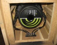
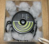
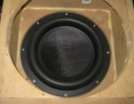
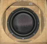
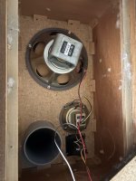
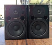
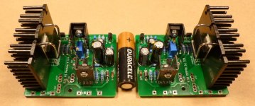
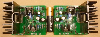
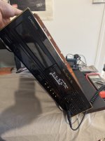
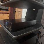
So, I would like to run inverted drivers in a slightly tweaked version of this enclosure, something similar to the image attached to the end of this post.
These are the M4.18 subwoofers, made by MM-Acoustics in Europe, a Macedonian outfit headed by Marjan Milosevic, a regular poster and long time member over on SP.

My god, they look absolutely amazing, so business like.
This is the look I am going for.... They are absolutely badass indeed.

Anyway..... enough airy introductions, and down to business then !!

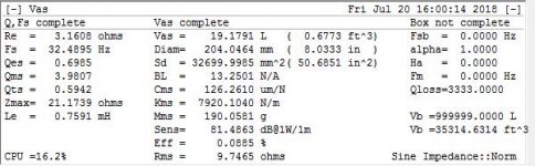
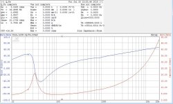
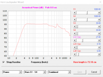
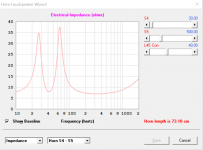
Hog Scoop Hornresp input parameters

First things first, I decided it would bee prudent to simulate a hog scoop with a driver in it's normal orientation first..... Cone side out.
This was to bee my baseline sim, a benchmark to work from before l went tweaking the original design.

And staight away I ran into problems.

For a start, the speakerplans.com forum isn't very active these days..... And a huge amount of information from back when it was is just lost.

Many externally hosted images are not there any more, there are many dead links, hosted plans, you name it, gone !!!
It didn't make my research easy but I did what I could with what I had.

That said, there were many helpful and informative threads to bee found amongst all the bickericking and the politics in the Scoop subforum.

So, lets discuss what was available to find on the net first.... Multiple posts regarding the Hog Scoop hornresp input parameters were scattered around the web....
And just not consistent.
I was hoping to pull some numbers out of a post or a sketch somewhere but straight off the bat, numbers and posts were conflicting.

Unfortunately, I found more than one set of digits, which only infuriated and confused me even more.

Here are the most posted (and reposted) HR Hog Scoop numbers, I beleive they orignally came from Staiper, and these ones were the most common to bee found online,
copy and pasted in at least 4 different places, so I am inclined to stick with the guy who originally penned the Hog Scoop design. He did create it after all.

Stipe Hog Scoop

S1 = 750
Con = 112.8
S2 = 1062
Con = 42
S3 = 1770
Con = 51
S4 = 2544
Con = 47
S5 = 5700
Vrc = 0
Lrc = 0
Fr = 0
Tal = 0
Vtc = 49456
Atc = 86

Re-posted by bitzo,
https://forum.speakerplans.com/forum_posts.asp?TID=16974&PID=214119&title=database-simulation#214119

toastyghost,
https://forum.speakerplans.com/forum_posts.asp?TID=16974&PID=727583&title=database-simulation#727583

Bee,
https://forum.speakerplans.com/forum_posts.asp?TID=72607&PID=828911&title=hog-scoop-drivers#828911

and salzburgsound system

The next set of input data numbers to bee found were these ones you see below.....
--------S1 = 750
Par = 0.10
S2 = 750
Par = 200.90
S3 = 1700
Par = 61.00
S4 = 4740
Par = 12.10
S5 = 5700
Vrc = 0
Ap1 = 0
Lrc = 0
Lpt = 0
Vtc = 37060
Atc = 1453.10

Posted by Heathrow B Line
https://forum.speakerplans.com/foru...=901195&title=scoop-hr-reference-guide#901195

epa

Freddi

And one more, with newer and revised numbers, taken from a post by user "epa" from 2014.

S1 = 750
Par = 0.10
S2 = 750
Par = 187.90
S3 = 1700
Par = 52.00
S4 = 4740
Par = 12.10
S5 = 5700
Vrc = 0
Lrc = 0
Ap1 = 0
Lpt = 0
Vtc = 41091
Atc = 2210.00

Posted by epa

Other than these three sets of input parameters, I did find a few posts by Staiper himself, modeling the Hog Scoop as an exponential horn,
in quite a numerically sparce fashion I must add.... It would seem this stripped down form of modelling came from Rog Mogale himself.
i will link after the following
---------->
Staiper Exponential Hog

S1 = 750
S2 = 5700
L = 260 EXP
Vtc = 36000 (with driver)
Atc = 1000

https://forum.speakerplans.com/forum_posts.asp?TID=8887&PID=218876&title=hog-scoop#218876

Staiper Exponential Again....

S1 = 750
S2 = 5700
L = 257 EXP
Vtc = 37000
Atc = 9000

https://forum.speakerplans.com/forum_posts.asp?TID=8329&PID=77534&title=tapped-horn-design#77534

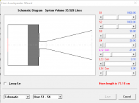
And finally....... An attempt at simming a Hog Scoop by the man, Rog Mogale himself.

S1 = 750
S2 = 5700
L = 240 EXP
Vtc = 35000
Atc = 890

https://forum.speakerplans.com/forum_posts.asp?TID=8329&PID=77097&title=tapped-horn-design#77097

And here is a good thread full of interesting tit bits where Rog discusses his exponential scoop modelling methods with others.
https://forum.speakerplans.com/forum_posts.asp?TID=8329&PID=77097&title=tapped-horn-design#77097

A must read for anyone into this line of work.

Annd..... Time to take stock.

All my research and reading paid off, but unfortunately I still feel I do not have any concrete numbers for a Hog Scoop simulation binge.

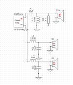
So, I took some time out and drew up a scaled plan of the Hog, just enough to play with.
it gave me a much more definite idea of the direction I asm going in, speaker boxes ofthen quite literally build themselves as the project goes on.
Solutions are often just so obvious when you have the material object taking shape before your eyes.

And measurements can bee taken from the plan and scaled up to something that resembles real world numbers.
(Drawing attached)
And just to bee sure, I am going to get my hands on one side panel first, (18mm sheet board 986 x 950mm) and draw it out @ a life size scale on the floor.

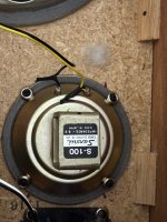
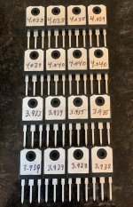
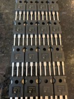
Drivers for this design

I currently have 2 B&C 18TBX100 (4 ohm) belonging to a friend to use for the first 2 boxes and am debating which drivers to buy for the rest.

Quite likely B&C as well, I like the power handling (1500w) and price of the 18SW1OO.
When given the option, I usually buy 4 ohm versions of any driver when I can.
They can often bee had for the same price as their 8ohm equivalents but sometimes not. Sometimes they are just more hassle to obtain but I do make an effort to
use 4 ohm drivers when ever I can.
I am also open to other brands, I do know I need a certain type of driver to do well in these boxes and if one particular driver turns out to bee
especially suited to the task it will surely bee strongly considered.

So far, everything is going well.... The only other uncertainty I have right now is the design of the rear chamber.
I am not sure exactly how it will end up but I am confident the design (and build) process will answer it's own questions if and when they arise.
More on that in detail later.

Okay, I think I have written enough for now.... Any advice and criticism is warmly welcomed.
Please feel free to join me on my journey of discovery and don't bee shy to interject or comment if need bee.

M4.18 MM-Acoustics.jpg


K - Scoop.jpg
  • Like
Reactions: Rik_bS

Tannoy PBM 8 upgrade?

Hi everyone.
I have a passive home studio system with a pair of older (well maintained) tannoy pbm 8, along with an equally well maintained pair of yamaha ns 10, and i’m trying to find the most appropriate upgrade on the tannoy pair.
Passive, 8’’ woofers, similar frequency response and not far more expensive. And of course i would prefer older used stuff. Not necessarily studio grade. Just different and maybe better than the pbm 8.
Any suggestions?
I guess older yamaha passives 8’’ must be pretty similar to the ns 10 (even if they are one of a kind in a way…).
Dynaudio passives are the first that come to mind. But i guess there are more, maybe cheaper and maybe better.

Thanks.

Tokin DEFISIT Duo Capacitor Output Stage Amplifier

Here is my latest Tokin SIT amplifier. It is a DEFISIT amp (Depletion Enhancement Follower SIT) output stage based on Nelson's First Watt SIT-5 output stage. Diyers more knowledgeable than me picked apart what information Nelson provided in his SIT-5 owners' manual (https://www.diyaudio.com/community/threads/first-watt-sit5.418023/), and I rode on their coattails and came up with this version.

My build is only the output stage, and it incorporates the duo output capacitor arrangement which can be tweaked to adjust the amount of current amplification that the mosfet part of the DEFISIT push-pull output contributes to the total current amplification. This is a departure from the regular DEFISIT amplifier, where the SIT and mosfet both fully contribute to the total current amplification.

Here are a couple of LTSpice simulations. I did many simulations, but these two are what I based my design on. I chose -47VDC for one sim since I intended to build it using one of my existing amplifier chassis and power supply. I chose the -63VDC for the other since that is a reasonable voltage that will take advantage of the power capability of the THF-51S and still keep the power supply voltage reasonable for capacitor voltage and heat sink heat dissipation.

As shown in the simulation results (47VDC power supply and 2.0A Iq), the measured current through C4 connected to the SIT drain was 361mA peak, the measured current through C7 connected to the mosfet drain was 150mA, for a total of 511mA. As a check the current measured through the speaker, R8, was 509mA - close enough. So the contribution of the mosfet was 150mA/511mA = 29%.

I have not included the LTSpice screen shots of power output but the 8 Ohm power output was nearly 23W at 1% THD and 4 Ohm power output was nearly 40W at 1% THD.


63VDC PS 2A 8R 1Watt:

Tokin DEFISIT Duo Output Cap OS 63VDC 8R 1W.png


63VDC PS 2A AC signal current through C4, C7, and 8R Speaker:

Tokin DEFESIT Duo Output Cap OS 63VDC Mosfet-SIT Output Current Ratio.png


47VDC PS 2A 8R 1Watt:

Tokin DEFISIT Duo Output Cap OS 47VDC 8R 1W.png


47VDC PS 2A AC signal current through C4, C7, and 8R Speaker:

Tokin DEFISIT Duo Output Cap OS 47VDC Mosfet-SIT Output Current Ratio.png.png


As mentioned I decided to build the 47VDC version. The chassis and power supply is from my BAF2015 Amplifier - A SIT Mu Follower Revisited With Feedback (https://www.diyaudio.com/community/...t-mu-follower-revisited-with-feedback.408193/). The power supply is CLC, comprising 2x22mF - Hammond 156B - 2x22mF, and an Antek AS-3218 transformer per channel for full dual mono construction.

I put together a PCB design and sent it off to JLCPCB for fabrication. In addition to stuffing the PCB once I received it, I also changed the CLC filter from V+ supply to V- supply.

THF-51S DEFISIT Duo Output Caps Right Channel PCB.jpg


Initial power-up and subsequent Iq and SIT Vds adjustments went smoothly, and Iq and SIT Vds were stable.

Next up was testing with an 1kHz signal and distortion measurements. Unfortunately when powered up with an AC line powered 1kHz oscillator connected, the amp immediately blew the powerline fuse. So it was trouble shooting time. After checking the schematic and pcb, checking that the input capacitor was not faulty, and not finding any visible ground shorts with the meter, I was baffled.

I knew that the issue was mostly likely a grounding problem and that it only manifested itelf when an input device was connected to the amplifier. Luckily a thought came to me fairly quickly - when I changed the CLC filter from V+ to V- supply, I forgot to move the power supply connection to safety ground on the CLC filter board. The correction was made and success. Only one fuse was permanently damaged.

The dim bulb tester came in handy here as once the fuse blew, the dim bulb tester went in and I was able to probe around with power and not blow anything. In addition to using it during trouble shooting, I always use it for first power-up testing of power supplies during various stages of construction and first power-up testing of audio circuits.

As for the amplifier supply not shorting with no input device connected but shorting with an input device connected, I gave it some thought. The power supply was for V-, with V- from the supply connected as power to the amplifier circuit. V+ from the supply was connected to the amplifier circuit board as ground. The V- from the supply was ground in the previous amplifier but I forgot to change it so it was now incorrectly connected to chassis safety ground. With no input device connected to the amplifier circuit, the power to the amplifier board was floating. Although the V- was also connected to the chassis safety ground and to the powerline/IEC ground, there was no other direct connection to V+, so no short. The live from the powerline/IEC was connected to the transformer primary, which was isolated from the transformer secondary. Also the speaker and input jacks were isolated from the chassis. So with no complete direct connection of V- to V+, the current can only flow through the audio circuit. The chassis was connected to V- but there was no path for the current to flow from the chassis to power supply V+.

When the oscillator was connected to the amplifier input, the circuit was completed, current flowed, and the fuse blew. That was because the oscillator was AC powered and had a safety ground connection. So the oscillator line safety ground connected to the oscillator power supply ground, then connected to the oscillator signal ground, then connected to the amplifier signal ground, then connected to the amplifier V+. The oscillator safety ground is also connected to the amplifier safety ground through the line ground, and the amplifier safety ground is connected to amplifier V-. The net result was amplifier V+ and amplifier V- were connected together - a short circuit. There was a CL60 thermistor at the amplifier power supply ground connection. That would have limited the short circuit current: 47V/10R = 4.7A. Fuse was 2.5A slow blow.

I have swapped power supply polarity before but had always remembered to switch the safety ground connected, until this time.

So always be careful. Electricity can kill.

THf-51S DEFISIT Duo Output Caps Right Channel Build.jpg

Hi from Denmark

I'm coming from playing music, then studying electronics and then sound design.
Along the way I was fortunate to meet an awesome dude who got me into diy audio after i heard his horn speakers.

Got some diy TL's and 3D printed Bill Waslo meh's with 12" bass port cabs. Also a pair of Genelecs 8030.

I'm hoping to upgrade my bass situation in the near future. 🙂
  • Like
Reactions: Speedysteve7

Hello there from Austria!

My name is Michael and I have been visiting this forum sometimes before an really enjoyed reading about all your cool projects.

HiFi is my favorite hobby.

Two years ago I startet doing some projects on my own instead of just fixing vintage hifi stuff…mainly from the 70s and 80s.

Right now I am looking for a good solution to drive my vintage Grundig active speakers…I will post about that in the existing thread.

Thanks for letting me take part in this great community!

Greetings
  • Like
Reactions: ndiyer

CCS in anode vs CCS in cathode?

What is the difference in the end between say using a DN2540 style CCS at the anode vs a LM317 CCS at the cathode? Isn't the end-game objective the same to fix the DC current? Does the anode CCS also provide a higher impedance load benefit, whereby the cathode CCS would only fix the current but not ease the load? What if my driver stage currently uses an interstage transformer load, could adding a CCS above anode choke really improve things beyond a choke alone? Basically if you had a driver stage that had a interstage anode and cathode resistor. And you wanted to add a CCS, would you add it at the cathode or anode?
  • Like
Reactions: Miniwatt

Best cabinet plans for Markaudio Pluvia7HD

Hello

Looking for good cabinet plans for Markaudio Pluvia 7HD

By googling i did find this one https://frugal-phile.com/boxlib/pensils/PensilP7HD-260520.pdf but its not on offical frugal phile site you can only find it by direct link. is it still ok for PLUVIA7HD.2 GEN ?

Also considering plans from:

https://sites.google.com/view/low-end-diy-loudspeaker/diy-tqwtml-voigt-pipe-with-damp-duct
https://sites.google.com/view/low-end-diy-loudspeaker/diy-tapered-wave-tube-with-damp-duct-twtd

Does anyone know any other plans for Pluvia7HD?

Thanks

symphonic-mpd

The content of this thread is my personal opinion and does not represent performance based on objective metrics.


Information about symphonic-mpd, a CRAFTED LINUX for Raspberry Pi4.

It has been developed to target audiophile who want high quality music playback on I2S output.

Official Forum
symphonic-mpd

If you are interested, please ask your questions in this thread.

In order to use the SD images of this distribution, you need to join the official forum.
If you would like to join, please email me below with your handle name.

symphonic.mpd@gmail.com
kubotayo@jcom.home.ne.jp
mark.create@gmail.com

img_0232.jpg


img_0230.jpg

Troels Gravesen AtiRi

So, the kit of the AtiRi has been bought and I am thinking of pumping it up and make a Kawero Classic clone (kind of) out of it.
But I need your help regarding the bass segment.
My plan is simple, take the two way AtiRi (15Liter) and put on a 40Liter bass reflex cabinet. untill now same as Kawero.
The woofer I will use for the 40Liter is the 10inch Faitalpro RS350. it will be driven by Hypex Fa501.

Now, I really really want to nail this bass, clean accurate, powerful.
So the following ideas are:
1. 40liter-bass reflex with one RS350 10inch driver
2. 40liter- closed cabinet with one RS350 10 inch driver -infinite baffle
3. 40liter- Closed cabinet with Two!! RS350 10 inch driver

I know its more about opinions and everything is a compromise but it would be great to hear your preferences.

Thanks!
ATiRi2 20241204 20h35m56s.png
Capture.JPG
Capture2.JPG
ATiRi-1 (1).jpg
  • Like
Reactions: matsurus and adason

3-way - port tube placement and braces

Hi all
I'm trying to design a 3-way speaker based on mid-range and tweeter I already have (used in a 2 way speaker some years ago).
I decided to add SB26SFCL38-8 to these 2 drivers in bass reflex configuration. The volume for the woofer will be around 88L with a resonant frequency is 27Hz.
I want create a cabinet with hard plywood 19mm with external size WxDxH 38x55x63 (the height is a constraint).
The cabinet will have a "small room" for the mid and tweeter of about 8L.
The port tube will have diameter of 9,2 cm and length of 22,5 cm
I have 2 main doubts now (may be more 🙂)
1. Where put the port tube. I have not enough space below the woofer do I would like to place it upper. Something like this...

1745836195042.png
1745836229261.png


I also did a try with 2 port of 6,6 cm and 24,5 cm length below the woofer.

1745836314893.png


What do you think is the best solution?

2. How many braces, where to place them and how shape them. I'm not so expert about this aspect.

New member from Berlin, Germany, interested in building a TL-Speaker

I am living in Berlin since 35 years and I am engaged in building speakers privately and professionally since I was 12 years old. Now I want to return to my roots building DIY Transmissionline Speakers. Back in the 70ies I started to build speakers with SEAS drivers, PEERLESS drivers and GOODMANS drivers. But my heart finally fell on KEF drivers and that´s where I want to restart. Let´s see what ideas I get after being involved deeper into the exchange on this forum. Regards, Mark.

Hi from a DIY noob

I was dissatisfied with modern hifi that just was not hitting the spot for me. Was not enjoying lisetening to music. Started buying a few bits of vintage and the magic was there again and these things are so lovely. Cant stop listening to music now.

Nothing particularly high end. A few low power Sansui, 555, 101, 555a 2200, 217II and 317. Got a Sugden A48 MkII and a Naim Nait 1. Got a few different speakers. Spendor BC1, Ditton 44, Linn Kan Mk1, Lin Sara and Meridian M20. Also ended up with a Sondek LP12 that needs some TLC.

I am not experienced with electronics but really interested now and learning by doing. One of my Meridian M20s is not working. I am trying to fix it. I am getting pretty close to working out the issue though. Identified the op amp that is failing. Not worked out why yet. When trying to google for a service manual for these there were a couple of posts on this site asking for the same and that is what brought me here. Looking forward to going on the journey learning about fixing, maintaining and even improving all of this lovely old gear.
  • Like
Reactions: 6L6

For Sale ATC SB76-314SC

For sale a pair of ATC SB75-314S in very good condition and with fresh new surrounds.
They can be used as well to replace the SB75-314SL because they behave and measure equal to those. Just Some better an more linear roll off in the SL. The SL has not a resonance peak more than 12dB below crossover point at 500/600Hz.


Price for the pair will be 450€ + PP fees + Shipping at cost.


IMG_6437.jpeg

IMG_6436.jpeg


IMG_6438.jpeg

Schematic request: Alesis BRC (Big Remote Control)

I looked around and can't find a good place to file this thread, so if I missed something, Mods, please feel free to relocate.

I am about to purchase an Alesis BRC which will (hopefully) control my HD24 [24-track hard disc recorder]. It was originally designed to control many ADAT machines, daisy chained together. ADAT uses SVHS tape for audio recording. Anyway the HD24 is 24 tracks od digital recording onto hot-swappable hard drives. But since access is orders of magnitude faster on the HD than spooling tape, there can be sync issues... (it CAN allegedly daisy chain HD24s to provide 48+ tracks, up to 128 max or something silly like that)

I have the Alesis service manual, and it indicates an appendix for the schematics, but they are not there. It must have been a separate file or insert added at the repair facility. I do have the "confidential" service tech final testing procedures at the end of the copy of the manual I have so it seems to be "complete".

Please have a look around and see if you have one or can point me to an online source. I can't find it anywhere and I was digging pretty deep...

Thanks in advance for any help!

1746220221779.png

Pair of unused bass/mid drivers Audax HM170Z2

Stock clean up: a pair of unused Audax Aerogel dual voice coil 17 cm bass/mid drivers (type HM170Z2)
Bought for a project which was never started (due to other priorities).
The units are packed in the original box and are not broken in.
Price: 170 euro plus shipping (preferably within EU)

Attachments

  • Foto_1.jpg
    Foto_1.jpg
    303.7 KB · Views: 87
  • Foto_2.jpg
    Foto_2.jpg
    230.5 KB · Views: 105
  • Foto_3.jpg
    Foto_3.jpg
    370.4 KB · Views: 106
  • Foto_4.jpg
    Foto_4.jpg
    287.5 KB · Views: 114
  • Impedance Speaker 1.png
    Impedance Speaker 1.png
    34.3 KB · Views: 104
  • Impedance Speaker 2.png
    Impedance Speaker 2.png
    32.5 KB · Views: 96

OPA1656 Phono Preamp: Split from OPA1656 thread

I have an OPA1656 story that may be interesting especially to whomever wants to build the RIAA preamp example in the apps section of the data sheet. I did build that and the slightly modified schemo is attached. I used the attached blank proto board. The Layout is attached. Of the three independent rails on each edge the outside L and R were used for -15V and +15V, resp. The inner two were 0V, center Gnd, branched at power entry at the top. The rails are heavily post-filtered and bypassed and the P/S is external. The DIP8 socket has 0.1uF X7Rs pin 8→gnd, pin 4→gnd and pin4↔pin 8. The enclosure is cast Al/Zn, at 0V and everything “grounded” only via the cable shields to the main preamp. I used polystyrene caps b/c they can be had surplus in 1% values. 000.0mV appears across the 47KΩ non-inverting input load resistors and at rest the finished unit is dead quite.

Now, my turntable is a full-auto linear tracker with internal mute switch used to short the ± moving magnet cartridge coil leads together while lowering onto and lifting off of the record surface. On the maiden voyage of my new external RIAA preamp I turned the system volume down; pressed Play on the TT and once the needle was down, slowly raised the volume to take a listen. Sounded GREAT. Turned-up the volume to let it “burn-in” while I did something else.

Once the side had finished I heard a tremendously loud POP-THUMP (tonearm lifting) and seconds later another very disturbing THUMP-POP (tonearm returned to rest). The mere action of the mute switch shorting and un-shorting the cartridge leads was causing a huge transient at the RIAA output. The 1656 just went berserk! “Somethings wrong and I have to use all my horsepower to fix it right now!”.

Of the op amps in my collection the massive misbehavers are the OPA1656, the LME49990 and the OPA1612. The completely docile op amps are the OPA2604, the OPA627, the OPA2107, the LM4562/LME49720 and the OPA2134. Those are fine.

Long-winded question for anybody is what’s the diff between these two groups of op amps that allows for such infinitely different behaviors in this very, very common circuit? In my case, my TT happens to have a mute function = I’m denied use of the 1656.

Attachments

  • Like
Reactions: KT315A and sonicles

NSM4202A LED Display Module Replacement for Philips / Sony CDM Transports

I have an old Krell MD-2 CD turntable, and (among other issues) several segments have gone out on the LED display. After looking around online, I found one person in France that had built a replacement, but details were kind of scarce, so tried to reverse engineer my display module based upon the tidbits of information that I was able to uncover.

After hooking it up to a scope, it appeared to use SPI (keep in mind that I'm not very smart), but I just got rubbish when I created a small Arduino program to read the data, so I traipsed through the available LED drivers on DigiKey, and came across the MM5450 as one of the very few chips that didn't require I2C. Upon reviewing the data stream again, it appeared to fit with what was required to drive this chip. Anyway, I did the best that I could to guess the pinout of my existing display board (it uses an unmarked glob to hold down the IC die), and was able to reconcile it with the MM5450 pinout, so I made up a board, bought some parts, and tried it out. It appears to be fully functional, so I thought that I would share it here so that others can create a replacement for themselves as necessary. I'm kind of hoping that since this hardware is over 25 years old (and apparently out of production for quite some time) that Philips won't mind too much the publishing of plans for a replacement...

Anyway, here goes with the information:

Feel free to use this information however you wish, so long as you don't make anyone pay for it. I don't care if you charge someone to assemble a board for them or something (it's none of my business), but the information should be kept in the open. I abhor GPL-like licensing, but I do expect you to not be a turd.

I am just a hobbyist (and a really unintelligent one at that), so I do not make any representation that information is accurate, safe, or suitable for any purpose, even a purpose that may be implied by the information. In other words, I did the best that I could, it worked for me, but it's not on me if you hurt yourself or start a fire or something.

I have the board shared at OSH Park (https://oshpark.com/shared_projects/P3nC9ISV) for convenience. I make nothing from this link or design (AFIAK), and I don't care from where you order your board.

BOM:

  • U1 - Micrel MM5450 (PLCC-44) LED Display Driver
  • DS1-DS4 - Kingbright ACSA03-41SGWA-F01 7-Segment Common-Anode LED Display (Green, other colors probably available)
  • D1-D2 - 0603 SMD LED (Green for use with the specified green LED digits)
  • R1 - 7.5kOhm (or higher) 1206 SMD Resistor (controls brightness)
  • C1 - 1000pF 1206 SMD Capacitor
  • J1-J3 - 0.1" header system of your choice

Electrical Schematic:
View attachment NSM4202A Schematic.pdf

Front of PCB:
NSM4202A Front.png

Back of PCB:
NSM4202A Back.png

Gerbers for PCB:
View attachment NSM4202A.zip

DipTrace Schematic and Board Files:
View attachment NSM4202A DipTrace Files.zip

Why would an amp designer intentionally use different OPT impedances for Left vs. Right?

(I posted this on the AK forum, and so far nobody can give me a good answer, so a gold star to the one who can . . .)

So I'm thinking for my next tube amp build I would really like to do a little integrated 6AQ5 push-pull, so I was researching some of the greats, and apparently the Voice of Music 1404 integrated amplifier (581 console) really stands out as a super performer based upon many comments I have read.

I have a one page schematic, as well as a pdf copy of the SAMs posted below for the model 581 console, which used essentially the same chassis. It very clearly shows that the left and right output transformers are different- one has a primary impedance of 5700 ohms, the other is 7000 ohms. This is confirmed in the schematic, which indicates a different DCR for each primary (325 vs 340 ohms per side). These are not two "alternates" or an accident, this is a deliberate design choice to use a different load line (but same operating point) for left versus right.

Does anyone know why this would be done? I have never seen that before.


1746237489386.png


BTW I think the super cheap 6AQ5 (essentially a 6V6 in a 7-pin peanut) will be very fun to play with- guitar amps are using them like crazy but still seem to be quite overlooked in new audio builds.

Attachments

Apos gremlin headphone amp as preamplifier

I am considering how to improve my system for a modest cost. At present, I have no preamplifier. (I am using and amplifier with a volume control). A possible cost-effective solution might be the gremlin headphone amplifier. The problem I am attempting to overcome is the fact that the gremlin uses strictly balanced input and output. All my components use unbalanced cables.
I at present I'm unable to discern exactly what is needed to convert an unbalanced input into the gremlin and output an unbalanced output from the gremlin to the amplifier.
Would the following cable work for input:
https://www.amazon.com/TISINO-Stere...l+rca+to+male+xlr+cable&qid=1746337003&sr=8-3

Would the following cable work for output to the amplifier:
https://www.amazon.com/gotor-pin-Ma...+to+male+xlr+cable+4+connector,aps,184&sr=8-3

Thanks in advance for any comments.

Modelling a CHN-110 BVR in Hornresp

I've been learning Hornresp recently and was interested in designing a BVR for a pair of MA CHN 110's. I'm reasonably new to speaker modelling so would welcome feedback. I think what I've done so far seems reasonable in theory but I'm sure there are some variables I haven't accounted for.

I'm undecided if I will build this as yet - I'm enjoying the driver (in a Pensil) and would be curious to hear other configurations. Especially something that may add a little more 'punch' in the mid-bass.

I've also attached a quick drawing from fusion, the dimensions are no longer correct as I've changed the model since, but wondered if this basic layout for construction might work?

Matt

Attachments

  • CHN 110 schematic.png
    CHN 110 schematic.png
    43 KB · Views: 173
  • CHN 110 BVR power.png
    CHN 110 BVR power.png
    65.4 KB · Views: 160
  • CHN 110 BVR imp.png
    CHN 110 BVR imp.png
    52.9 KB · Views: 168
  • Untitled v2.png
    Untitled v2.png
    107.4 KB · Views: 165

Passive Speaker Crossover PCBs GB - Any Interest?

Hi All,
I'd like to gauge interest in a Group Buy of PCBs for passive crossovers for speakers. I've made some for my own use and am happy with the outcome. I've attached some pics of one that I made. I can post more as I have 4 made so far. I am considering laying out generic type PCBs for 2-way and 3-way crossovers. The PCBs I got were from JLPCB which were incredibly inexpensive. With the current tariff climate, the shipping has gone up considerably because Hong Kong is no long shipping packages but even so, prices for the PCBs would be pretty cheap. Feel free to post so I can get an idea of level of interest and I'll take it from there.

Attachments

  • DSC_0006.png
    DSC_0006.png
    1.8 MB · Views: 29
  • DSC_0022.png
    DSC_0022.png
    1.5 MB · Views: 28
  • DSC_0025.png
    DSC_0025.png
    1.3 MB · Views: 29

Apollo Light Drive

Light fantastic​


“The P1 power amplifier requires a super clean high current power supply to turn the low voltage line level music signal into hundreds of watts of output power. To do this, Siltech designed the Apollo Light Drive. A super-strong AC-powered light source is used to drive a photo-electric cell, giving a totally noise-free, galvanically isolated DC output. This then drives the amplifier’s output stage, keeping it absolutely immune from mains-born distortion. The idea behind this is not new, but its execution in a high powered amplifier is extremely challenging. The result is ultra-clean, low distortion power – and lots of it.”

Has anyone tried DIYing this concept?

IMG_0844.jpeg


https://www.siltechcables.com/saga-amplifier-system/

ZEN Amplifier Mini with IRF610 as Headphone Amplifier for 32 Ohm

The ZEN Amplifier concept is simple. But it works great.
Here is such an amplifier but with less current and uses IRF610 as MOSFET.
It makes a simple and sweet headphone amp.

Building shouldn't be difficult.
The heatsinking it takes is not so much.
There is some THD, but it is mainly 2nd harmonic.
So, it would be good listening.

The amp is designed for 32 Ohms headphones.
For other impedances it may need tweaking to make it alright.

ZEN Mini Headphone Amp_19.jpg
  • Like
Reactions: decramer

Scanspeak D7608-9200 mid dome disassembly tips and other info

* Disclaimer - Perform the following procedure at your own risk. Not responsible for damage to your own driver !!! *

I finally decided to take a chance at removing the mounting flange on one of my D7608-9200 dome mids. I'm documenting this so others can attempt the same. Again, please use caution doing this by yourself. This procedure is reversible if you're careful.

To start with, the flange is held onto the driver assembly with very tenacious contact adhesive. Do the following to pull the driver element away.

I started by grabbing the flange with the dome facing away from me, using two thumbs to push / bend the flang away from the magnet, little by little, opening the gap up. Once you start weakening the adhesive bond at the gap, working your way around the flange, you'll notice it starting to gradually separate, until the motor assembly can be completely pulled away by hand, holding onto it by the outer flange and motor / magnet assy edge. I dont recommend prying between the flange and inner edge, as this clamps the entire dome and motor together - you can damage the inner thin plastic ring which holds down and terminates the dome surround to the motor. Also watch the 3 clips on the side of the dome assy, which can break fairly easily when prying away the flange, especially at first as you start bending away the flange for the first time.

This whole process only took a few minutes to accomplish, but removing the left over adhesive was the hardest part, not having identified a suitable solvent to simply loosen and remove the glue. I ended up using some naphta (lighter fluid or BBQ charcoal starting fuel) to scrape away the bulk of the factory contact adhesive. This took about 30 minutes to do. DO NOT USE aromatic HC based solvents, as it will attack the plastic, which appears to be made from ABS.

If you're careful not to damage the flange upon removal, it can be reattached later on with some 3M weather strip adhesive or other contact cement.

Sorry for the lousy pictures.

- more D7608 info here to follow soon !

Attachments

  • 20240322_231740.jpg
    20240322_231740.jpg
    540.8 KB · Views: 332
  • 20240322_231817.jpg
    20240322_231817.jpg
    558.5 KB · Views: 308
  • 20240322_231825.jpg
    20240322_231825.jpg
    410.7 KB · Views: 311

Introduction

I am a maker and a tinker. At the school where I work, I also maintain a makerspace. Since I was 12 years old, I have been creating all kinds of electronics, from mixing consoles and amplifiers to microcontroller-controlled devices. Recently, I have been working with Arduinos, micro:bits, and Raspberry Pis. I teach kids how to program Lego robots. Additionally, I educate young people on 3D design and printing. At school, I also teach CNC programming and manufacturing, as well as 3D design and CAM. At home, I have my own lab where I always need some new gadgets. 😊
  • Like
Reactions: stv
Projects by fanatics, for fanatics
Get answers and advice for everyone wanting to learn the art of audio.
Join the Community
507,765
Members
7,887,520
Messages

Filter

Forum Statistics

Threads
406,183
Messages
7,887,520
Members
507,765
Latest member
Coreque