2.5 speaker. Separate or single chamber for woofers?

Hi,

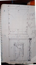
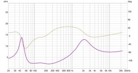
I am modeling with VituixCAD some 2.5 speaker. I do have couple of woofer measurements at hand, but the simulation shows that the low end of bassreflex box will be exactly the same if I put 2 woofers lets say in 10L box tuned to 60Hz or separate them into 2 x 5L chambers tuned to 60Hz. The only difference is 2 vents are mandatory then.

Somehow my guts feel that separate chambers will have better isolation of lower woofer diaphragm from mid freq inner bounces of upper woofer and lower overall acoustic crosstalk between them. But on the other side somehow have a feeling that bigger single box has some advantages... But cannot name them. 😀 Maybe none?

So, what would be your choice in every choice?
1. Two separate chambers or single?
2. In case of single chamber and single vent - the best position is probably in the same distance to each woofer? Does it matter?
3. In case of 2 chambers or single chamber with two vents - do they need to be tuned a little different not to have the same resonance?
4. In case of 2 vents - do they need to be in identical position to their relative woofer? If the distance of the vent exit from woofer cone is 5-10cm different between each woofer-vent pair - it can be measured, but can it be heard with ears?

Opinions and facts are welcome. Thank you!

Hello diyAudio

Hello everyone. I've been interested in audio for quite a few years now and made a few DIY projects already. I found out about hornresp later learning about this forum. The hornresp app is extremely useful and full of features. I want to learn more about it and share my thoughts on different audio projects with other people here. I'm excited to become the part of the community.

Here's BP1Fanatic's 55Hz 1/4 wave tapped pipe as the lower end of an E-drum speaker

GRS12PT - sealed box on top with old Beta8CX/APT50/APT3 - series network 3mH/30uF from tapped pipe to 8CX woofer - 0.47mH on 8cx woof - 3.3uF.0.3mH on APT50 - some series attenuation w. some C bypass on CD.

Source = Flamma Drum/Loop mini pedal /Fosi TPA3255 mono amp.

Don't know what forum it fits ;^)


Login to view embedded media

Attachments

  • 40 liter tapped pipe for GRS 12PT rough sketch 1600.jpg
    40 liter tapped pipe for GRS 12PT rough sketch 1600.jpg
    221.4 KB · Views: 39
  • CUBO AND 55HZ TPPED PIPE RESPONSE WITH PYM1298 1600.JPG
    CUBO AND 55HZ TPPED PIPE RESPONSE WITH PYM1298 1600.JPG
    573.6 KB · Views: 38

Harman Kardon HK870

HK870 Amplifier section may have blown outputs or blows fuse!
This is the case of a customer complaint ...
These days outputs are scarce and when available, they come at a premium price. Do I want to take a chance blowing or shorting my new transistors just by replacing them and see what happens?? No!
Since mid 1980's my instruction to my technicians have always been, make sure the amplifier driver stage all the way to its input stage (differential is any) is working good without installing output transistors. That understanding among the early days technicians and service engineers still holds true, just as anyone here agrees that the first order of business in any electronics repair is to make sure all essential power supplies are working properly.
In order to verify and troubleshoot the HK870 amplifier section, one needs to take some simple step. Here it is!
If you have any suggestion, I would like to hear it.
HK870_amp_service_mode.png

Sony Bravia TVKDL-40NX710

My sony TV is having an audio problem it shows a constant fast blinking green LED.
I have removed all the peripheral equipment and pulled the HDMI’s
Removed the smartcard
Powered down the TV for 3 minutes
Reapplied main power
Picture and flashing green led IMMEDIATELY return, normal video available
Sound adjust bar visible on screen in position Min
Increased the soundlevel using remote, audio is heard but as soon as remote sound button is released the volume automatically slows to MIN again
This is repeatable

Hold TV power OFF on remote for 5 seconds, TV turns off, RED LED is ON, GREEN LED is now off.
Turn TV back on using remote,
Reported problem appears again.

Any suggestions?
The problem started after watching Apple TV PHOTO’ via HDMI and having the Apple TV sound in MUTE

I'm a returning member after a long hiatus

Hello all,
Returning member. Haven't posted here in probably 10 years. Looking forward to coming back. Many questions I have about audio as I continue to improve my system; many decades in the making now.
Some background information:
Have been an electronics hobbyist since I was 5 years old. Main interest is in amplifier designs and speaker building, and I have built many examples of both throughout the years.
Professionally, I have been working in the semiconductor industry for 27 years now, first as a test engineer, then as a validation engineer, and most recently as an analog designer.

For Sale Remix cap, Audio Professor, Mundorf, AN, vFET

For sale:
  • Remix capacitor 0,1uf 400v - 40$ / 100pcs new
  • Remix capacitor 0.1uf 600v 50$/ 100pcs new
    IMG_7985.jpeg
    IMG_7986.jpeg
    IMG_7788.jpeg
    IMG_7787.jpeg
    IMG_7622.jpeg
    IMG_7580.jpeg
    IMG_7180.jpeg
  • Western Electric D-168574 16uf 120VAC $ 400VDC - 1000$/ pair
  • Western Electric 4600uf 30v - 90$/ pair
  • Audio Prosessor Super Linear 47uf 600v NOS 270$/ pair
  • Vfet Tokin THF 51 used 70$/ 2pcs matched pair


IMG_7483.jpeg


IMG_7888.jpeg
IMG_7784.jpeg

Attachments

  • IMG_7983.jpeg
    IMG_7983.jpeg
    404.2 KB · Views: 63

NAIM NA322 MM phono board

Hi! I have traced the Naim NA322/4 MM phono board PCB layout from some photos that I found online. I didn’t find any schematic, but there were enough pictures and some descriptions so that I could identify the parts.

Anyway I have some questions left:

1. Can anybody tell me if I have identified the transistors correctly? I am not absolutely sure which of the 10 transistors are ZTX384 and which are ZTX214.
It was hard to tell this from the pictures. Unfortunately I don’t understand the circuit enough and don’t have enough background knowledge to really be able to figure this out logically.

2. Is the polarity of the tantalum caps correct?

3. I can use BC560 instead of ZTX214 and BC550 instead of ZTX384, right?

4. Do the transistors have to be matched? And which have to be matched?

Thanks so much in advance!

Attachments

  • NAIM NA 322-4 PCB.png
    NAIM NA 322-4 PCB.png
    107.1 KB · Views: 2,443
  • na322-4 1.jpg
    na322-4 1.jpg
    648.1 KB · Views: 1,909
  • na322-4 back1.jpg
    na322-4 back1.jpg
    678.8 KB · Views: 1,721
  • na322-4 2.jpg
    na322-4 2.jpg
    192.5 KB · Views: 1,797
  • na322-4 3.jpg
    na322-4 3.jpg
    138.4 KB · Views: 1,667
  • na322-4 4.jpg
    na322-4 4.jpg
    139.1 KB · Views: 1,104

White Cathode Follower - Cathode bypass capacitor question

Hi folks,

I have been searching for an answer to the following question:

What is the purpose of a cathode bypass capacitor in a White Cathode Follower buffer?

My rather limited understanding of tube-land would indicate that a cathode bypass capacitor is employed when the is a need for gain augmentation and/or output impedance reduction.

If I remove the cathode bypass capacitor in the following circuit, would I need to pay attention to any other component values?

1734170779668.png


My goal is to mostly drive low impedance cans.
Specifically, a 38Ω load (Sivga Luan pair of headphones).
My higher impedance cans will be driven by my other amps, so I don't really need for this Morgan Jones mini-tube headphone amplifier to be compatible with cans above 60Ω.
------------

Anyway, back to the original questions:

A. If I remove C3 completely, do I need to consider altering any other values in the circuit in order to not upset the balance of the WFC?
B. What's the 'mystery magic' of having a cathode bypass capacitor in what's essentially a unity gain buffer?

With respect,
Nick.

Head Unit Less Wiring Review

Hello, first time posting. I am looking for a review of my car audio wiring without a head unit, any help is appreciated,
  • Streamer: WiiM Mini
  • DAC: Schiit Modi+
  • DSP: PRV 2.8x
  • 4 Channel Amp: Morel MPS 4.400
  • Mono Amp; JBL A600
  • Fuse Block: amazon link

Motivation: I will be using a WiiM Mini to AirPlay 2 music from my iphone, this connects to my Schiit Modi+ DAC via optical. This is why I have the 2 12v-5v buck converters to power those via USB. DAC->DSP and then to both amps pretty standard from there.

My battery is in my trunk so all runs will be less than 5 feet.

Thanks!


headunit less wiring.jpg

Greetings

Hi everyone,

I’m new here and looking to learn more about vacuum tubes. They’ve always intrigued me, and I’d like to understand how they work, what makes them unique in audio gear, and maybe how to better sort my small collection.

I don’t have much experience with them yet, so I’m here to read, ask questions, and hopefully pick up some knowledge from the experts.

Thanks for having me!

Cabinet construction modifications

Hello!

I am building the SBA 941's from Troels Gravesen and I have a few questions regarding the cabinet construction which there seems to be very little guidance available.

I will be using a CNC machine at my local makerspace for the MDF cutouts and I have therefore made the entire cabinet in Fusion 360. I believe Troels mentioned somewhere that the cabinet construction could be improved. Therefore I have taken inspiration from here and have added another panel inside the cabinet to make the back panel removable for any future adjustments that may need to be made. The panels inside the cabinets also have 5mm deep tracks for extra rigidity and to make the gluing process easier.

The middle panel however seems to have some weaknesses and I suspect that the schematics call for the removal of too much wood which may weaken the internal structure, see the photo provided with the black arrows on the right side:

SBA-941_large.png


Should I make the 130 mm diameter holes smaller, and if so do you have any tips on which size would be optimal - perhaps 105-115mm? The current holes seem to be to close together and the wood in between them gets very thin which I presume may be a bad thing

My other question is that I'm not sure how the front panels should be attached to the rest of the cabinet? Preferably I would like some form of mechanical solution alongside the glue that is to be put in place.

I have added a few other images of the cabinet construction in Fusion 360, hopefully this will give you a better understanding of the cabinet structure - the only part missing is the horizontal piece linking the back panel to the middle panel which I have not added yet. I am open to any changes and improvements that can be made in order to reduce cabinet resonance. I already have quite good cabinet dampening which I hear might be as important as a good cabinet structure, however it would also be nice to have a solid cabinet.

I appreciate any help that you are willing to give, this is my first ever speaker build so I duly apologize if I have made any severe mistakes - I would appreciate if they could be pointed out if so. Thank you in advance and have a nice day!

Link to the official website here: http://www.troelsgravesen.dk/SBA-941.htm

LådaUtanSidor.PNG


LådaUtanSidor2.PNG


SeparataDelar.PNG

polypropylene capacitors

Looking around on various sites : Why is it so hard to find small (so low voltage) MKP (polypropylene) capacitors for audio ?
There are : AC/puls , DC link , motor run, power factor correction, RC snubber, RF and power , RF microwave, suppression film capacitors and... general use .
Which are for audio , in the 4,7 uF to 10 uF range ? ( for input of amps , not for speaker filters)
Sure I can find these Wima red ones and those grey Kemet, but often only for high voltages which makes them very bulky.

Class D TriAmp

I built a TriAmp 5 years ago using class a/b amps and the performance is very good. It has an active filter in the signal input.
I ended up with 28 earth points and I am sure this is why there is no hum.
I am now considering building a TriAmp class D and I am after advice on whether there is a benefit over a single amp as there is using class a/b amps.
I have not built any class D amps yet and if I do I would like to use discrete components.

Impedance graph-How concerned should I be about a 2 ohm load?

This is an impedance graph of my DIY 3 way build.
Two Satori WO24P (8 ohm nominal) woofers in parallel
One Scanspeak 18M 4531 Mid Range
One Wavecore TW030WA11 Tweeter
The final Crossover is all 2nd order stuff. But the impedance graph is a bit concerning. I use Class D Ncore and Purifi amplifiers which are rated for 2 ohms. The load dips to 2 ohms between 200 and 300Hz. It also dips to 2.4 ohms between 75 and 200Hz. Otherwise it looks clean. How concerned should I be?

Attachments

  • Avalanche Impedance.jpg
    Avalanche Impedance.jpg
    83.9 KB · Views: 153

KEF B139 based 3 way identification help

I got my hands on (could not resist bringing home the famous oval driver) these speakers. Doesn't look like DIY (serial numbers on it) but might be a kit.
Can someone help identify what I have?

Attachments

  • PXL_20241016_162928129.jpg
    PXL_20241016_162928129.jpg
    589.7 KB · Views: 109
  • PXL_20241016_162933509.jpg
    PXL_20241016_162933509.jpg
    536.2 KB · Views: 114
  • PXL_20241016_162942139.jpg
    PXL_20241016_162942139.jpg
    593.8 KB · Views: 108

TI Labs’ video course on op-amps

I don’t know whether this has been brought to attention here before, but in 2015, TI produced extensive series of brief video-introductions on op-amp design issues and use, which I hadn’t stumbled across before. So, maybe some others haven’t either. Under the sub-topic titled, “Low distortion design”, there are four videos. Most of which are less than 15 minutes in length. I recommend at least viewing the fourth video there titled, “External Sources”. It goes over sources external to the op-amp which can provoke distortion, such as supply regulator output impedance, input and feedback capacitors and SMD resistors.

https://www.ti.com/video/series/precision-labs/ti-precision-labs-op-amps.html

Large driver ripole tweak...does it make sense?

I am trying to decide between OB and Ripole sub bass for a high SPL 4 way OB.

Crossover will be either around 80hz to two 15" woofers or a little higher, 120-140 to a single 15" woofer.

I am looking at 18" drivers and the main problem with ripoles is cavity resonances at ¼ wavelength. For 18" that would be around 180hz.

What if I mounted the 18" drivers on baffles with 12" holes. That would reduce the chamber depth by 3". The chamber itself could flare out from 12" at 9" depth to 18" at the mouth creating a short horn of sorts.

1. Would it work?
2. Has this been done?
3. Can it be modeled?

This would be the ultimate OB bass foundation.... 4x18" in Ripole configuration up to 80Hz and 2x15" in concrete baffles up to 400hz.

For a stereo pair that would be 8x18" which would equal 2 ½ x the Fostex 31.5" woofer.

1000003516.jpg

Roksan Caspian MK1 CD player disc does not spin

Dear friends.
The CD player came with a rotted tray gear. After replacement I found the disc does not spin at all. When loading a CD or without CD, the motor very slightly nudged.
No service manuals but found out its nearly identical to the CEC CD2100 and has found the service manual for that.
But the document has no voltage markings so I am working blind. What voltage is sensible to test the disc motor so I can rule out the motor is faulty?
Is there a common issue causing the motor to not spin?

Picture is of a similar model (but not mine).

Attachments

  • IMG-20150220-WA0008.jpg
    IMG-20150220-WA0008.jpg
    162.5 KB · Views: 131

Searching for DIY speakers for my Hypex FA123 amps

Hi!

I have lived with a crappy bluetooth speaker for years now and it's time to upgrade. I have realised I do not have the time, place or skill to design a speaker myself but I do have 2 hypex FA123 amps collecting dust from the time when I thought I did!

I was looking to buy when I stumbled across the SEAS King Ro4Y MKIII kit yesterday. It uses the hypex FA253 and they even provide the crossover files etc so you don't even have to design the filters yourself! This was a revelation to me, I did not know these kinds of kits existed!

Since I already own the FA123 I am now searching for a 3-way kit using the Hypex FA123 and where the filters are provided. I feel confident enough to assemble everything myself, I might 3dprint everything even since woodworking in an apartment isn't fun.

What I have found so far is the aforementioned seas kit (If the FA123 is enough for this kit)
https://www.seas.no/index.php?optio...=583:seas-kingro4y-mk-iii&catid=66&Itemid=345

And then @Kwesi in another thread pointed to a german site with a couple of kits that are extremely tempting, if anyone knows anything about this company/these kits please feel free to share! Bliesma tweet/dome mid plus satori wo24p woofer/s.
https://www.ari-acoustics.de/c/opera

I am leaning towards the bookshelf (Ernani) from ari-acoustics or their double woofer floorstander (Nabucco) but would like to know if anyone has any experience with this company and if their kits are any good? And if so, bookshelf or floorstander with my FA123?? What would you choose if we disregard the price? One is designed for the 123 it seems while the other can use the 123 with a small hit do dynamic range?

Any other suggestions in a similar vein?

Only for listening to and recording music/jamming (guitar/piano) in a non-serious way, will be moving soon so the room is not a constant but will be in a living room of probably a smaller size for all to enjoy. I have no idea what kind of speakers I prefer so all suggestions welcome?

Thank you in advance for any suggestions/tips, I would consider any design as long as the filter files are available.

Valkyrie Build: A Compact High-Output Speaker with Smooth Directivity

I previously built Valeria, a compact bookshelf speaker using pro-audio drivers, namely a 6.5" mid-bass and a 1" horn-loaded compression driver. The dynamics offered by this small speaker are impressive, if I may say so myself. It’s currently serving as the center channel in my home theater.

Lately, I’ve been thinking of building speakers with better bass response (a subwoofer will still be necessary though) and improved horizontal and especially vertical directivity. This necessitated using an 8" mid-bass driver, a compression driver that rolls off below 1 kHz, and a horn that can control directivity better than the B&C ME10 I used in Valeria.

The mid-bass driver I selected for Valkyrie is the Lavoce WAF082.00. It has a 2" voice coil, a paper cone, and a cast-aluminum basket. The compression driver, Lavoce DF10.171K, features a 1.75" voice coil and a polyimide diaphragm. As for the horn, I decided to use the RCF HF101, a cast aluminum horn with relatively compact dimensions, which is important to minimize driver-to-driver spacing and consequently improving vertical directivity.

drivers_used.jpg


I designed a compact cabinet with internal bracing that couples to the drivers, making the drivers part of the brace and reinforcing the front and rear sides of the cabinet.

gluing_sides.jpg


The braces were made of 16 mm beech plywood. I attached the braces to the cabinet walls with 3M VHB tape instead of regular wood glue. The soft layer in between acts as constrained-layer damping to reduce resonances.

inside_view_of_braces.jpg


I decided to use a 3rd order LP and 2nd order HP for the crossover along with two notch filters for the compression driver. The crossover frequency is approximately 1 kHz.

crossover_circuit_diagram.png


It’s critical to add absorption material to manage the reflections and standing waves that form inside the cabinet. I lined the walls with felt and placed extra-thick 60 mm pyramid foam on top while leaving enough space for the drivers.

absorption_materials_placed.jpg


Pictured below: Valkyrie standing next to Valeria. Valkyrie’s dimensions are 24 x 42 x 21.5 cm (WxHxD), while Valeria measures 19 x 33 x 22.5 cm (WxHxD).

valkryie_next_to_valeria.jpg


So, how is the sound? By itself, the bass is lacking, as expected. However, as soon as you add a subwoofer to the mix, the missing low-end is filled in, and what you get is effortless dynamics throughout the entire frequency range assuming the subwoofer can keep up with Valkyrie at higher volumes.

In listening tests, it’s immediately apparent that, compared to Valeria, the bass is considerably louder and deeper below 200 Hz. Otherwise, they’re well matched.

The impedance plot looks clean, with the exception of a resonance at around 300 Hz. This appears to be inherent to the mid-bass driver’s construction, as the free-air impedance measurements of the driver show it as well, albeit not as pronounced. The nominal impedance is 6 ohms dipping to 4.4 ohms at 210 Hz.

impedance_and_phase_plot.png


The frequency response is within ±3 dB from 100 to 20,000 Hz (quasi-anechoic measurement). The mid-bass to compression driver crossover frequency is quite low at 1 kHz to help make vertical directivity well behaved. A subwoofer is necessary for good bass response.

quasi_anechoic_frequency_response.png


The horizontal directivity is ±45 degrees nominal, smooth down to 800 Hz. Below that frequency, the directivity quickly becomes omnidirectional. Thanks to the uniform directivity, the frequency response can be equalized without any issues.

valkyrie_horizontal_directivity.png


The vertical directivity is ±35 degrees nominal, and it’s smooth down to a respectable 1200 Hz. As long as your ears aren’t below around 15 degrees of the horn’s center axis, the timbre of the speaker shouldn’t change noticeably regardless of where you sit or stand.

valkyrie_vertical_directivity.png


Last but not least, a complete build video is available below. Please let me know what you think.

Login to view embedded media

Mission 770 freedom crossover upgrade. Advice please

Hi all. I'm new to this group, but it seems full of very knowledgeable people and I wonder if you'd be able to help me out? I have a pair of mission 770 freedom Mark V which I really do love. I keep on comparing them against other speakers and they keep on coming out better however looking at the crossover I see that one of the resistors has got so hot that it's melted the plastic that has attached to so I think there must be some serious need for replacing some of the components such as the resistors and capacitors. Of course these are 40 yrs old and I'm a rank amateur in recognising and decoding the codes on the components so that I can replace them. Anyone to hold my hand through this would be much appreciated. Note I have looked at other posts and there is nothing that answers my questions. .

  1. Do Resistors generally need replacing? Should they get so hot? code ERG 5.8 ER 4R7J -all i can see. I was advised there are differing values present
  2. There is one bipolar cap - code 93-8730 . What is the replacement value?
  3. There is one film cap 4u 7K100 Apparently these do not need replacing?


Many thanks

Attachments

  • IMG_5008.jpeg
    IMG_5008.jpeg
    481.7 KB · Views: 91
  • IMG_5003.jpeg
    IMG_5003.jpeg
    415.1 KB · Views: 66
  • IMG_4998.jpeg
    IMG_4998.jpeg
    384.9 KB · Views: 61
  • IMG_4994.jpeg
    IMG_4994.jpeg
    317 KB · Views: 62
  • IMG_4993.jpeg
    IMG_4993.jpeg
    337.6 KB · Views: 61
  • IMG_4997.jpeg
    IMG_4997.jpeg
    252.4 KB · Views: 60
  • IMG_4996.jpeg
    IMG_4996.jpeg
    316.6 KB · Views: 67

Help with Technics Phono module power supply

Newbie trying to repair
Hi,
I have salvaged tiny phono module from non working technics amplifier. Please see attached picture and schematic. From my newbie perspective it looks like the phono module is fed supply from approx. 0-30v transformer by making it dual (+ve 0 -ve) by adding capacitor and resistors and probably diodes ./? (see red circled parts.)
I have completely discarded rest the amplifier in junk so no longer have it. I only have tiny phono module. It's Schematic (Top corner part of schematic) says it is fed with approx +/-15v).

* earlier I had supplied it with 0-15v single supply resulting in no output. So i thought opamp might be damaged while soldering. I have replaced NJM4562 with ne5532. Will resolder original njm4562 again

My question is
if I have (-15v)-(0v)-(+15v) DC where to connect center 0v from dc supply source ? I guess ground for input and output (pin number 2 and 7) are common. 3 and 6 are signal in. 1 and 8 are signal out.


ph pcb.jpg


Schematic

ph schematic.jpg


Thanks

Vintage SEAS Project

A while back I bought some old Interdyn speakers (made in Aus) which use SEAS H-211 and 25 FE-W with a simple 2nd order crossover.

Sadly one tweeter was toast, the woofers stopped working and the boxes had moisture which made them swell and crumble, so I took the drivers out and decided to experiment with rebuilding them.

The woofers had corrosion on the frames, and the speaker terminals had fallen out of the mounts. I cleaned them up, glued them in place and all was good again. I used Glycerol to recondition the rubber surrounds.

For the tweeter that wasn’t working, I ordered some new domes/voice coils from AliExpress, replaced one and it worked ok, so I put the drivers away thinking I could use them as spares for some other speakers I had.

About a month ago I saw some old empty Philips boxes for sale, which were the right volume for the woofers and with holes roughly the right size, so I thought that I’d have a go at restoring them.

The boxes had a nice veneer but quite thin timber so I added some internal panels and bracing.

I replaced the caps in the crossover, hooked them up and was pleasantly surprised with the sound.

I ordered some ferrofluid for the tweeter that had the new dome and it was better again. So I replaced the voice coil on the old tweeter, and to say I’m impressed with the result is an understatement.

Help with MEH getting over 900Hz

I have been trying to design a 3 way MEH, so far I have built a prototype with a 3d printed throat and MDF horn.

I have been measuring and adjusting different things but can't get it over 900hz.

I modelled it in Akabak with the front chambes in LEM then the ports and horn in BEM

1678723361163.png
1678723399691.png


My BEM sim in Akabak goes up to 2khz (Red is sim, Blue is measured) but in reality it drops off above 900hz ish

Sim vs Measurement.jpg


20230312_124559.jpg
20230312_115927.jpg
20230312_125258.jpg
20230312_125247.jpg


For the drivers I am using four B&C 4NDF34 I have modelled and printed pieces to make them closed back and reduce the rear volume to 0.1L each.

The tape was temporary to hold the rear chamber pieces, I have hot glued the back pieces onto a single driver and am just measuring one at the moment. I did measure with them taped on and there wasn't much difference.

I have measured the impedence of the drivers and compared them to a sim with just a 0.1L rear chamber and the impedence peak is in the same place so I think I have got that part correct. I got a 3d drawing from B&C and modelled it on that to work out the rear volume.

20230222_162122.jpg


The below is my last measurement: (I didn't save it so don't have the data to make a proper graph)

20230312_164806.jpg


I have tried adjusting the tap length and front chamber volume but not managed to get it any higher.

The area at the taps is ~19.33 cm^2 and they are 3.5cm away from the compression driver which makes me think they should be able to play above 900hz easily

Currently the compression ratio is a bit high so I am tempted to forget about going above 900hz and move the mid drivers further away from the comp.

Has anyone got any advice for how I could get the mids to go a bit higher?

Putting a Port with only 0.85 cuft

This could very well be a little bit underwhelming. However, I have a Tropo 10in that I would like to switch since it is an under the seat box. The box has .85 cuft sealed, now that's the problem. I understand .85 isn't crazy, but this subwoofer calls for 1 cuft ported. I've been doing some models on SpeakerBoxLite ( I don't have WinISD) and it seems very promising. However, the port is the current issue; I am not fully set on a design just yet because of port velocity. Also, I think there are better minds on here that might be able to help. I have a 3d printer, so I can build any type of port. The truck that it is in right now is a 2018 Ram, I was thinking of making that long part of the box into the port but I am open to suggestions. If a port came out the back side I would have the ability to have part of the port outside the box. I want to aim for 38hz, since that seems to be the best for a flat line. However, it has 30m/s port velocity. Which I know can affect the performance of the sub.

Attachments

  • Screenshot (2).png
    Screenshot (2).png
    519.5 KB · Views: 54

Digital crossover with an AES in & out for 4-way loudspeaker management?

Less and less people use analog crossovers, including me, so I was wondering about the best crossover devices when wanting to use only AES connections, which are more common in professional equipment. In other words, lets make list of Digital Audio System Processors or Digital Loudspeaker Management Systems that match this description. I will then purchase the most suitable one and then we will see how it performs compared to the traditional Minidsp devices that I have had many over the years. Minidsp of course does not have such AES equipped 4-way product available, otherwise I just might buy that one. 2-way they do have though.

Mofo Amplifier Prasi boards

Completed and ready to use with good parts.Mundorf Evo Silver Gold oil caps,Takman resistor......
Used with top results for about a year(200 hours).Price 50 euro plus 4,90 shipping inside EU!Payment paypal for friends.
If tbe buyer will I can sell 2 Nichicon Super through outlut caps for mofo amp.This are the best sounding from Nichicon.Price 30 euro for a pair!

Attachments

  • 20240606_144532.jpg
    20240606_144532.jpg
    832.9 KB · Views: 333
  • 20240606_144539.jpg
    20240606_144539.jpg
    642.3 KB · Views: 328
  • 20240606_144535.jpg
    20240606_144535.jpg
    767.6 KB · Views: 333

Help with 15" SB Audience sub project

In 30+ years of DIY speakering, I've never considered building a sub before. A recent acquisition of a used pair of KEF LS50 Meta & a simultaneous request from my son to make him something that can give near nightclub levels of modern electronic music (with the LX521-ish clones I made him last year) is making me think about subs.

I'm considering a hifi sub with SB Audience Nero-15SW800, a pro 15" driver. Specs look great for a pro subwoofer -- Fs=31Hz, Xmax=14.27, AES power=800W. Rated 96 dB/W but this looks optimistic, tho it's definitely >90 dB, amazing for an 8 ohm model (at least in home hifi).

My ideal target is -3 dB to 30Hz, up to 110 dB@1m, capacity to run up to ~120Hz. Willing to feed it >600W.

Not sure if that's realistic.

Madisound says... "Vented box of 4.0 cubic feet with (2x) 3" vent by 6" long for a 3dB down of 35Hz. 6dB down of 28Hz". That's pretty close & room gain might bring it to my target.

The diyaudioandvideo speaker box enclosure designer says...
Butterworth B4 -
Vb = 3.22 ft3 (91.07 lts)
f3 = 36.91 Hz
fb = 36 Hz
Dv = 6 in = 15 cm
Lv = 13.75 in = 33.65 cm

https://subbox.pro/ says in a 18x18x28" box (~4 ft3), a 1.4" slot 6.2" deep and the width of the 18" face will give 36 Hz tuning.

sub1.jpg


The woofer choice is not firm, but I really like this driver, which was pointed out by Joseph Crowe. He compared it favorably with a TAD TL1601B -- a US$1750 driver-- that he used in his horn loaded bass enclosure. Solen retails the Nero-15SW800 for CA$447.

I have not ruled out other enclosure types, but 4 cubic feet is about as big as I can go. I chose ported because it's the most widely used & even tho the shallower 12 db/oct slope of a sealed box is better for deep bass, I want to keep the excursion low to ensure my son gets all the bass he wants. His room is about 14 x 22 x 10 (ceiling), with big doorways into other parts of the house. I figure ported will limit excursion down in that 30 Hz region. A sharp 24/48 dB low filter will likely be applied ~20 Hz, depending on subjective perception in actual use.

Suggestion, direction, insights about design & construction are most welcome.

EnABL-ing MAOP7

We discussed previously whether or not EnABL would improve a MAOP driver, and I volunteered my MAOP-7 to try it. Sorry, couldn't do it earlier. Preparations for winter occupied most of my time - I live in a countryside.

First, I tried to do tap test to determine optimal positions of the patterns. It didn't work - at any distance on the cone radius tap sound was the same. Tapping worked on a 4" Sony speaker with a paper cone, I could find positions where tap produced the loudest sound. I guess the MAOP cone is pretty well-damped as-is. Without tap test guidance, I decided to apply patterns 1) close to surround; 2) on former close to cone boundary, and 3) on top of the dome. See pictures for details.

The patterns were applied free-hand using extra fine Utilto acrylic paint markers, black and white. Surround pattern was applied to back side of the cone to conceal my ugly handiwork. To build up thickness (pens lay paint pretty thin), three layers were applied: black-white-black. On the cap, a single layer of white.

The difference showed on the first test record, Beatrice Rana Chopin Preludes. This is a very well recorded piano album. The second prelude is played between piano and pianissimo. Control untreated driver played soft, but with the EnABLed driver I could hear string buzz that wasn't apparent before. Those familiar with the sound of top level instruments like Steinway or Fazioli will understand what I am talking about.

Further testing is unnecessary. It worked.

Attachments

  • 20241207_150342.jpg
    20241207_150342.jpg
    268.9 KB · Views: 100
  • 20241207_150434.jpg
    20241207_150434.jpg
    226.6 KB · Views: 103
  • 20241207_150359.jpg
    20241207_150359.jpg
    104.4 KB · Views: 105

For Sale Tangband W8-740B

New in box.
I over ordered not knowing there are 2 drivers per carton.
So 4 drivers for sale as a package.

If you order 50 at PE they are $135.00 each and 90 days out.
https://www.parts-express.com/Tang-Band-W8-740P-8-Subwoofer-264-854?quantity=50

$400.00 plus shipping, payment via PP FF.

Each carton weighs 23lbs and is 20x10x7 shipping from 55373.

Attachments

  • TB Driver Small.jpg
    TB Driver Small.jpg
    459.2 KB · Views: 107

I'm a new member. Here is some background

Hi Everyone. I've been enjoying audio gear for about 50 years and over the last 5 years have been working to get more of a technical understanding of audio components. I have a pretty nice basic workshop at this point and have progressed from complete amp and preamp kits, and recapping and refurbishing some of my old gear to sourcing boards, transformers, rectifiers/regulators and then drilling and cutouts on different cases to make a few preamps and amps. It has been quite challenging without any formal training in electronics but I've learned some things are I'm beginning to make some sense of it now. Still, I'm essentially a beginner but enjoy the challenge of learning as I go.

I hope that I can learn even more by being a member of the diyAudio community. Thank you!

--Jonathan
  • Like
Reactions: mbose

Free Hypex DLCP digital preamp and electronic crossover

I have a DIY Hypex DLCP preamp and 3-way active crossover that I'd like to give away. The unit works perfectly and comes with the programming software, manual and remote control. The DLCP is meant to be the heart of a 3-way active speaker. It can also be used as a preamp with digital EQ. It is limited to 96k digital. It includes Hypex Filter Designer software to measure the frequency response of drivers and create crossover and EQ filters. You can download the spec sheet manuals at: https://hypex.nl/dlcp. I'd rather not pack and ship this guy. Local pickup in San Jose, CA preferred.
DLCP1.jpg


DLCP2.jpg


DLCP3.jpg
  • Like
Reactions: Gill.T

Meyer Sound MS818-HTS 18" Woofers

Hello all,

I have a pair (x2) of beautiful Meyer Sound MS818-HTS 18" 8-ohm Woofers that are looking of a good bass cab
I believe they are spares from a theater and appear to be unused, therefore in perfect condition
Cast frame, heavy duty accordion surround, ferrite magnet, used in several Meyer Sound subs
They are big and heavy so probably only suitable for shipping within Australia?
I'm thinking USD 600 for the pair is a fair price but open to offers

Cheers, Ralph

Meyer MS818HTS0.JPG

Meyer MS818HTS2.JPG


https://audiofile.net.au/

Mission 770 freedom V crossover upgrade.

Hi all. I'm new to this group, but it seems full of very knowledgeable people and I wonder if you'd be able to help me out? I have a pair of mission 770 freedom Mark V which I really do love. I keep on comparing them against other speakers and they keep on coming out better however looking at the crossover I see that one of the resistors has got so hot that it's melted the plastic that has attached to so I think there must be some serious need for replacing some of the components such as the resistors and capacitors. Of course these are 40 yrs old and I'm a rank amateur in recognising and decoding the codes on the components so that I can replace them. Anyone to hold my hand through this would be much appreciated. Note I have looked at other posts and there is nothing that answers my questions. . Many thanks

For Sale Babelfish M25, SissySIT stuffed Boards (w SIT) ready for your power supply and case

SOLD to birdbox

As the title suggests:
For sale, boards from Zen Mod 2018 (stuffed) with pair of 2SK180 mounted on aluminum Tee bar (12") and pair of Cinemag CMOQ-4HPC (high Nickel) transformers.
These were removed from my case as a working setup. I just have too many amps and want to try something new.
I used a 23 volt +/- DC power supply. All settings should be good to go in your new case. I cut the power wires off at the board so as not to heat the board excessively.
Asking $275 OBO plus shipping. PAYPAL friends and family
I prefer USA transactions due to weight with aluminum T bars.
Please PM with zip code and phone number so I can determine cost to ship.

Attachments

  • IMG_6916.jpg
    IMG_6916.jpg
    1.1 MB · Views: 104
  • IMG_6918.jpg
    IMG_6918.jpg
    807.9 KB · Views: 100
  • IMG_6919.jpg
    IMG_6919.jpg
    731.3 KB · Views: 93
  • IMG_6922.jpg
    IMG_6922.jpg
    602.1 KB · Views: 90
  • IMG_6923.jpg
    IMG_6923.jpg
    413.5 KB · Views: 89
  • IMG_6924.jpg
    IMG_6924.jpg
    364.5 KB · Views: 92
  • IMG_6925.jpg
    IMG_6925.jpg
    496.8 KB · Views: 93
  • IMG_6926.jpg
    IMG_6926.jpg
    501.4 KB · Views: 81
  • IMG_6927.jpg
    IMG_6927.jpg
    711.3 KB · Views: 78
  • IMG_6928.jpg
    IMG_6928.jpg
    349.7 KB · Views: 95

Looking for home audio DSP with extended range

Hello,

I am new here and fairly new on my journey on building a high quality speaker project. I am a residential architect that recently rekindled my love for great sound and I am diving into the world of product design with my first attempt at designing an auditorily and visually beautiful enclosure. Before I begin ordering drivers and start the actual build, I am trying to select components that will serve as a great foundation for driving various iterations as I go.

My end goal is to build a pair of 3-way speakers for audiophile grade music listening with a frequency range between slightly below 20Hz to 40khz. I would like to drive each tweeter, mid-range woofer and subwoofer individually with either a single 6 channel amp or most likely discrete amps for each pair depending on the power demands of the individual drivers.

I found various drivers (from SEAS, Scan-Speak, Mark Audio and Tang Band)

One possible pairing might be:
-Scanspeak Illuminator D3004/6640-00 1" Tweeter Beryllium Dome - 4 Ohms
-Scanspeak Illuminator 12MU/4731T-00 4.5" Midrange - 4 Ohms
-ScanSpeak Revelator 26W/4867T 10" Woofer Black Aluminum Cone, 4 Ohms

Another might be:
-SEAS E0121-04/06 C16NX001/X - 4 Ohms - 100W (coaxial mid and tweeter)
-SEAS XM001-04 L26ROY - 4 Ohms - 250 Watts

For amplifiers, Emotiva seems to fall within my budget and criteria. (open to suggestions on this and everything else)
  • For Tweeter and Midrange woffer: Emotiva BasX A4 Four-Channel Power Amplifier 130 watts per channel - 4 channel @ 4 Ohms ($549)
  • For Subwoofer: Emotiva BasX A2 Stereo Amplifier 250 watts per channel - 2 channel @ 4 Ohms ($579)

Now I am on the hunt for a pre-amp DSP with at least 6 channel output capable of the wide frequency range I am looking for. It would be great if it also includes room correction features.

So far I found the miniDSP Flex Eight ($549) and the Octo dac8 Pro ($1,300+/-). I might be wrong, but I believe those both are limited to between 20Hz and 20kHz.

Being new at this, I am very open to suggestions, tips and tricks on the best practices for equipment matching. In my case I'd like the dsp/amp setup to be somewhat flexible for various driver configurations I might try along the way. As for budget, I would like to keep it reasonable, but open to spend a little more for valuable features and high quality.

Thanks and looking forward to the journey!
-Chris

Aleph J - intermittent static in one channel

The last week or so I’ve been getting an intermittent static in one channel of my Aleph J. It comes and goes. Sometimes quite loud then later almost disappears. Amp is four years old and has been very reliable and basically dead quiet until now. I opened it up and don’t see any loose connections? This is a dual mono amp with two separate power supplies in one chassis if that’s relevant.

Heatsink power dissipation

I got pretty stuck on this.
Managed to calculate the power dissipation in the circuit and came to a thermal resistance figure (C/W).

Now wtf to do with the C/W unit?
Isn't there some practical way to estimate heatsink dimensions by the power dissipation?

F.ex.
  • a heatsink for 4W power dissipation, no thermal pad
  • a heatsink for 20W dissipation, with thermal pad

Here are some heatsinks at home:
20241211_190835.jpg
25 х16.5 х16 mm - black one
20.5 х15 х10.5 mm - mid
20 х14.5 х9.5 mm - leftmost

Would the black one handle 4W and how much the smaller ones would handle?

Another one - 50 x124 x35 mm
8341_img_2.jpg
How much power dissipation for this one?

Regards - Emil 🙂

Over the top dim bulb tester, improvements

I will keep the latest schema in post #1, ignore any others in threads I have made mistakes...

I do a lot of breadboarding for fun. Currently I've just been running my Variac into a chosen step up transformer, then into a LCLCLC (secondary fused) 200ma chokes, pi filter to get 0-n DC volts choke regulated but pretty damn clean and stiff. I'm very cautious about handling, one hand in pocket, shoes on, standing at bench not sitting, and I wear tight disposible nitrile gloves as a last defense, and I set my personal limit at 500 VDC (for now) etc. But I thought I can make things even safer by improving the mains supply chain... I'm thinking of more fuses, current limiting (dim bulb), an always-present analog AC ammeter and AC voltmeter, more indicator lights of charged connection points, adding a twist-reset "panic" shut down switch, maybe a red beacon light bolted near bench indicating mains is on, etc. On the DC side I want to make a cap discharging probe with led and resistor that I can quickly use to reset things.

Design with the help of posters in the thread:

OverTheTopDimBulbTester.png

Attachments

  • OverTheTopDimBulbTester.png
    OverTheTopDimBulbTester.png
    382.4 KB · Views: 614
  • OverTheTopDimBulbTester.png
    OverTheTopDimBulbTester.png
    499.1 KB · Views: 251
  • OverTheTopDimBulbTester.png
    OverTheTopDimBulbTester.png
    462 KB · Views: 901
  • OverTheTopDimBulbTester.png
    OverTheTopDimBulbTester.png
    462 KB · Views: 395
  • OverTheTopDimBulbTester.png
    OverTheTopDimBulbTester.png
    465.2 KB · Views: 367

For Sale Schiit Freya S and Gungnir Multibit DAC

I have for sale two nice Schiit pieces. The Freya S is a really nice quiet balanced preamp w/ remote. The DAC sounds great. Both in near mint condition with the exception of the DAC which has a bent BNC connector. If BNC is critical to you...you could replace or send back to Schiit for repair. I ran SPIDF with this and never cared to do anything about the connector. The DAC has the standard USB card. $500 for the pre-amp and $700 for the DAC OBO shipping included CONUS. Only reason I'm selling is because I moved to a miniDSP system and no longer can use an external pre/DAC. Feel free to IM with questions.


Dac 1.jpgDac 2.jpgDAC 3.jpgPre Amp 1.jpgPre Amp 2.jpgPre Amp 3.jpg

Complementary Power MOSFETs

The truely complementary pair of MOSFETs 2SK1530 / 2SJ201 is now unobtanium.
Even our own stock has been depleted.
The search for alternatives has not stopped, however.

We have previously had good experience with the Fairchild FQA9P25.
https://www.diyaudio.com/forums/solid-state/343164-udness-dont-semisouths.html
So we have been looking for some time for a compatible N device.
https://www.diyaudio.com/forums/pass-labs/369546-f5-2sk1530-2sj201-post6577901.html

Finally I got one sample of each and curve traced them.
Here is the result.
The NMOS has a Vgs pf 5.5V at 1.3A, and a Yfs of 3S.
The PMOS has a Vgs of 5.2V at 1.3A, and a Yfs of 2.7S.

In the graph below, the Vgs is manually aligned to 0V at 1.3A for ease of comparison.
As this is only one single sample, it is difficult to tell whether the difference is statistical or systematic.
But there is a reasonable chance that even better NP match can be found in a larger batch.


Patrick

.

Attachments

  • FQA Complementary Public 211009.png
    FQA Complementary Public 211009.png
    61.2 KB · Views: 1,281
  • Like
Reactions: pbilous

Does anyone have a circuit diagram for a WEAH D222 Crossover?

I recently acquired a pair of Solavox TK30 speakers and have been advised to replace the capacitor that provides the bass-roll of for tweeter protection. I also wanted to put proper terminal binding posts in each speaker to replace the captive wires.

I have acquired a pair of WEAH D222 crossovers which are integrated with the terminal block so seem to include the necessary components, sporting a hefty inductor as well as various capacitors and resistors. My guess is this is overproduction of a crossover aimed at car loudspeaker systems as there seem to be lots of ads on the internet for this.
I have included a photo and I have derived a circuit diagram based on continuity tests, but I'm puzzled by the 2 white components ( blue on my crossovers) and the yellow component. They appear to be in series with the larger tweeter roll-off capacitor at the top of the photo, but I don't understand the function - some sort of tweeter protection I imagine. Does anyone have an official circuit diagram for this crossover ? I'll post my attempt if required but it would be much easier if someone actually has the diagram, then I can decide if I want all these components modifying the signal to the tweeter.
Crossover 80W.jpg
.

For Sale Penny & Giles Conductive Plastic Faders

Hello all,

I have a number of Penny & Giles Conductive Plastic Faders available for sale

3x different types:
-10k mono white knob (PGF3220): USD 30 for a pair (x2)
-10k mono black knob (PGF3220D): USD 30 for a pair (x2)
-5k stereo (D21009): USD 40 for a pair (x2)

All are in good to very good condition and most have knobs and screws included

More details at https://reverb.com/shop/audiofile

Cheers, Ralph

https://audiofile.net.au/

Attachments

  • 3220-3a.jpg
    3220-3a.jpg
    187.3 KB · Views: 54
  • 3220D-3a.jpg
    3220D-3a.jpg
    182.8 KB · Views: 54
  • D21009-2a.jpg
    D21009-2a.jpg
    252.4 KB · Views: 49

Audiolab 8000C phono connection question

My father's ancient Cambridge Audio integrated has died, so I thought I'd give him a spare amp from my hoard. He needs input switching and a phono input, so it will have to be an old 8000C I bought from eBay years ago, without a manual.

The phono inputs aren't quite what I expect - there are sockets for 'Load' under Phono MM and well as 'In'.

What does 'Load' do?

phono.jpg
Projects by fanatics, for fanatics
Get answers and advice for everyone wanting to learn the art of audio.
Join the Community
507,771
Members
7,887,699
Messages

Filter

Forum Statistics

Threads
406,193
Messages
7,887,699
Members
507,771
Latest member
denengineer