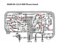
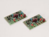
Hi! I have traced the Naim NA322/4 MM phono board PCB layout from some photos that I found online. I didn’t find any schematic, but there were enough pictures and some descriptions so that I could identify the parts.
Anyway I have some questions left:
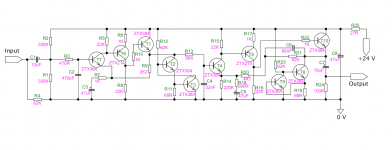
1. Can anybody tell me if I have identified the transistors correctly? I am not absolutely sure which of the 10 transistors are ZTX384 and which are ZTX214.
It was hard to tell this from the pictures. Unfortunately I don’t understand the circuit enough and don’t have enough background knowledge to really be able to figure this out logically.
2. Is the polarity of the tantalum caps correct?
3. I can use BC560 instead of ZTX214 and BC550 instead of ZTX384, right?
4. Do the transistors have to be matched? And which have to be matched?
Thanks so much in advance!
Anyway I have some questions left:
1. Can anybody tell me if I have identified the transistors correctly? I am not absolutely sure which of the 10 transistors are ZTX384 and which are ZTX214.
It was hard to tell this from the pictures. Unfortunately I don’t understand the circuit enough and don’t have enough background knowledge to really be able to figure this out logically.
2. Is the polarity of the tantalum caps correct?
3. I can use BC560 instead of ZTX214 and BC550 instead of ZTX384, right?
4. Do the transistors have to be matched? And which have to be matched?
Thanks so much in advance!
Attachments
Last edited:
")

JimSalabim - Respect ! I'm going to do this scheme .
Nice! One important thing to notice is that the transistor orientation in my layout is for ZTX834 and ZTX214. The pinout of the BC550C and BC560C is reversed. Just put them in the other way around!


An externally hosted image should be here but it was not working when we last tested it.
An externally hosted image should be here but it was not working when we last tested it.
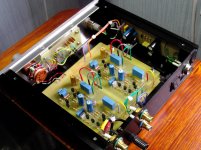
.....Very good sound !And yes I do know how close it is and why i is slightly different -with added power rail decoupling and more modern component selections, this is actually superior to the Naim circuit.Jim, This clone does not know how close it is to the original.
View attachment 723408
Your execution looks great - I assume it sounds as good as it looks
Last edited:
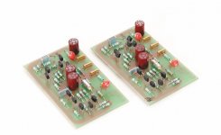
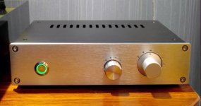
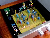
Hello everybody! Almost a year has passed . I changed the design of the preamp . I made a motherboard with star grounding . Made the input capacity switch ( 100, 150, 200, 250 pf ). Made the input resistance switch ( 22k, 33k, 47k , 62k, 75k, 100k). Installed gold-plated pins on the preamp Board . Now the Board is easily removed-if necessary . I still like the sound of that .


Last edited:
Jim, This clone does not know how close it is to the original.
View attachment 723408
That's from Neil James and it can be trusted.
Hello vsmusic,
your amp looks great and the possibility to adjust input capacity and input resistance make it very flexible. Short question regarding the input capacity.
@all,
is it sufficient enough to just replace the 470pF polystyrene cap? There are any side effectsto be expected by replacing this cap with f.e. 100pF cap?
Hello! I changed the 470 pf capacity on the board to a 100 pf rating . Additional capacity ratings are connected via a switch on the front panel . No negative consequences were identified .Signal paths to the capacitance and resistance setting switches pass through the motherboard .
Last edited:
- Status
- This old topic is closed. If you want to reopen this topic, contact a moderator using the "Report Post" button.
- Home
- Source & Line
- Analogue Source
- Naim NA322 MM phono board