While investigating mods for one of the preamps mentioned in my
onboard bass preamp thread, I googled "gyrator calculator" and all the ones I found give you the centre frequency and Q for given component values, which is fine if you want to analyze an existing circuit, but the opposite of what you need if you want to modify one or design your own, so I put together a little LTSpice simulation that calculates the components for you and lets you visualize how much you will deviate from the ideal response when you use standard values.
Background: one of the most commonly used circuit topologies for implementing a graphic EQ is shown e.g. in the
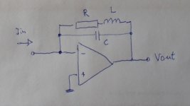
1980 National Semiconductor Audio & Radio Handbook (free download from TI), see "2.17 Octave Equalizers" on page 2-59 (page 68 of the PDF). Each pot wiper is grounded via an LCR series resonant circuit where, instead of using an expensive and bulky inductor, the inductance is "synthesized" with an active element (opamp or transistor), a capacitor and a couple of resistors, i.e. a gyrator. The reference above explains its operation in detail and provides the formulas to calculate the components for a given maximum boost/cut gain, centre frequency and Q value.
It also mentions that linear pots have very little effect around the centre position and a lot of effect very close to the extremes, so
S-taper pots (aka W-taper) are recommended. I'll address this in a later post, showing how a reasonable response can be achieved with linear pots (plus some caveats).
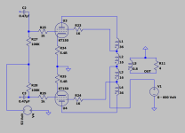
The simulation has two similar circuits, one with the calculated components and one where you enter manually the closest standard values, that way you can plot both and see how well they match:
I've parametrized the pot position to show the maximum, centre and minimum positions as well as half-way between centre and extremes. I've assumed 20k W-taper pots, which happen to be the type used for the tone control of the often cloned Tubescreamer pedal, so they aren't as hard to find as other values. A couple of good sources I've used in the past and have had no complaints about are
Tayda and
Musikding. Based on the curve shown in
Alpha's datasheet, those half-way positions would correspond roughly to 1k and 19k for a 20k pot, as shown.
So, to use the calculator, you simply edit the parameters at the top left, run the simulation, then enter the closest standard values to the calculated ones in the circuit on the right, run the simulation again, plot "calc" and "actual" to compare them, tweak as/if required. Some notes:
- The formulas have some approximations and the response you see for a single filter will change significantly as you add new ones. In particular, the max/min gain will decrease, so aim for a few dBs more than you need. In the 10-band example of the NS handbook they calculate for ~17 dB to get an actual maximum boost/cut of ~12 dB.
- R1 should be large, at least 68k or so to keep the approximations in the formulas acceptable.
- R3 will be the worst case load presented to the input buffer and eq opamps (the latter in parallel with the input impedance of the circuit you connect the EQ to). They use 3k, there are many decent opamps that will happily drive ~2k without too much THD. YMMV.
- To get the value of C2 closer to a standard one, you can tweak Q, which is generally not critical. Increase Q to decrease C2 and vice versa. This will also affect C1, but once you have C2 where you want it, you can tweak R1, which will affect C1 but not C2. Increase R1 to decrease C1 and vice versa.
The sim file is attached. As always, comments welcome!
Edit 7-Nov-2024: Sim file for version V2 (see
post #10) attached.

![firefox_euLlyKrVbT [22.12.24-21-24].jpg](https://www.diyaudio.com/community/attachments/firefox_eullykrvbt-22-12-24-21-24-jpg.1397231/ "firefox_euLlyKrVbT [22.12.24-21-24].jpg")


![DSCN0471[1].JPG](/community/data/attachments/1240/1240775-e76bcf584d259665f52169044d6dd62f.jpg?hash=52vPWE0llm)
![DSCN0469[1].JPG](/community/data/attachments/1240/1240776-aa5e1482064e731d56914251ed8df8c1.jpg?hash=ql4UggZOcx)
![DSCN0470[1].JPG](/community/data/attachments/1240/1240777-fc7d850b21df5ab5255d34e31069448f.jpg?hash=_H2FCyHfWr)
![DSCN0472[1].JPG](/community/data/attachments/1240/1240778-03eea967b2281dd8c18f3d38ae828b8a.jpg?hash=A-6pZ7IoHd)
![DSCN0473[1].JPG](/community/data/attachments/1240/1240779-2c849c9e8a0cdf3ea50d35f9edd05596.jpg?hash=LIScnooM3z)