Hello everyone!
I have a DHT (841) with filament bias , 0V on the grid. (3.5ma/300V anode)
If I want some A2 action using a mosfet source follower (DN2540N5-G), can I directly couple (no capacitor) the gate of the mosfet to my input (0V) , and still have the source at 0 volts?
Thanks🤙
I have a DHT (841) with filament bias , 0V on the grid. (3.5ma/300V anode)
If I want some A2 action using a mosfet source follower (DN2540N5-G), can I directly couple (no capacitor) the gate of the mosfet to my input (0V) , and still have the source at 0 volts?
Thanks🤙
If you want a DN2540 to run with 0V DC at the source, the gate must be biased to a small negative voltage.
In practice, it would be better to allow the gate to sit at 0V DC, and have a small DC positive voltage at the source. Then, you can increase the filament bias resistor to get the anode current back to where you want it.
The DN 2540 should run about 10mA of idle current. Preferably with a current source load, but a resistor is of course much easier to build.
Since the source is at 0V, you'll need positive and negative supply voltages to run the follower.
The positive side supply should have a standard (lossy) electrolytic cap, (47-100uF) to maintain a low impedance, but damped, drain node
Protect the DN 2540 with a G-S zener (diode K to source)
The heatsink should be bigger and heavier than is immediately apparent. The DN should idle at 40 ⁰C or lower.
Also it's easier to use low Crss MOSFETs of the standard (enhancement mode); these are readily available with 600V ratings and insulated (fullpak) packages
Do you know this article from Steve (Stephanie) Bench?
BTW transmitting tubes (like 841) in A2 mode are grid current hungry beasts.
841 eats even 3W driving power on the grid!
BTW transmitting tubes (like 841) in A2 mode are grid current hungry beasts.
841 eats even 3W driving power on the grid!
Hey Euro and Rod ) , thanks guys.
Thanks. Due to the rest of the amp, the 841 anode cant be over 300V.
Filament bias puts Vk = 3V
I have enchanment mode mosfets STP3NK60ZFP etc..was hoping to somehow do this DC...
Thanks. Due to the rest of the amp, the 841 anode cant be over 300V.
Filament bias puts Vk = 3V
I have enchanment mode mosfets STP3NK60ZFP etc..was hoping to somehow do this DC...
With these parameters this is a preamplifier .... rather the VAS stage (at about 25-28dB gain).
Why do you use it in A2?
The bias -about- is the filament bias resistor voltage + half of filament voltage, so about -6.75V.
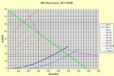
If you see the plate curves (in the previously linked article), this operating point is in the mostly curved part.
I used 841 (as VAS stage) with more current (and more Ua).
At these parameters the datasheet suggested -at least 220k anode load.
If you implement it's as resistive load, the estimated B+ at about 1kV!
Instead of it I use (cascode) CCS load, so B+ about Ua + half of required anode swing + 30..50V headroom for CCS.
At 2V RMS input it's capable even 130Vpp output, below 1% THD.
Hey Euro, I thought of A2 because I need 375V pk-pk swing. Anode can't be over 300V . I have 10M90 CCS (A 500V) . The load/following stage is a mosfet gate (direct coupled) - that's why my anode of the 841 can't be over 300V.
Thanks for the info on the (filament) bias voltage and the link to the positive grid curves.
+7.5 grid and 300V /24ma is looking pretty good
Thanks for the info on the (filament) bias voltage and the link to the positive grid curves.
+7.5 grid and 300V /24ma is looking pretty good
Last edited:
375Vpp means that the anode voltage swings (over the fixed 300V) +/- 188V (112V ... 488V).
See the plate curves.

This range (if you use CCS load) would be at 22mA anode current:
horizontal line from 100V/22mA/+15V to 500V/22mA/0V.
This suggest 300V/22mA/+7.5V static operating point.
The input must be at least 7.5V peek, 5.3V RMS.
So filament bias abandoned, the tube always use in A2.
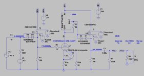
Something similar, than in this sample.

The first FET stage does not require such strong FET, any low power also usable.
BTW, these criteriums (300V anode, 500V B+) are the limiting factors, at large swing no other headroom in this system.
See the plate curves.

This range (if you use CCS load) would be at 22mA anode current:
horizontal line from 100V/22mA/+15V to 500V/22mA/0V.
This suggest 300V/22mA/+7.5V static operating point.
The input must be at least 7.5V peek, 5.3V RMS.
So filament bias abandoned, the tube always use in A2.
Something similar, than in this sample.

The first FET stage does not require such strong FET, any low power also usable.
BTW, these criteriums (300V anode, 500V B+) are the limiting factors, at large swing no other headroom in this system.
Many thanks Euro. I now have the 841 running deep in A2, 250V anode, 24ma, Vg +10V , like your above schematic (with a cap
+ mosfet (STP3NK60ZFP @ 220V drain, 22ma, 10K source resistor)
Unfortunately, A2 introduces unacceptable degeneration to the Audio signal (due to the cap/mosfet) compared to signal directly into the grid of the 841 ( filament bias, 300V anode CCS @3.5ma , even tho area of operation is "more linear"
Ill go back to my A1 , but keep the A2 option on the table , just in case.
One other thing I learned, the STP3NK60ZFP is really nice, and I will swap out other mosfets (wolfspeed Sic) in my amp out with the STP3NK60ZFP over Christmas
Cheers
- Home
- Amplifiers
- Tubes / Valves
- Source Follower with Filament Bias