Hello everyone!
I've recently finished my vintage inspired 2-way design and figured I'd share the journey here for any fellow members who may be interested in the concept or even building it for their self.
Soooo. Let's see it! What is it? Kronos is a sealed 2-way design utilizing the SEAS A26RE4 10inch Woofer and the Visaton FRS 5x-8 2inch in a WG.
Wait, isn't that Visaton driver a full range? Isn't this more of a "WAW" design? Yes, the Visaton is in fact a full range driver but it's actually being utilized as a tweeter in this design. It's mounted in the Visaton WG and integrates perfectly here with the SEAS woofer.
Isn't there already a similar design for this woofer? The A26? Yes, there is. However the tweeter for that design is rather pricey at $350+ each, while the cost here is $14 for each driver and around $19 for each WG currently on Parts Express. (Other options available as well, see below)
Okay okay, enough with the Q&A, let's get into how this came about and details of the design.
Introduction:
The
Kronos speaker build was born from a sense of nostalgia—rooted in childhood memories of sitting in front of my dad’s hi-fi system, mesmerized by the towering loudspeakers that filled the room with sound. Those classic designs, with their large woofers and cone tweeters, left a lasting impression. They had a presence—both visually and sonically—that felt larger than life. With Kronos, I set out to pay homage to that era and those experiences, blending the soul of vintage loudspeakers with the clarity and control of modern design. It’s a tribute to the sound that sparked a lifelong passion.
Driver Selection:
To bring the
Kronos concept to life, I carefully selected a driver lineup that reflects both the spirit of vintage design and the performance of modern components. For the low end, I chose the
SEAS A26RE4, a 10" paper-cone woofer known for its rich tone, effortless bass, and smooth upper response. It’s a direct nod to the classic wideband woofers of the past—capable of anchoring the system with warmth and authority.
For the top end, I went with a more unconventional approach: the
Visaton FRS5X, a small full-range cone driver, paired with the
Visaton WG 148 R round waveguide. This combination offers a controlled dispersion and a pleasantly natural tone that echoes the voicing of vintage paper cone tweeters, but with improved focus and clarity. To mount the FRS5X, I simply centered it on the waveguide and drilled my own holes—an easy but effective way to create a tweeter solution that stays true to the DIY spirit and captures the character of old-school designs.
Worth noting: With the rise of 3D printing and modern fabrication techniques, custom waveguides for drivers like the Visaton FRS5X are now readily available. For those looking for a more refined or drop-in solution,
Heissmann Acoustics offers a purpose-built 3D-printed waveguide specifically designed for the FRS5X. It's a great option for builders who want to simplify the mounting process while maintaining the same compact format and controlled directivity.
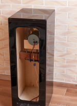
Enclosure Details:
The
SEAS A26RE4 woofer is housed in an
approximately 85-liter (about 3.0 ft³) sealed enclosure, giving it ample volume to breathe and deliver deep, full-bodied bass with natural roll-off—true to the character of classic hi-fi systems. This generous internal volume helps the woofer operate efficiently without excessive low-end boom, maintaining a balanced and effortless presentation.
The
Visaton FRS5X is isolated in its own
1-liter (0.035 ft³) sealed chamber. This small compartment ensures that the mid/tweeter remains unaffected by pressure changes from the woofer, allowing it to perform cleanly and consistently.
Throughout the cabinet,
adequate internal bracing was incorporated to minimize panel resonance and structural flexing. The result is a rigid and acoustically inert enclosure that supports clean, undistorted output even at higher playback levels.
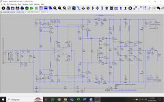
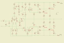
Crossover Details:
The
Kronos crossover began as a theoretical layout, designed with target values based on driver behavior and desired voicing. From there, it was refined
entirely by ear, with countless hours of listening and adjustment until the final values locked into place. This process allowed the system to reach a balance that felt natural, dynamic, and emotionally engaging—true to the character I set out to achieve.
The
SEAS A26RE4 woofer, a modern version of the W26 used in classic designs like the
Dynaco A25, has a naturally smooth roll-off that doesn’t strictly require filtering. That said, I chose to add a small
0.33 mH series inductor to gently tame the upper midrange, making the speaker more forgiving and enjoyable at higher volumes—reducing the risk of harshness or “shouting” without robbing it of presence.
For the
FRS5X tweeter, mounted in a waveguide,
no series resistor was needed. The waveguide not only improves sensitivity and dispersion control but also helps the FRS5X blend naturally with the woofer. Without the waveguide, I would have added around
1 ohm of series resistance to balance its output. The high-pass network is
essentially first-order, using a capacitor for the main roll-off. A
parallel inductor was added to keep the tweeter’s upper resonance from bleeding through—simple, but effective.
While a textbook solution might call for an
RCL (resistor-capacitor-inductor) network for perfect impedance correction, I found that in practice,
a single coil did the job just fine. An optional overall impedance compensation network was included for the sake of completeness, but it's more a nice-to-have than a necessity in this build.
In the end, the crossover reflects the spirit of the whole project—
minimalist, purposeful, and guided by listening above all else.
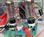
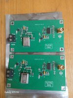
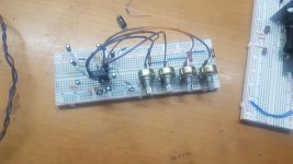
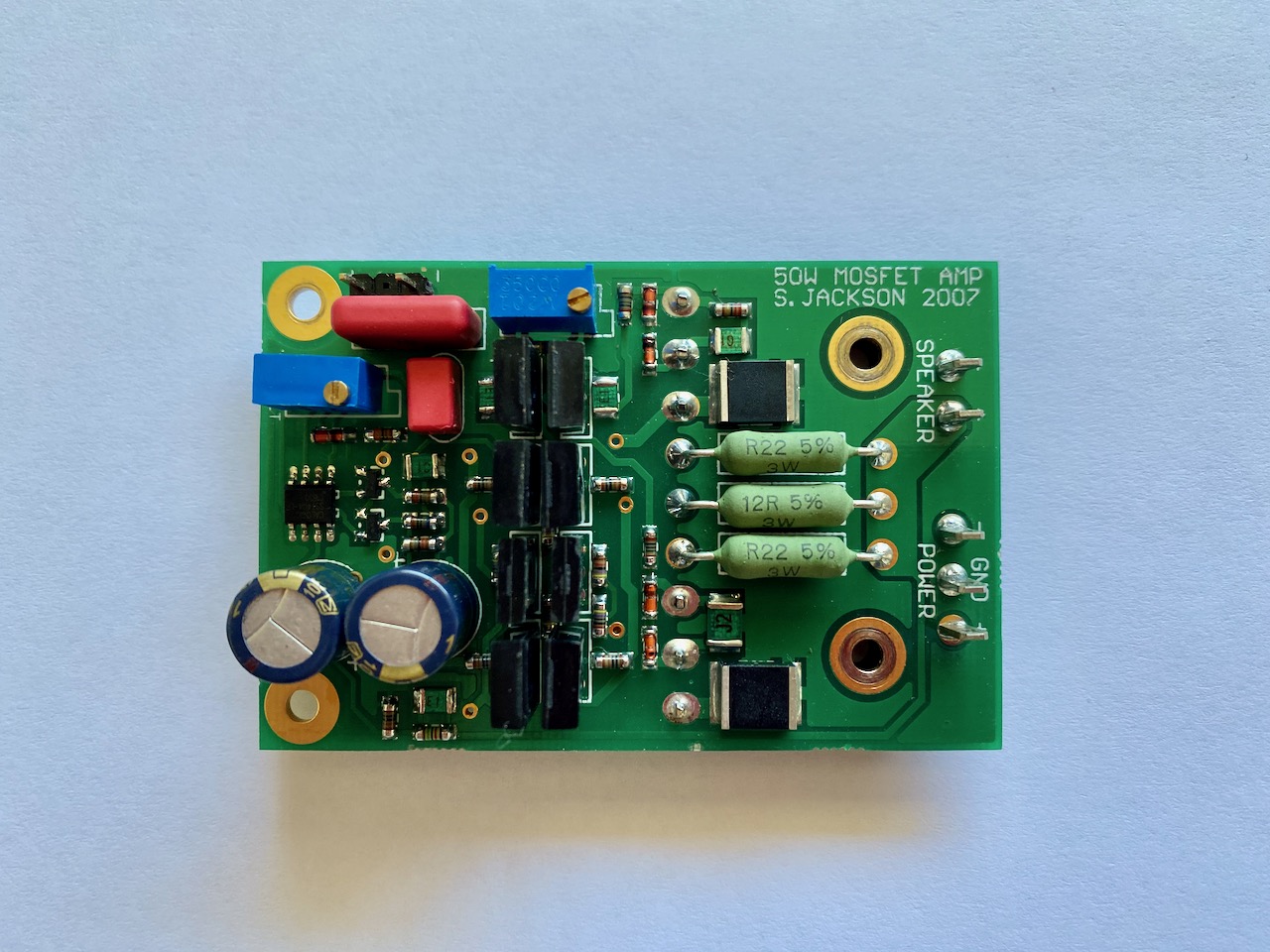
CROSSOVER PCB:
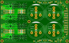
To make this project more accessible for others—especially those new to DIY loudspeakers—I went a step further and
designed a dedicated PCB for the crossover network. Rather than relying on point-to-point wiring or a perfboard layout, this custom PCB ensures clean, repeatable assembly and proper part spacing, helping reduce the chance of wiring errors and making the build experience more enjoyable.
The board is laid out with component footprints matched to the actual values used in the final design, and it includes clear labeling for easy reference. Whether you're a first-time builder or a seasoned DIYer, this PCB simplifies the process and makes it easier to achieve consistent results.
I’ll be including a
download link at the end of this presentation with everything needed to build your own pair of Kronos speakers—including crossover schematics, PCB files, enclosure plans, and additional notes gathered throughout the build.
Finished Speaker:
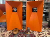
Here’s a look at the
finished Kronos speaker. Aesthetically, I realize this look might not be for everyone—but that was never the goal. I wanted the finish to reflect the spirit of the project:
cheap, fun, and bold. The result is something unique, eye-catching, and artistic.
I’ve had a few people ask how I achieved the finish, so here’s a quick breakdown:
- I started with a roll-on bedliner called "Total Coat" to create a tough, textured surface.
- After that, I applied a Rust-Oleum yellow paint as the main color.
- For added visual interest, I used Rust-Oleum Black Marbling spray, which creates a random web-like texture and gives the surface a more dynamic, artistic feel.
- Finally, I sealed everything with a Rust-Oleum matte clear coat, which helps protect the finish and reduce glare.
It’s not a high-end veneer or mirror-gloss lacquer—but for a fun, rugged speaker with personality, it gets the job done.
Cheap, effective, and satisfying to see come together.
Final Measurements:
Below you can see the
final measured response of the Kronos design. The results highlight just how well the
Visaton FRS5X in a waveguide and the
SEAS A26RE4 woofer integrate—especially considering the simplicity of the crossover network.
The response is impressively smooth, with excellent tonal balance and a natural transition between drivers. The waveguide not only improves the FRS5X’s efficiency and dispersion but also allows it to blend seamlessly with the larger woofer, avoiding the typical disconnect you might expect from such different-sized drivers. The minimal crossover does just enough to shape the response where needed, while preserving the raw, engaging character of the drivers.
This measurement validates the listening impressions—
a coherent, dynamic speaker that stays true to its vintage inspiration while performing with modern finesse.
Listening Impressions:
The final implementation of the
Kronos exceeded my expectations. While I didn’t build these to be the ultimate reference monitor or the “end-all-be-all” speaker, the result is something that sounds
exceptionally good—better than I had originally imagined.
The
bass performance is particularly impressive, with deep, full extension that's further enhanced by
room gain and proper placement. The SEAS woofer really shines here, delivering weight and authority without muddiness.
Tonally, the speaker holds up well across a wide variety of genres. So far, I've enjoyed everything from
Rock, Jazz, Pop, Hip-Hop, EDM, to
Classical, and the system has handled them all with confidence. The highs are clean without being harsh, mids are clear and natural, and the overall balance feels cohesive and engaging.
Even at
very high listening levels, the speaker
maintains its composure, with no sense of strain or collapse—perfect for those nights when you just want to crank things up and let loose.
I’ve also had a few friends over to hear them, and the
reactions have been consistently surprised and impressed. There’s something satisfying about watching someone sit down with no expectations, and then light up the moment the music starts.
In Conclusion:
The
Kronos has accomplished everything it was designed to do—and then some. It’s a speaker that brings together nostalgic inspiration, modern performance, and hands-on DIY fun in one cohesive package. I’m genuinely proud of how it turned out, and I know I’ll be enjoying these speakers for
many years to come.
For those interested in diving deeper into the design—or even building a pair yourself—I’ve put together a
comprehensive resource link below. This presentation has only scratched the surface, and the download includes detailed plans, crossover files, PCB layout, measurements, and more.
If you have any
questions or run into issues, don’t hesitate to reach out. I’m always happy to help fellow builders in any way I can.
Thanks for taking the time to check out my project—I hope it inspires you to build something of your own.
LINK TO KRONOS BUILD PLANS: https://drive.google.com/drive/folders/1Kpa-w3JEGQmEdG6RKKRCQnM0pMenjgjl?usp=sharing


 ), while there are two preceding threads where you can refresh memory.
