


GB F5 Guide (pcb version 2)
As promised, I would make a guide to the boards and in particular to the additions I have made to the F5. I decided to do this in the blog, because then you can give me comments which I can use for improving the doc. However I'm not done at all, but I thought it would be nice to give you access to the BOM I have made.
IMPORTANT: Before you start stuffing your boards, you must read the manual/article written by Nelson Pass available for download on the First Watt website (First Watt: Products: F5).
Detailed guide by Steve and Matt: https://www.diyaudio.com/forums/pass-...mentation.html
PCB
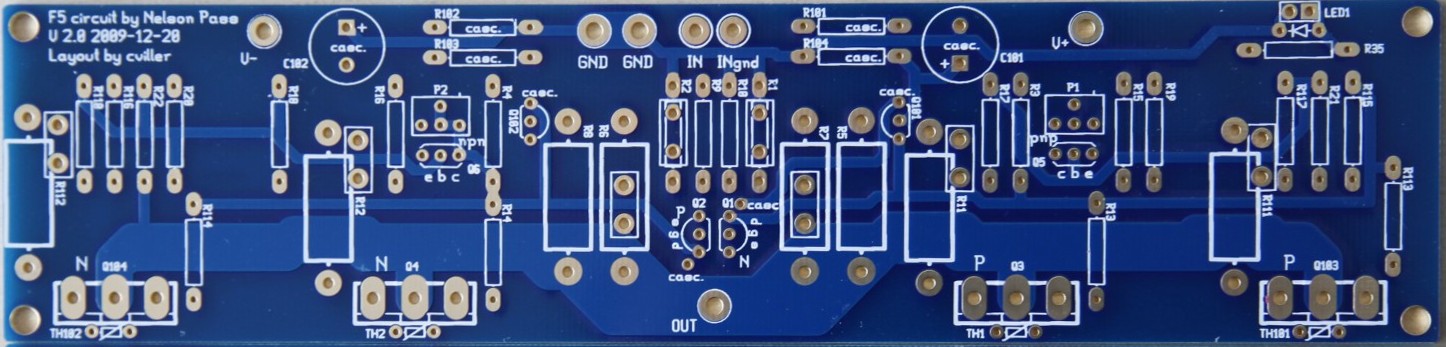
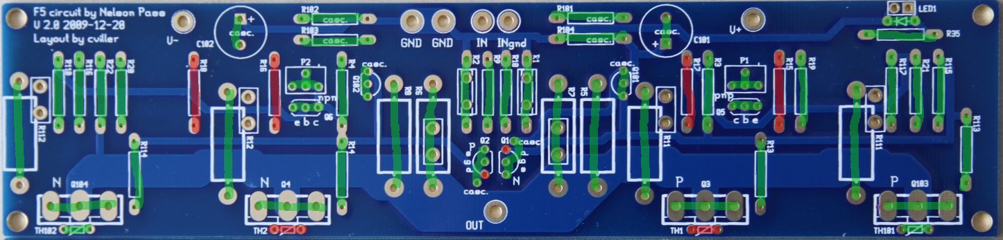
Here is a picture of the pcb.
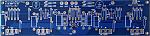
There are no more boards available, but you can order F5 boards on the diyAudio store.
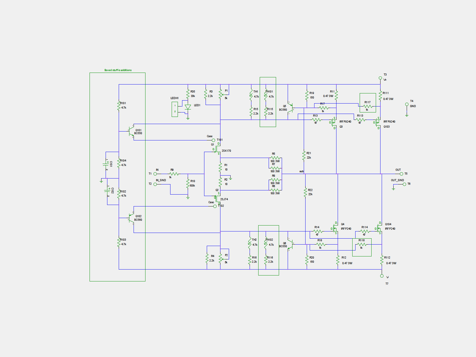
Schematics

Optionality
With the addition of optional extra output mosfets and cascoding, there are many possible ways to build the amp. Here I'll try to explain some of them.
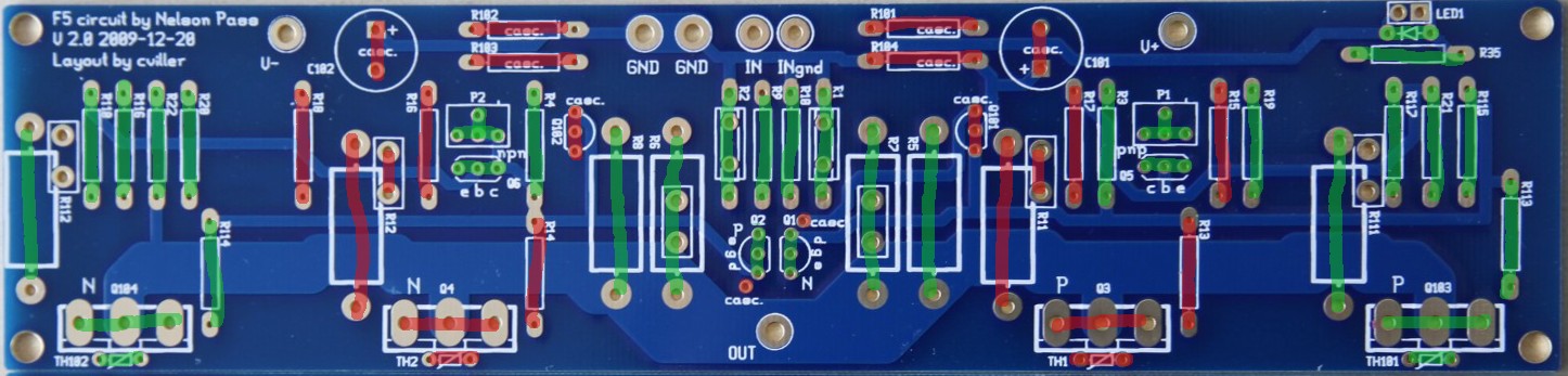
Stock F5 example
Greens are populated and reds are left open.
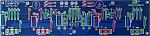
Here I have used the outputs farthest apart and notice I have also used the corresponding thermistor and sensing resistors.
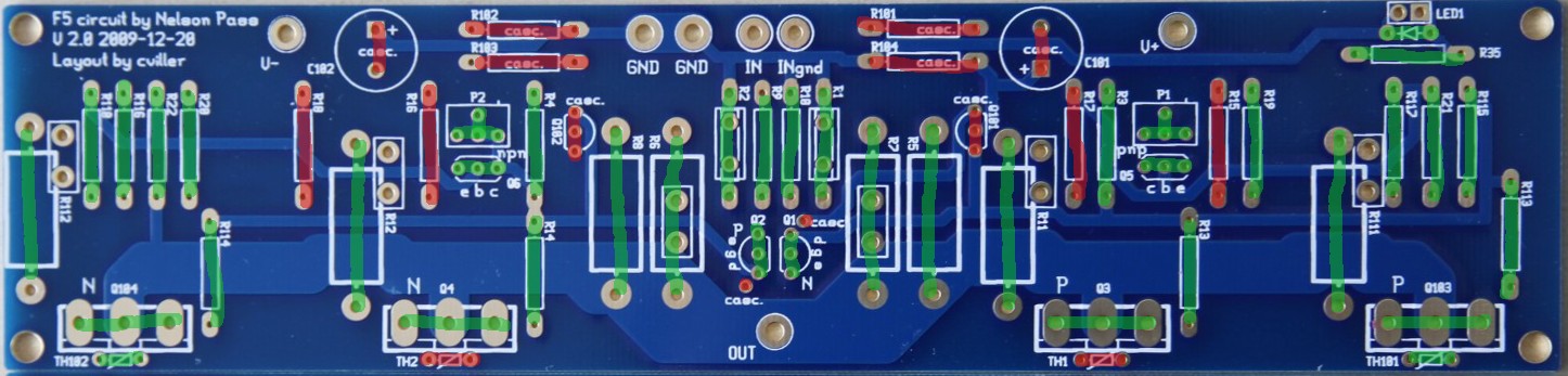
Double Ouput Mosfets
Greens are populated and reds are left open.
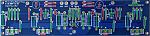
When the other output device is populated, you should not add extra thermistors, but you can chose if you want to use the inner our outer mosfet as reference - I have chosen the outer.
The output fets must be matched in pairs - the two N's should have same vgs and the P's must have same vgs.
The extra output devices will allow you to run the amp at higher currents, which is good for driving low impedance speakers. But be sure to have a large enough heatsink if you chose to crank up the bias.
Cascode and Double Output
Greens are populated and reds are left open.
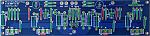
The cascoded option with double outputs requires two extra transistors and the voltage dividers. Notice that one of the legs of both jfets has to be bend slightly to connect to the hole designated "casc.".
The cascoded option is mainly there to allow for slightly higher supply voltages. Doing the cascode does require some electronics skills, because you may need to adjust some values to get the required headroom for operations. You can read more about cascodes in Nelson Pass' excellent article on the topic: https://www.passdiy.com/pdf/articles/cascode.pdf
BOM
bom.pdf
Output devices
You can use many different output devices for this amp, but the standard is Fairchilds FQA19N20C and FQA12P20C. They can be difficult to get your hands on, so you can use the IRFP parts instead.
Sourcing components
You can order component kits from various diyAudio members.
North America
jackinnj: Tech DIY Company Store (many full clone kits)
Europe
h_a: F5 amp transistor kits
FAQ
Increasing the feedback resistor will lower the amount of feedback, so you'll get more gain and distortion.
I use 14-16 gauge wire for the PSU and outputs and shielded wires for the input. I don't think this is the place where you will see the most improvement from exotic parts, but don't use crummy wire either.
You can use double outputs to lower the load on each mosfet or increase the total bias. If you increase the bias to twice the stock value, then your heatsink needs to dissipate twice as much heat.
With the stock F5, you are dissipating around 60 watt per channel, so you need a 0.3C/W sink to stay below 20C over ambient temperature.
With the double amount of dissipation, your sinks need to be 0.15C/W per channel.
IMPORTANT: Before you start stuffing your boards, you must read the manual/article written by Nelson Pass available for download on the First Watt website (First Watt: Products: F5).
Detailed guide by Steve and Matt: https://www.diyaudio.com/forums/pass-...mentation.html
PCB
Here is a picture of the pcb.
There are no more boards available, but you can order F5 boards on the diyAudio store.
Schematics
Optionality
With the addition of optional extra output mosfets and cascoding, there are many possible ways to build the amp. Here I'll try to explain some of them.
Stock F5 example
Greens are populated and reds are left open.
Here I have used the outputs farthest apart and notice I have also used the corresponding thermistor and sensing resistors.
Double Ouput Mosfets
Greens are populated and reds are left open.
When the other output device is populated, you should not add extra thermistors, but you can chose if you want to use the inner our outer mosfet as reference - I have chosen the outer.
The output fets must be matched in pairs - the two N's should have same vgs and the P's must have same vgs.
The extra output devices will allow you to run the amp at higher currents, which is good for driving low impedance speakers. But be sure to have a large enough heatsink if you chose to crank up the bias.
Cascode and Double Output
Greens are populated and reds are left open.
The cascoded option with double outputs requires two extra transistors and the voltage dividers. Notice that one of the legs of both jfets has to be bend slightly to connect to the hole designated "casc.".
The cascoded option is mainly there to allow for slightly higher supply voltages. Doing the cascode does require some electronics skills, because you may need to adjust some values to get the required headroom for operations. You can read more about cascodes in Nelson Pass' excellent article on the topic: https://www.passdiy.com/pdf/articles/cascode.pdf
BOM
bom.pdf
Output devices
You can use many different output devices for this amp, but the standard is Fairchilds FQA19N20C and FQA12P20C. They can be difficult to get your hands on, so you can use the IRFP parts instead.
Sourcing components
You can order component kits from various diyAudio members.
North America
jackinnj: Tech DIY Company Store (many full clone kits)
Europe
h_a: F5 amp transistor kits
FAQ
Quote:
What happen in F5 if I use 60 or 75 ohm in place of 50 one ?
Quote:
What cables do you use?
Quote:
Could you give more information about possible changes in bias and other settings for double mosfet option comparing to stock. What are your recommendations for the power supply/transformer and heat sinks?
With the stock F5, you are dissipating around 60 watt per channel, so you need a 0.3C/W sink to stay below 20C over ambient temperature.
With the double amount of dissipation, your sinks need to be 0.15C/W per channel.
Quote:
Thanks to AudioSan for this guidance to cascode calculation:
Rail voltage divided by (R103+R102) multiplied by R102 = coscoded voltage.
so f.ex: 35V rails / (4.75K+4.75K) x 4.75K= 17.5V to the J-fets. to get higher voltage for the J-fets, just increase R102 and/or decrease R103. and the other way around to lower the voltage.
the caps can be around 10uF. not very important
Total Comments 98
Comments
-

 Correct!
 Posted 18th November 2010 at 02:57 PM by cviller

-
Cviller, will you have more F5 boards any time soon?Posted 18th November 2010 at 05:43 PM by jdec
-
I'm so busy with work and studies, so I am not going to order again, but diyAudio has started to sell my layouts here: Home pagePosted 18th November 2010 at 06:38 PM by cviller
-
 I have a pair of the v2 pcb's and a couple of 24V trafos...
(33-34V-DC) and IRFP-mosfets...
Will I need to do much change to the last page BOM?
Arne KPosted 14th December 2010 at 11:11 PM by Cobra2
-
So I guess that silence is "OK" ?
Arne KPosted 17th December 2010 at 11:10 PM by Cobra2
-
Sorry for the silence - busy with work, server breakdown and now my wife is at the hospital.
I still have more psu boards, but no more F5's. I can't sell them before I get a order site up and running.
Arne K, I think it will work quite well, but I have not tried. You may need to do a few calculations to make sure that the jfets are not exposed to too high voltages, and depending on your preamp, you may also need to increase the gain to get full potential of the rails.
diyAudio store will be selling a longer version of the original F5 schematics, but not what I call v2 (double output and cascode). So if someone wants to do a small batch of the v2, which will probably never be sold by diyAudio, you can send me a pm and we might be able to figure out something.Posted 18th December 2010 at 06:36 AM by cviller
-
I recently bought 2 of your F5 PCBs version 1.00 here at the diyaudio shop. Suits the BOM your provide to the 1st version of your boards as well?
KaiPosted 2nd January 2011 at 02:55 AM by Mallard
-
Yes, the boards sold at diyAudio store are standard F5's, so basically any F5 bom will work.Posted 2nd January 2011 at 09:52 AM by cviller
-
 That might be quite interesting. Or I can just double the output parts by hardwiring them.Quote:Originally Posted by cviller
diyAudio store will be selling a longer version of the original F5 schematics, but not what I call v2 (double output and cascode). So if someone wants to do a small batch of the v2, which will probably never be sold by diyAudio, you can send me a pm and we might be able to figure out something.
I think I will go with an all-point-to-point, no boards at all!! Posted 4th January 2011 at 06:26 PM by regiregi22
-
CViller,
I would still like four or more F5 ver2 boardsPosted 19th January 2011 at 05:08 AM by Fcrawley
-
There is no simple answer to that request. I would prefer to get diyAudio to sell them, but they might have too much in the pipeline.Posted 19th January 2011 at 05:53 AM by cviller
-
Before organising a new batch of F5 v2 boards, I would like to hear if someone would share some listening and building impressions of using the cascoded and dual mosfet options?
I would like to know if there are things I should change before the next batch.Posted 19th January 2011 at 06:22 AM by cviller
-
Interested in a pair of V2 F5 boards
Hi,
I am looking to build a cascoded and paralleled F5. These V2 boards will be very helpful. Can I get a pair of these, whenever you are planning to make some more or have few left.
Thanks.Posted 27th January 2011 at 09:07 AM by anilva
-
I am currently trying to persuade diyaudio to sell them - they are much better at snappy delivery.
 Posted 27th January 2011 at 11:08 AM by cviller
-
Christian,
I still need the (4)F5 ver 2 boards. People are asking me if I will build amps for them. I would rather sell them the boards or send them to you. Ha!
FredPosted 5th February 2011 at 08:04 AM by Fcrawley
-
Hi Fred, I have updated the layout to diyAudio standard sizes, but I still need to clean up a few things, but this will happen tomorrow I hope - then it is just a few months of waiting before they pop up on diyAudio store...Posted 5th February 2011 at 08:10 AM by cviller
-
Christian,
Thanks for all you do and the help you provide others. We need a lot more people in this like you.
FredPosted 8th February 2011 at 12:26 AM by Fcrawley
-
I'm confused. In the stock F5, should Q101 be populated instead of or in addition to Q1?Quote:Originally Posted by nycavsr2000
Just a friendly nudge for you Christian, I know you are busy
 . Update that Stock F5 pic whenever you can. You still have Q101 incorrectly marked (or unmarked if you know what I mean)
  .
.
Thankfully, my speakers are 95dB/1w/1m efficient [8 ohm speaker] or 95dB/2.83V/1m sensitive so the stock F5 should do just fine .
.
,
Anand.Posted 19th March 2011 at 11:27 PM by strider75
-
Q101 and Q102 are marked "casc." because they are needed for cascoding. You need to use Q1 and Q2 no matter if you are building a stock F5 or a cascoded.Posted 20th March 2011 at 05:59 AM by cviller
Updated 20th March 2011 at 06:01 AM by cviller -
Thanks for the reply Christian. I'm having some issues with mine and I was backtracking to figure them out, saw Anand's comments and it caught my eye.Posted 20th March 2011 at 11:52 AM by strider75

