


GB F5 Guide (pcb version 2)
As promised, I would make a guide to the boards and in particular to the additions I have made to the F5. I decided to do this in the blog, because then you can give me comments which I can use for improving the doc. However I'm not done at all, but I thought it would be nice to give you access to the BOM I have made.
IMPORTANT: Before you start stuffing your boards, you must read the manual/article written by Nelson Pass available for download on the First Watt website (First Watt: Products: F5).
Detailed guide by Steve and Matt: https://www.diyaudio.com/forums/pass-...mentation.html
PCB
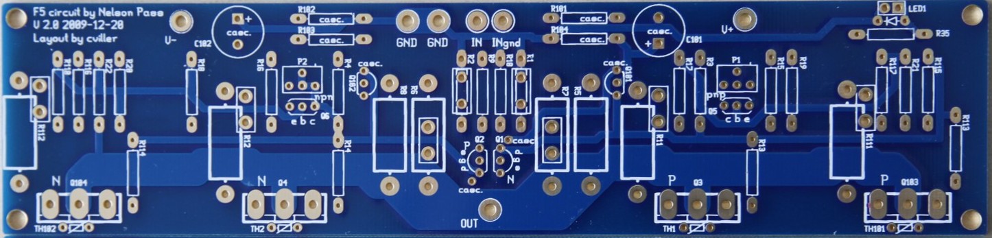
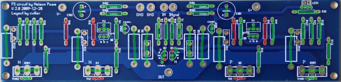
Here is a picture of the pcb.
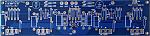
There are no more boards available, but you can order F5 boards on the diyAudio store.
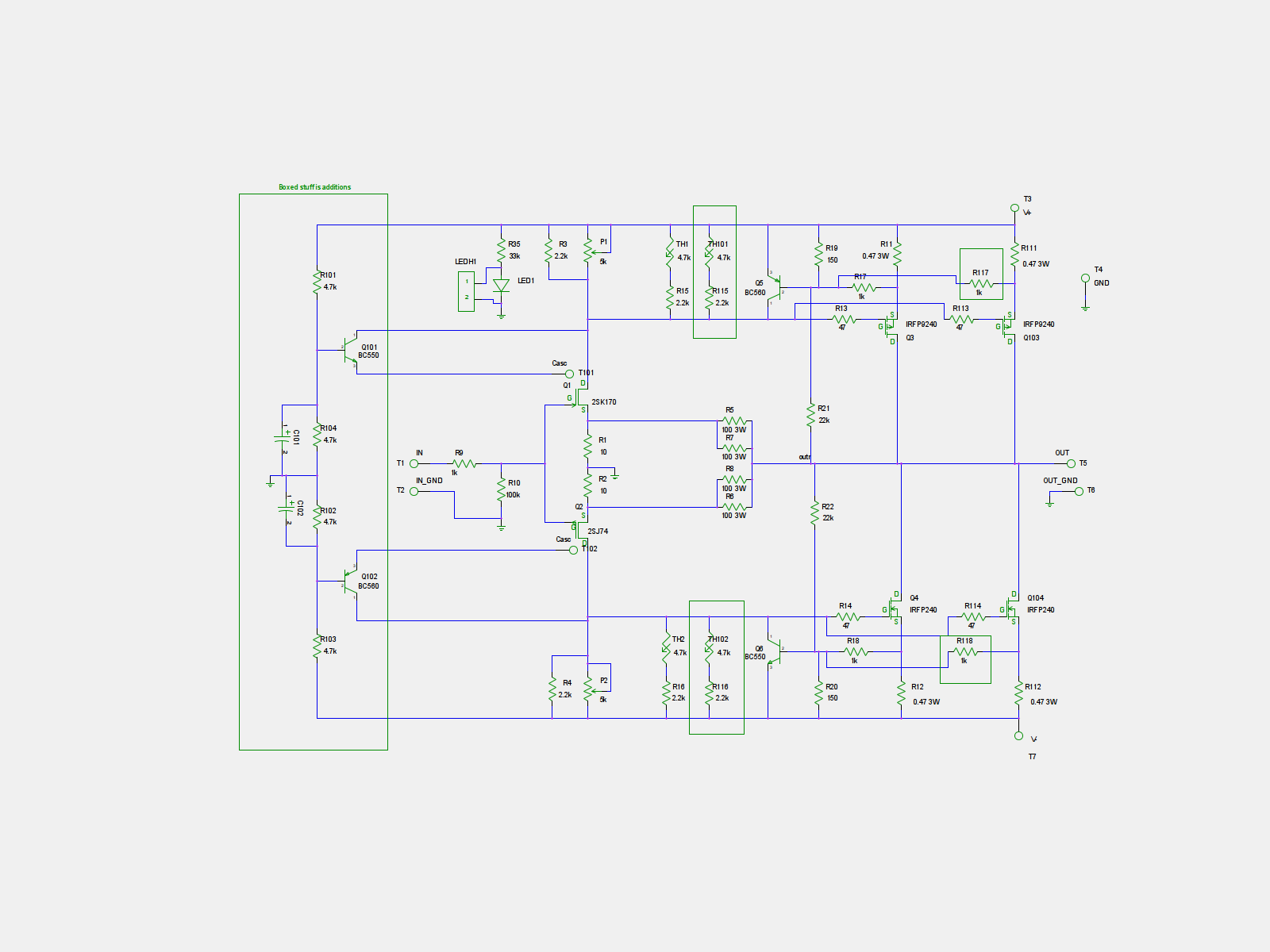
Schematics

Optionality
With the addition of optional extra output mosfets and cascoding, there are many possible ways to build the amp. Here I'll try to explain some of them.
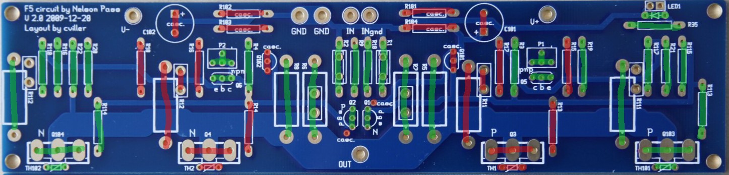
Stock F5 example
Greens are populated and reds are left open.
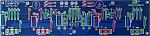
Here I have used the outputs farthest apart and notice I have also used the corresponding thermistor and sensing resistors.
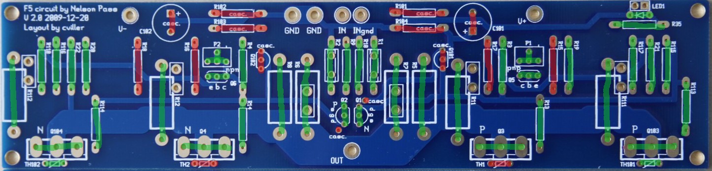
Double Ouput Mosfets
Greens are populated and reds are left open.
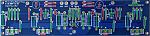
When the other output device is populated, you should not add extra thermistors, but you can chose if you want to use the inner our outer mosfet as reference - I have chosen the outer.
The output fets must be matched in pairs - the two N's should have same vgs and the P's must have same vgs.
The extra output devices will allow you to run the amp at higher currents, which is good for driving low impedance speakers. But be sure to have a large enough heatsink if you chose to crank up the bias.
Cascode and Double Output
Greens are populated and reds are left open.
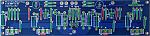
The cascoded option with double outputs requires two extra transistors and the voltage dividers. Notice that one of the legs of both jfets has to be bend slightly to connect to the hole designated "casc.".
The cascoded option is mainly there to allow for slightly higher supply voltages. Doing the cascode does require some electronics skills, because you may need to adjust some values to get the required headroom for operations. You can read more about cascodes in Nelson Pass' excellent article on the topic: https://www.passdiy.com/pdf/articles/cascode.pdf
BOM
bom.pdf
Output devices
You can use many different output devices for this amp, but the standard is Fairchilds FQA19N20C and FQA12P20C. They can be difficult to get your hands on, so you can use the IRFP parts instead.
Sourcing components
You can order component kits from various diyAudio members.
North America
jackinnj: Tech DIY Company Store (many full clone kits)
Europe
h_a: F5 amp transistor kits
FAQ
Increasing the feedback resistor will lower the amount of feedback, so you'll get more gain and distortion.
I use 14-16 gauge wire for the PSU and outputs and shielded wires for the input. I don't think this is the place where you will see the most improvement from exotic parts, but don't use crummy wire either.
You can use double outputs to lower the load on each mosfet or increase the total bias. If you increase the bias to twice the stock value, then your heatsink needs to dissipate twice as much heat.
With the stock F5, you are dissipating around 60 watt per channel, so you need a 0.3C/W sink to stay below 20C over ambient temperature.
With the double amount of dissipation, your sinks need to be 0.15C/W per channel.
IMPORTANT: Before you start stuffing your boards, you must read the manual/article written by Nelson Pass available for download on the First Watt website (First Watt: Products: F5).
Detailed guide by Steve and Matt: https://www.diyaudio.com/forums/pass-...mentation.html
PCB
Here is a picture of the pcb.
There are no more boards available, but you can order F5 boards on the diyAudio store.
Schematics
Optionality
With the addition of optional extra output mosfets and cascoding, there are many possible ways to build the amp. Here I'll try to explain some of them.
Stock F5 example
Greens are populated and reds are left open.
Here I have used the outputs farthest apart and notice I have also used the corresponding thermistor and sensing resistors.
Double Ouput Mosfets
Greens are populated and reds are left open.
When the other output device is populated, you should not add extra thermistors, but you can chose if you want to use the inner our outer mosfet as reference - I have chosen the outer.
The output fets must be matched in pairs - the two N's should have same vgs and the P's must have same vgs.
The extra output devices will allow you to run the amp at higher currents, which is good for driving low impedance speakers. But be sure to have a large enough heatsink if you chose to crank up the bias.
Cascode and Double Output
Greens are populated and reds are left open.
The cascoded option with double outputs requires two extra transistors and the voltage dividers. Notice that one of the legs of both jfets has to be bend slightly to connect to the hole designated "casc.".
The cascoded option is mainly there to allow for slightly higher supply voltages. Doing the cascode does require some electronics skills, because you may need to adjust some values to get the required headroom for operations. You can read more about cascodes in Nelson Pass' excellent article on the topic: https://www.passdiy.com/pdf/articles/cascode.pdf
BOM
bom.pdf
Output devices
You can use many different output devices for this amp, but the standard is Fairchilds FQA19N20C and FQA12P20C. They can be difficult to get your hands on, so you can use the IRFP parts instead.
Sourcing components
You can order component kits from various diyAudio members.
North America
jackinnj: Tech DIY Company Store (many full clone kits)
Europe
h_a: F5 amp transistor kits
FAQ
Quote:
What happen in F5 if I use 60 or 75 ohm in place of 50 one ?
Quote:
What cables do you use?
Quote:
Could you give more information about possible changes in bias and other settings for double mosfet option comparing to stock. What are your recommendations for the power supply/transformer and heat sinks?
With the stock F5, you are dissipating around 60 watt per channel, so you need a 0.3C/W sink to stay below 20C over ambient temperature.
With the double amount of dissipation, your sinks need to be 0.15C/W per channel.
Quote:
Thanks to AudioSan for this guidance to cascode calculation:
Rail voltage divided by (R103+R102) multiplied by R102 = coscoded voltage.
so f.ex: 35V rails / (4.75K+4.75K) x 4.75K= 17.5V to the J-fets. to get higher voltage for the J-fets, just increase R102 and/or decrease R103. and the other way around to lower the voltage.
the caps can be around 10uF. not very important
Total Comments 98
Comments
-
 Hi,
Hi,
What happen in F5 if I use 60 or 75 ohm in place of 50 one ?
I have a 2 x 100 ohm now and I try just one 100 ohm
and I don't like sound at all.
My F5 use BUZ900/905 at high 2A each current.Posted 14th March 2010 at 03:52 PM by Jozef

-
Just a friendly nudge for you Christian, I know you are busy
 . Update that Stock F5 pic whenever you can. You still have Q101 incorrectly marked (or unmarked if you know what I mean)
  .
.
Thankfully, my speakers are 95dB/1w/1m efficient [8 ohm speaker] or 95dB/2.83V/1m sensitive so the stock F5 should do just fine .
.
 ,
,
Anand.Posted 14th March 2010 at 04:18 PM by nycavsr2000
-
Altman F5?
Would there be any downside if the doublw o/p pair design was converted to the Altman SPLIF design? Any advantages for this amp?
... JhPosted 5th April 2010 at 01:19 PM by jameshillj
-
 Altman F5 - I have not studied the topology, so I can't say.
Barniboy, you are right, I have not made any cascoding of the output fets, so "full cascoded" is probably a misguided expression in this context.Posted 12th May 2010 at 10:52 PM by cviller
-
 Hey Christian. I'm thinking of setting up my F5 with double output MOSFETS, to better drive my low impedance speakers. Question is, what is the standard build power supply good for power wise? Would larger capacitors, or higher power resistors be required at twice the output power?
Thanks!Posted 14th October 2010 at 08:21 PM by Horio
-
The psu's are always conservatively rated in Nelson's amps, but if I were to run twice the current, I would consider building mono-blocks (could be in same chassis), but separate psu for each channel.Posted 15th October 2010 at 02:13 PM by cviller
-
What if I were to increase to double the capacitance of the C bank, and bump up the resistor W. Would the board be able to handle double the current?
Thanks Christian.Posted 18th October 2010 at 05:48 PM by Horio
-
The boards will handle the current, but if you are in doubt, you can take away the solder-screen around the three small vias and solder in some scrap component legs. The three vias is the weakest spot.Posted 18th October 2010 at 06:35 PM by cviller
-
How did you calculate R35 for the LED?Posted 25th October 2010 at 02:56 AM by labjr
-
I generally like my leds to be dimmed down a lot, so I was going for a few mA. The voltage drop is 20V and with a 20k resistor, you end up with 1mA. It is simple Ohms law, but generally I think you would be better of experimenting - lower value, brighter light. Just don't go too low on resistor value - I would personally not go under 10k for the leds I use.Posted 27th October 2010 at 09:28 AM by cviller
-
 Are there any more f5 boards available? your order page shows only f4Posted 31st October 2010 at 01:23 PM by buzzforb
-
No, but diyAudio has started to sell some:
DiyAudio PCB Bank
very similar to my first version of the F5, so it does not include all the extra stuff as the v2 in this blog does.Posted 31st October 2010 at 01:37 PM by cviller
-
Hello Cvillier,
I notice the board as been revised to a V2 version, How does it differ from the boards i got from you in march?
Also what is the highest PSU voltage if running your full board cascode /outputs etc ...i would like to run 20v @ 800 va tranny ...
regards,
A.waynePosted 3rd November 2010 at 07:43 PM by a.wayne
-
Hi A.wayne,
My version 2 of the F5 is the one with cascoding and extra outputs - I guess that is the one you have. It will probably not be offered on diyAudio store, if that was what you were asking.
Regarding the PSU voltage, it depends on how you do the cascoding, but a 20v tranny should not be a problem. Cascoding the F5 does require a bit of tinkering and calcuations - perfect diy project, but much more advanced than putting together a kit.Posted 3rd November 2010 at 07:53 PM by cviller
-
Hello Cvillier,
Thanks for the response, last bit for now
Could you be a bit more specific on the tinkering required, what on the board would need to be tinkered with? I would like to attempt the full board.
Has anyone built the full board as yet ?
Also if i do the full outputs but without cascode, would i need to lower the voltage , Yes?
regards,
A. WaynePosted 3rd November 2010 at 08:13 PM by a.wayne
-
Hello Cviliier ,
Looking it over again , I have decided to do the full board with the 20v trannies (400 VA/channel)
regards,Posted 7th November 2010 at 09:44 PM by a.wayne
-
Proposed V3.0 of the F5 board
Cviller:
I have a suggestion for a 3.0 version of your F5 board. Allow splitting the board between upper (P-channel) and lower (N-channel) parts of the circuit. This allows the following:
1. Using the 2 halves in a circlotron fashion or a balanced F5 (X) topology. The 2 halves of the board can be used with either N-channel or P-channel parts.
2. Optionally breaking the board along a scribe line between the two halves to provide additional options for mounting the output FETs to heatsinks. To make this work best requires attention to details such as using a star topology on the speaker outputs so that the feedback is not compromised by wire lengths between the boards and the amplifier output connectors.
If you are interested in persuing this further, I will send you more details, otherwise I will likely develop my own F5 layout for this.Posted 12th November 2010 at 01:33 AM by lhquam
-
I'm almost done with my F5 Boards. I have a couple of questions.
1. The bias and offset pots. I assume they install with the adjustment screw on the left as you read the writing on the board. I want to be sure the bias adjusts up as I turn clockwise.
2. I am using the Zetex 450-550 parts. I'm a little confused since Zetex doesn't print the part number on the long flat side of the part but on the short flat side. It is an e-line package which make it appear backwards when compared to a TO-92 package.
ThanksPosted 18th November 2010 at 02:25 AM by labjr
-
1. I never answer this question directly, because there might be differences between pot brands. You need to measure the resistance across R3 and R4 and see which way turns the resistance down.
2. Yes, it is confusing with the labeling on e-line packages. If you look at my old guide ( https://viller.eu/audio/2009jan_gbf5/gbf5_guide.pdf ), on page 5 there is a picture of the zetex pin-out. I think that will solve your problem.Posted 18th November 2010 at 05:54 AM by cviller
-
So we want the resistance across R3, R4 at zero to start?
I think I get it now. The Zetex parts have the same CBE pin configuration. Just the package is a different shape. I was confused thinking they were going to be a TO-92 package with reversed pin configuration which is not the case.
ThanksPosted 18th November 2010 at 02:53 PM by labjr

