Of course, to avoid further confusion, these points up here are connected. I just made them separate to put some details in evidence as I was wrongly assuming that it was clear that the article was referring to an inductor under sinusoidal signal and we are taliking about an OT under complex signal and they are not the same thing.
The purpose of that link I have already explained.....
The purpose of that link I have already explained.....
I have a completely different take on this. Figure 5 simply shows that for DC, the addition of an airgap reduces the overall flux in the core. If one were to progrssively increase the DC current for samples with a larger gap to keep the B constant, the flux distribution through the core would be the same. As the gap increases, fringing flux will reduce the flux around the gap.
Below is a a FEA of an EI core with 0.003" gap and a 0.053" gap. The turns on the coils were adjusted to get the top halves of the cores to a similar range of flux densities to illustrate this.

First of all, the paper's transformer, only works with AC, it is followed from eq.1 and eq.2 where must be
∂B/∂t ≠ 0
In other way the paper doesn't make any sense, so, forget DC.
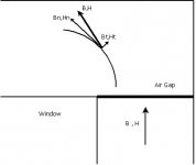
On second place, let's consider boundary conditions for B and H
(B₂ - B₁) ∙ n = 0
(H₂ - H₁) x n = 0
(H₂ - H₁) x n = 0
Let's perfectly clear, that the goal of this thread is to analyze our beloved transformers, so, pathological cases as that of your second graph will be avoided, after all we need them to listen music, not to magnetize all our neighborhood.
Furthermore, the scale of your picture, tells us that it is an EI375 core, i.e. 1.375" x 0.938" or about 35mm x 24mm, an air gap of 0.003"≈0.076mm looks reasonable, but an air gap of 0.053"≈1.35mm, seems insane for that core. What do you think?
With this proviso, and in order to design reasonably good transformers, we must achieve a negligible fringing flux, respect to the total flux, i.e. use as small as possible air gap.
Then, boundary conditions on the air gap, tell us that B remains unchanged in the air gap, because it is perpendicular to the air gap.
Changes on B, outside of the air gap, are due that B must pass through magnetic domains, and its tangential component changes, it is an effect due to core geometry/material, not due to the air gap!!!
Also, your interpretation of Fig.5. is wrong because you see one picture instead of the whole movie, let me explain
Let' consider paper's Fig.4.
On the lower trace, voltage goes from about 0.35V up to about 1.4V
On the upper trace, voltage goes from about 1.3V up to about 2.3V
Mind you that
Bac = (Uac x 10⁸) / (√2 π f S Np)
Then
Bac(upper trace) / Bac(lower trace) = 2.3V / 1.4V ≈ 1.64
Conclusion
Transformer was carried to saturation regardless of the air gap.
Attachments
Last edited:
I do not agree. By this line of thought if you remove the core completely, you will get 100% loss, yet end up with a linear air cored inductor. Core losses are fixed within the material and based on excitation level and frequency and air gaps do not change losses. The only thing the air gap does is modify the conditions that the core is working under.
Let's consider a transformer at no load, then we can write
Bac = (Uac x 10⁸) / (√2 π f S Np)
Hac = (4 √2 π Np ip) / (9 l)
Hac = (4 √2 π Np ip) / (9 l)
Any increase on ip implies an increase in H, then the integral
(1/8π) ∫B.H dV
Must be increased, so core losses must be increased.
You can think this increase as an increase of the energy wasted to maintain fields in the air gap
(1/8π) ∫B(Gap).H(Gap) dV(Gap)
Maybe you don't like the term "core loss" for this, so you can call it "gap loss" if you want, it is just semantic.
Last edited:
For the sake of the FEA it does not matter if you use DC or AC, as long as the flux density is the same the pattern of localized "Hot Spots" will be the same.
I see a series of pictures all with varying applied flux values. This is due to the fact that the current was kept constant and as the gap increased L went down requiring less voltage for a given current. This is shown in figure 4 and i see no value in these graphs in relation to the paper.
The only graph that makes any sense to me is Figure 9 where the AC voltage was kept constant and while the authors think the gap has a substantial effect on the losses, I don't interpret figure 9 as saying that. If the voltage were kept constant for the B field, again little difference would be seen.
Also, your interpretation of Fig.5. is wrong because you see one picture instead of the whole movie, let me explain
I see a series of pictures all with varying applied flux values. This is due to the fact that the current was kept constant and as the gap increased L went down requiring less voltage for a given current. This is shown in figure 4 and i see no value in these graphs in relation to the paper.
The only graph that makes any sense to me is Figure 9 where the AC voltage was kept constant and while the authors think the gap has a substantial effect on the losses, I don't interpret figure 9 as saying that. If the voltage were kept constant for the B field, again little difference would be seen.
You can change coordinate system, change the colors or even re-paint it but that doesn't change reality!
Agree, but to describe this reality you must do it with a reference, you must to put a coordinate system, and make that description in the right way.
Saturation does happen in localized areas when most of the core is still fine. I only posted this article because you were arguing that it is wrong to say that B is not uniform in the core.
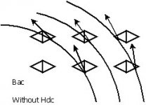
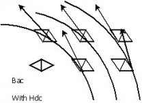
No, I did say that with a DC field Hdc, most magnetic domains become "pre aligned" and Hac has an easier task and then Bac result quite homogeneous.
Just in case, let me clarify that drawings are merely illustrative, and them try to explain the issue on areas where the field B tends to reduce due to unfavorable alignement of magnetic domains.
You can assume it uniform with good approximation only until saturation starts to happen which means MODERATE INDUCTION. Saturation will take place in local areas before the core is at the "nominal" saturation regardless of the gap! Of course the gap makes some difference on the evolution but it doesn't change the concept.
I agree, but partially, because you forgot the case of a DC current field previously applied.
Even more, in the case discussed on the paper, even under our modest equations, the core is quite saturated at Fig.5.(a), because, as I said before, seeing Fig.4.
Bac(upper trace) / Bac(lower trace) = 2.3V / 1.4V ≈ 1.64
If you look carefully the color bar, green has an error or tolerance of about 0.25T, then green color mean
Bac = (1 ± 0.25) T
We need to multiply by 1.64, then
Bac = (1 ± 0.25) T x 1.64
For a function of the form
f = a x b
The error in f, σ(f) is
σ(f) = √[(∂f/∂a)² σ(a)² + (∂f/∂b)² σ(b)²]
Supposing σ(b) = σ(a), we obtain
σ(Bac) = 0.35 T
Then
Bac = (1.64 ± 0.35) T
This value includes
Bac = 1.99 T
Then, at Fig.5.(a) the core is quite saturated, and under the scope of our modest equations, doesn't matter where is more saturated or less saturated, it is simply saturated.
Take the picture with correct gap for that DC current and signal and increase the signal and you will see that it happens again!
Honestly I don't understand what do you mean.

Analysis..???
We are talking here about the practical limit one can reach in terms of induction and what happens when induction is too high as this is where disagreement takes place.
My analysis obviously differ from your "practical limit", I said it many times, on different form, but, to be more clear, I will repeat that doesn't make sense to work an M6 EI core at Bmax=0.8 T, using for this, enormous cores, with less turns, that only destroy linearity, and make the calculations for fo=30 Hz !!!
Maybe does make more sense go to the consensed value of Bmax=1.3 T, or just go for a better lamination/core, and on both cases make the calculations for the lowest possible frequency. IMHO
In addition to the point made by Dave you also need to consider:
1) that is an article, it's not the final word. There are lots of them and this already means that there is not a unique answer, yet!
No, it is not just "an article", it is a scientific paper, published on an academic journal "PRZEGLĄD ELEKTROTECHNICZNY(Electrical Review)" supported by an university "Ibaraki University" and probably previously revised by a tribunal that mostly look for mistakes.
2) that is a simple inductor under sinusoidal excitation, where relative errors from measurements are actually non negligible.
The primary of a SE OPT is also a simple inductor, and measurement errors are inevitable. AFAIK
As a consequence of this you cannot build a castle on those maps. It was only to show you that flux density is not uniform from a rigorous point of view.
I showed you, from a rigorous point of view and a rough analysis, that with a SE OPT, the field Bac can be quite homogeneous, far before you posted that paper, and without build a castle on those maps.
Then an output transformer responding to a much more complex signal is surely more complicated. The kind of excitation alone already makes a difference, in particular for high induction.
Mind you that, derived equations, if used properly, can work with almost any kind of signal.
3) Answer to the question you avoided re-shuffling things.... :
When induction becomes high, above 1T, the history of the system under excitation becomes more and more important.
As if with "the history of the system under excitation" you mean magnetic anisotropy, mind you that I had been writing this from post#1
As for hysteresis losses, on post#234, I roughly showed that an enormous and badly designed transformer can have a worse behavior than of the humble design of post#71.
Attachments
Last edited:
For the sake of the FEA it does not matter if you use DC or AC, as long as the flux density is the same the pattern of localized "Hot Spots" will be the same.
From a point of view from physics, there is a great difference, but I have no idea about FEA, so, no comments.
I see a series of pictures all with varying applied flux values. This is due to the fact that the current was kept constant and as the gap increased L went down requiring less voltage for a given current. This is shown in figure 4 and i see no value in these graphs in relation to the paper.
No, the current was not kept constant, and precisely this is illustrated at Fig.4.
Four different measurements, but all of them graphed at the same current.
The only graph that makes any sense to me is Figure 9 where the AC voltage was kept constant and while the authors think the gap has a substantial effect on the losses, I don't interpret figure 9 as saying that. If the voltage were kept constant for the B field, again little difference would be seen.
Note that, increasing the air gap, "hot spots" are less, but "loss areas" became bigger.
No, the current was not kept constant, and precisely this is illustrated at Fig.4.
Four different measurements, but all of them graphed at the same current.
Fig. 4 shows how the V vs. I relationship follows the nonlinear relationship of the BH curve. Increase the gap and the system becomes more linear. It also points out that at the given 1A of excitation current used for Fig. 5 and Fig. 6 the excitation voltages are different so the flux is different resulting in the dramatic "apparent" changes.
Note that, increasing the air gap, "hot spots" are less, but "loss areas" became bigger.
The only image that is relevant is Fig. 9 where they attempt to normalize the AC, however they do not appear to take into account the fringing flux in the larger gap situation. Any flux occurring in air will reduce the flux in the core which seems like a simple explanation for the differences in Fig. 9
Fig. 4 shows how the V vs. I relationship follows the nonlinear relationship of the BH curve. Increase the gap and the system becomes more linear.
Totally agree !

It also points out that at the given 1A of excitation current used for Fig. 5 and Fig. 6 the excitation voltages are different so the flux is different resulting in the dramatic "apparent" changes.
Good point ! I did not pay much attention in Fig.6., is that I think slowly.
The only image that is relevant is Fig. 9 where they attempt to normalize the AC, however they do not appear to take into account the fringing flux in the larger gap situation. Any flux occurring in air will reduce the flux in the core which seems like a simple explanation for the differences in Fig. 9
Seems to me that for those small air gap, fringing flux should be negligible, but it is just my guess, I'm almost asleep to make any calculation...
Last edited:
Quite homogeneous means perfectly homogeneous for me. That is not the case! The gap helps but it won't make it perfect. There will also be areas where B will higher and once those become saturated they will quickly grow in volume. Saturation in a soft magnetic material doesn't happens suddenly even if you have the gap. Or do you want to insert a huge gap randomly just to prove your point?No, I did say that with a DC field Hdc, most magnetic domains become "pre aligned" and Hac has an easier task and then Bac result quite homogeneous.
I don't think you can do that so cheaply. Actually if you put the error bars in those graphs then you can't say anymore that the you have truly linear behaviour even with the 0.05 mm gap represented in fig.5d. For sure!I agree, but partially, because you forgot the case of a DC current field previously applied.
Even more, in the case discussed on the paper, even under our modest equations, the core is quite saturated at Fig.5.(a), because, as I said before, seeing Fig.4.
Bac(upper trace) / Bac(lower trace) = 2.3V / 1.4V ≈ 1.64
If you look carefully the color bar, green has an error or tolerance of about 0.25T, then green color mean
Bac = (1 ± 0.25) T
We need to multiply by 1.64, then
Bac = (1 ± 0.25) T x 1.64
For a function of the form
f = a x b
The error in f, σ(f) is
σ(f) = √[(∂f/∂a)² σ(a)² + (∂f/∂b)² σ(b)²]
Supposing σ(b) = σ(a), we obtain
σ(Bac) = 0.35 T
Then
Bac = (1.64 ± 0.35) T
This value includes
Bac = 1.99 T
Then, at Fig.5.(a) the core is quite saturated, and under the scope of our modest equations, doesn't matter where is more saturated or less saturated, it is simply saturated.
Honestly I don't understand what do you mean.
I was simply saying try to imagine what happens in fig. 5d when you increase Bac. It will start to get similar to the previous 5c (i.e. you will get saturated areas when most of the core is still fine). I say similar not identical!
Your analysis is wrong simply because I didn't tell EL156 to change core. Get over it!My analysis obviously differ from your "practical limit", I said it many times, on different form, but, to be more clear, I will repeat that doesn't make sense to work an M6 EI core at Bmax=0.8 T, using for this, enormous cores, with less turns, that only destroy linearity, and make the calculations for fo=30 Hz !!!
It's not about mistakes!! It's about research. It's a proposal rather than the truth.No, it is not just "an article", it is a scientific paper, published on an academic journal "PRZEGLĄD ELEKTROTECHNICZNY(Electrical Review)" supported by an university "Ibaraki University" and probably previously revised by a tribunal that mostly look for mistakes.
And that review has also a rather poor impact factor..... why didn't publish in a better journal?
You didn't show any map. You haven't included the real EI core anywhere.I showed you, from a rigorous point of view and a rough analysis, that with a SE OPT, the field Bac can be quite homogeneous, far before you posted that paper, and without build a castle on those maps.
Which equations? Didn't you know that your theory on big cores based onMind you that, derived equations, if used properly, can work with almost any kind of signal.
Steinmetz model is wrong? That model only works at moderate induction in sinusoidal regime! I hope you don't use an OT for listening to sinusoids!!
I can't see any relaxation process. Sorry!As if with "the history of the system under excitation" you mean magnetic anisotropy, mind you that I had been writing this from post#1
As for hysteresis losses, on post#234, I roughly showed that an enormous and badly designed transformer can have a worse behavior than of the humble design of post#71.
You did a bad design so you only proved that you are not able to.
Last edited:
How can you say that it is a bad design and he is not able too? The core was already there and not specially the choice of Popilin. He only made the best* out of it.
* its a matter of making choices and making compromisses. The best is not exist.
Would you use an EI150 core for a triode strapped EL34? It's just a bad design. You cannot prove your point going to extreme situations that are unrealistic and this is quite recurrent theme here!
I have never used EI 150 core for OT's, even for a 211 SE! Finding a good compromise requires common sense!
Last edited:
Seems to me that for those small air gap, fringing flux should be negligible, but it is just my guess, I'm almost asleep to make any calculation...
Instead it does make some difference! I have been telling you this since the beginning. The difference between me and you is that as I don't have proper software to run calculations on a realistic transformer and so I don't invent maps and theories but I know because I can measure other things that are strictly related. That's why I have been telling you for quite a while to make some transformers first. I am afraid Popilin you still have to "eat a lot of panini". There is no substitute for experience which is the first and most essential element in physics.
He also did a calculation for EI 84......
Quite homogeneous means perfectly homogeneous for me. That is not the case! The gap helps but it won't make it perfect. There will also be areas where B will higher and once those become saturated they will quickly grow in volume. Saturation in a soft magnetic material doesn't happens suddenly even if you have the gap. Or do you want to insert a huge gap randomly just to prove your point?
I don't think you can do that so cheaply. Actually if you put the error bars in those graphs then you can't say anymore that the you have truly linear behaviour even with the 0.05 mm gap represented in fig.5d. For sure!
I was simply saying try to imagine what happens in fig. 5d when you increase Bac. It will start to get similar to the previous 5c (i.e. you will get saturated areas when most of the core is still fine). I say similar not identical!
Your analysis is wrong simply because I didn't tell EL156 to change core. Get over it!
It's not about mistakes!! It's about research. It's a proposal rather than the truth.
And that review has also a rather poor impact factor..... why didn't publish in a better journal?
You didn't show any map. You haven't included the real EI core anywhere.
Which equations? Didn't you know that your theory on big cores based on
Steinmetz model is wrong? That model only works at moderate induction in sinusoidal regime! I hope you don't use an OT for listening to sinusoids!!
I can't see any relaxation process. Sorry!
You did a bad design so you only proved that you are not able to.
Would you use an EI150 core for a triode strapped EL34? It's just a bad design. You cannot prove your point going to extreme situations that are unrealistic and this is quite recurrent theme here!
I have never used EI 150 core for OT's, even for a 211 SE! Finding a good compromise requires common sense!
He also did a calculation for EI 84......
And so? My quote in post 369 referred to a precise post (post 234) where I can't see any EI 84 core. Please don't mix apples with oranges. But I already know that replying to you is hopeless.....
Last edited:
It started at post 49, 52, 60, If you are able and willing to read and not to hopeless.
Instead it does make some difference! I have been telling you this since the beginning. The difference between me and you is that as I don't have proper software to run calculations on a realistic transformer and so I don't invent maps and theories but I know because I can measure other things that are strictly related. That's why I have been telling you for quite a while to make some transformers first. I am afraid Popilin you still have to "eat a lot of panini". There is no substitute for experience which is the first and most essential element in physics.
And so? My quote in post 369 referred to a precise post (post 234) where I can't see any EI 84 core. Please don't mix apples with oranges. But I already know that replying to you is hopeless.....
I have never used EI 150 core for OT's, even for a 211 SE! Finding a good compromise requires common sense!
Without intention to offend you, but seems to me that this is not true, you did it, or at least you did say it
http://www.diyaudio.com/forums/tubes-valves/250569-transformer-test.html#post3806248
I have totally different design criteria, which is right or which is wrong, who can know it?
Without intention to offend you, but seems to me that this is not true, you did it, or at least you did say it
http://www.diyaudio.com/forums/tubes-valves/250569-transformer-test.html#post3806248
I have totally different design criteria, which is right or which is wrong, who can know it?
No Popillin, that was hypothetical. There is some difference between saying "I consider acceptable (in relation to the size of a 211 valve of course)" and " I have ever used". I have also never seen a 211 amplifier where such device was running at 120 mA! I have only used, to be precise re-cycled, that size for power supply. In fact this time I have to thank you, as you responded to yourself about one thing you have been wrongly attributing to me! It's not me using disproportionate cores.....
Last edited:
For normal M6 it will be between 0.7 and 0.9. Is it clear now why I always go for 0.75T total B at max Pout at 30Hz with EI core for best perfomance and 0.85T when I want to save in size and space?
For average M6, Bdc=0.40-0.43T depending on the gap (0.4 to 0.3 nominal, respectively)
In the SE OPT discussed here that uses normal M6 mu(dc) will be 330-350 depending on the actual gap to have 80 mA and will about 480-500 max around 0.8T. For simplicity assume 340. This gives Bdc just over 0.41T. It means that inductance will be max for Bac around 0.4T.
Then compute everything at 30Hz for 0.75-0.85T total B
At the end of the day, 0.75-0.85T @ 30Hz full output power
No Popillin, that was hypothetical.
Maybe the above is also hypothetical, but reflects your design choice. IMHO
There is some difference between saying "I consider acceptable (in relation to the size of a 211 valve of course)" and " I have ever used". I have also never seen a 211 amplifier where such device was running at 120 mA!
Maybe because that post, and that thread, was about of a 3K5/8 Ω transformer, and the venerable 211 was almost not mentioned along the whole thread.
No it's not. Of course it's my choice.Maybe the above is also hypothetical, but reflects your design choice. IMHO
Maybe because that post, and that thread, was about of a 3K5/8 Ω transformer, and the venerable 211 was almost not mentioned along the whole thread.
I don't need to explian . It's clear why I was saying that.....
Quite homogeneous means perfectly homogeneous for me.
When you use common language to describe a physical fact, you must be very careful with words.
Note that I did say (sic.) most magnetic domains become "pre aligned", because the material is magnetized by the external field Hdc.
If I had said "all magnetic domains become pre aligned in the same direction", would be close to description of saturation.
So, the field B graphed on Fig.5.(d) is quite homogeneous, if it were perfectly homogeneous would be all green!!!
That is not the case! The gap helps but it won't make it perfect.
I already said it on post#362, and I will repeat one more time
Changes on B, outside of the air gap, are due that B must pass through magnetic domains, and its tangential component changes, it is an effect due to core geometry/material, not due to the air gap!!!
I was simply saying try to imagine what happens in fig. 5d when you increase Bac. It will start to get similar to the previous 5c (i.e. you will get saturated areas when most of the core is still fine). I say similar not identical!
In Fig.5.(d) when you increase Bac, you will obtain something similar to Fig.5.(c), if you increase even more Bac, you will obtain something similar to Fig.5.(b), if you increase even more Bac, you will obtain something similar to Fig.5.(a)
But I still without understanding your point.
It's not about mistakes!! It's about research. It's a proposal rather than the truth.
And that review has also a rather poor impact factor..... why didn't publish in a better journal?
Curiously, when you posted that paper, was an absolute reference, what supposedly would prove that I was wrong.
Which equations? Didn't you know that your theory on big cores based on
Steinmetz model is wrong? That model only works at moderate induction in sinusoidal regime! I hope you don't use an OT for listening to sinusoids!!
No, I did say "derived equations", if Steinmetz empirical formula had been derived by me, it would be called "Popilín empirical formula"
Which is your proposal to evaluate hysteresis losses? Do you have a better equation?
If so, please post it.
I can't see any relaxation process. Sorry!
You can't see any relaxation process because you are seeing the movie at the wrong chair, let me explain
From the beginning of this thread, I had been saying that magnetic anisotropy imposes the fact that magnetic permeability must be a tensor.
As we have certain apprehension about tensors, was took a shortcut to use Classical Electrodynamics, without using tensors.
But if you want introduce a more precise description using Nuclear Magnetic Resonance, go ahead, I'm all ears.
Last edited:
- Status
- Not open for further replies.
- Home
- Amplifiers
- Tubes / Valves
- Design of transformers for valve amplifiers