Certainly just looking at pictures you'll never been able to tell how it really performs!how will you know? you haven't seen an actual transformer made by poppilin, nor me....
talk is cheap, it is the final product that counts.....")
I have been talking about the design of another one and more general considerations. What I know is that I measured at least 3 different types of standard GO EI cores and they were all similar (that's why I said mu eff will be 330-350 with that gap). The difference will not be like night and day changing brand. I try to be as rigorous as possible and not just guess and see if it works. If you don't believe it is not my problem. I don't need to demonstrate anything as anyone can verify it, assuming he can do it properly....
Manufacturers' datasheet refer to laminations sheets in the rolling direction not to EI cores, unless specified. Then there are treatments and tolerances when EI cores are made. They often refer to AST A-346 protocol which was dismissed 20 years ago for good reasons! One reason that came out recently? People demonstrated later that the average path length of that set-up needs to corrected for induction above 1T and so measurements are not so accurate as one might think. The higher the induction the stronger the correction.
Manufacturers' datasheet refer to laminations sheets in the rolling direction EVEN for EI cores.
https://www.edcorusa.com/t/Mtr-Core-Steel
As for "AST A-346 protocol" you mean ASTM standards perhaps?
ASTM International - Standards Worldwide
ASTM A346 - 74(1993)e1 Standard Test Method for Alternating Current Magnetic Performance of Laminated Core Specimens Using the Dieterly Bridge Method (Withdrawn 1998)
But them are not the only standards all over the world, e.g. Germans use DIN standards, Japanese use IEC standards, JEM and JIS (Japanese Industrial Standards), the list can be long...
Soon, probably they will be replaced by ISO standards, following your reasoning, all actual knowledge will be wrong because of a standard???
This is only bureaucracy, and I am more interested on transformers, if you don't care.
But....there is more. In EI cores the flux lines are basically along the rolling direction for about 2/3 of the path only, in the best case. Have you ever seen how permeability changes (decreases, to be precise) in any direction not parallel to the rolling one? Which is the worst direction?
Have you seen what the fringing flux does?
Can the induction be considered approx. uniform when B is no more moderate?
There will be areas where it will be poor and also areas where it will be quite higher, up to 40-50%, than average (Hint: inner corners, especially around the gap). When B is moderate these are just small hot spots at high induction. When B is high they will grow up in volume and saturation will take place even if most of the core is at safe levels! This explains why you can't assume mu AC constant up to saturation on the basis of design values. The design value for B in the basic equations does not reflect this.
No, I strongly disagree!!!
Maxwell's equations applies to macroscopic phenomena, they are also linear equations, so more than ever, linear superposition principle applies, and the vectorial sum of those "singularities" was already taken into account, then the transformer core as a whole has a well defined magnetic permeability, otherwise, magnetic hysteresis curve should not exists for the transformer as a whole.
But...there is more, and sorry to say that, but you did an extremely confused mess with fields B and H, let me explain
The normal component of field B doesn't change on any interface, normal component of field H does, so you confuse B with H, also you did mention flux, flux lines, induction and B, maybe it is just semantic, but, all those names are synonyms for the same thing, the magnetic field B!!! AFAIK
But...there is even more, apart for bother designers, the static field Hdc has a great utility that you forgot, its path is identical to that of Hac, and its great contribution is "pre align" most magnetic domains, then Hac follows the same path, but with magnetic domains "pre aligned" in its own direction, and Hac is quite homogeneous, except in the air gap, but all equations take this into account.
However, as I said before, on post#323, the work made by magnetic fields is incremented in those areas, so hysteresis loss and Barkhausen noise are also increased, because of an increase on rotation of magnetic domains, and has nothing to do with constancy of μ(AC) because the static field Hdc solve all the issue.
As for the fringing flux, the only region where is less negligible, is on the edges of the air gap, but again, it doesn't destroy the constancy of μ(AC), even more, this constancy is the result of the presence of an air gap!!!
As all equations are consistent, the design value for B is correct and well defined, except perhaps in your own new version of electromagnetism.
The design in post 71 will not work as you think because it is too optimistic. For standard EI laminations, that is what EL156 has, mueff is 330-350 using a 0.4 mm gap.
As I did say twice, I say it for third time
 the calculated value of μeff, depends on design choices, e.g. your own calculation gives 330-350, mine gives 481, and Yves program computed 783.
I have measured it.
Sorry, but I can't believe you.
I can believe you have a laboratory equipped with all kind of instruments, from a magnetometer to a NMR spectrometer.
But that I can't believe is you really has made the transformer of post#71
My numbers for permeability are REAL and MEASURED.
That mean you have winding the transformer of post#71? That's great! Your best contribution! Please post some measurements.
You never did it, so let me distrusting.
The basic formula to calculate the gap doesn't work well for EI cores. It needs corrections not only for the actual mu but also because of the fringing field.
Great! Can you please post that corrected version? Thanks.
The oscilloscope is not good for assessing distortion from a hysteresis curve. The only thing that it is clear is that the the C core of the Tango transformer is the only linear core in that link you posted previously. The oscilloscope is not even good to guess the amplifier distortion by looking at sinusoidal waves. When these still look good distortion is already some percents!
Maybe the oscilloscope is not good for assessing distortion from a hysteresis curve, but the little detail is that my proposal is only to see saturation, not distortion.
The only thing that it is clear is that the the C core of the "Tango" transformer is indeed a C core of a "Tamura" transformer.
Please stop to write nonsense, you are confusing people.
Last edited:
Indeed but . . .
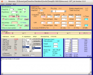
Showing just "BTot = 1.41T" picked from a part of my worksheet is meaningless as long as the power, the frequency and the DC primary are unknow.
BTW, the software does not impose any value even if it allows YOU to use what you want.
YOU are responsible for your choices.
"I'm not selling any alibies"
If the nails are bent, don't blame the hammer.
Yves.
I'm sorry if I offended you, was not my intention.
On post#52 you put this
I don't need any alibis, that I can't understand is the numbers were put by you, not by me, and them was not my choice, but yours...
Attachments
This is an example of permeability in all directions in grain oriented laminations....
The worst is at 45 degrees.
Beautiful picture, but I can't see magnetic permeability value at 0º
That's the absolute max and it doesn't mean necessarily best performance.
Even not considering that the typical well sorted valve amplifier is able to deliver much higher peak power than its RMS, when designing a transformer one also has to leave some headroom for DC current already. This not only because the actual DC current in quiescent conditions of the final amplifier can be different from its design values (or that transformer might be used for other applications) but also because the anode current often increases at full modulation! Pentodes in triode and UL connections with cathode bias are possibly the best candidates but it also happens with DHT's....so at least one has to allow for 10-15% more DC current respect to the design value even for specific applications.
At the end of the day, 0.75-0.85T @ 30Hz full output power (or 1-1.2T max @ 20Hz, if you like) is the practical max for best performance. The core choice is a consequence of all this and reasonable losses. Nothing like picking a random size. Make it smaller and performance at low frequency and/or insertion loss will be inevitably compromised.
Nihil sub sole novum, old recepies are still recommended.
No need that you insists on how destroy linearity.
Instead of use an enormous core, and less turns, maybe is better a higher grade lamination.
Nothing new under the sun.
Last edited:
popilin are there any threads on diyaudio with photos of your trannies ?
just to see what they look like physically.
I'm sorry, but I have no digital camera, however my cousin took some photos of my last set of amps/preamp.
When I have them, I will post on the sticky.
How meaningful is a plot of Iprimary vs Vprimary in assessing the capabilities of the core?
Bac(max) = (Uac x 10⁸) / (√2 π fo S Np)
Hac(max) = (4 √2 π Np iac) / (9 l)
Bac=f(Uac) Hac=f(iac)
Hac(max) = (4 √2 π Np iac) / (9 l)
Bac=f(Uac) Hac=f(iac)
Can this be used to determine the maximum usable Vprimary, when the primary winding is already in place?
Sorry, I don't understand your question, please clarify.
Last edited:
No, I strongly disagree!!!
Maxwell's equations applies to macroscopic phenomena, they are also linear equations, so more than ever, linear superposition principle applies, and the vectorial sum of those "singularities" was already taken into account, then the transformer core as a whole has a well defined magnetic permeability, otherwise, magnetic hysteresis curve should not exists for the transformer as a whole.
But...there is more, and sorry to say that, but you did an extremely confused mess with fields B and H, let me explain
The normal component of field B doesn't change on any interface, normal component of field H does, so you confuse B with H, also you did mention flux, flux lines, induction and B, maybe it is just semantic, but, all those names are synonyms for the same thing, the magnetic field B!!! AFAIK
But...there is even more, apart for bother designers, the static field Hdc has a great utility that you forgot, its path is identical to that of Hac, and its great contribution is "pre align" most magnetic domains, then Hac follows the same path, but with magnetic domains "pre aligned" in its own direction, and Hac is quite homogeneous, except in the air gap, but all equations take this into account.
However, as I said before, on post#323, the work made by magnetic fields is incremented in those areas, so hysteresis loss and Barkhausen noise are also increased, because of an increase on rotation of magnetic domains, and has nothing to do with constancy of μ(AC) because the static field Hdc solve all the issue.
As for the fringing flux, the only region where is less negligible, is on the edges of the air gap, but again, it doesn't destroy the constancy of μ(AC), even more, this constancy is the result of the presence of an air gap!!!
As all equations are consistent, the design value for B is correct and well defined, except perhaps in your own new version of electromagnetism.
Sorry I don't think so. Reality is a bit more complicated when one has to make things explicit in a specific case.
Then the rest of the world who run local field FEA analysis and represent flux density (in Tesla) throughout the core must be wrong....
Like this: http://pe.org.pl/articles/2011/9b/19.pdf
Last edited:
Can't you even read that picture? It's about 30000 @1.5T.Beautiful picture, but I can't see magnetic permeability value at 0º
No need that you insists on how destroy linearity.
Instead of use an enormous core, and less turns, maybe is better a higher grade lamination.
Nothing new under the sun.
Hogwash! The suggestion I gave to EL156 was simply to increase the number of turns accepting a bit higher insertion loss.
You are confusing me with someone else that uses huge cores and few turns to make insertion loss vanishingly small.....

Last edited:
Maybe the oscilloscope is not good for assessing distortion from a hysteresis curve, but the little detail is that my proposal is only to see saturation, not distortion.
Then you have no way to say that one solution is better than another one.
Does it change anything?The only thing that it is clear is that the the C core of the "Tango" transformer is indeed a C core of a "Tamura" transformer.

Please stop to write nonsense, you are confusing people.
Again!! Tell that to someone else!!!!
I always start from the assumption that people can understand and judge by themselves. Who do you think you are?
 Don't make me warn you guys again. The next personal shot will land the shooter in read-only mode.
Reality is a bit more complicated when one has to make things explicit in a specific case.
I must confess, that in this case I agree totally with you.
Then the rest of the world who run local field FEA analysis and represent flux density (in Tesla) throughout the core must be wrong....
Like this: http://pe.org.pl/articles/2011/9b/19.pdf
I strongly agree with that paper and their authors, even more, Fig.5 on page 3 (83) illustrate much better than me all what I have been saying.
Note that for an air gap = 0.001 mm, the field B is anything but homogeneous, Fig.5.(a)
For an air gap = 0.01 mm, the field B is still inhomogeneous, Fig.5.(b)
For an air gap = 0.025 mm, the field B only has very little inhomogeneities. Fig.5.(c)
Finally, for an air gap = 0.05 mm, the field B is quite homogeneous. Fig.5.(c)
That is what I have been saying from post#182 until now.
Core losses behavior, see Fig.6, is as predicted on post#323, and post#343
Conclusion
With an adequate air gap, μ(AC) is quite constant, magnetic fields are quite homogeneous, except H in the air gap as I said before sic "As for the fringing flux, the only region where is less negligible, is on the edges of the air gap"
As a consequence, linearity can be achieved.
Q.E.D.
Last edited:
I must confess, that in this case I agree totally with you.
I strongly agree with that paper and their authors, even more, Fig.5 on page 3 (83) illustrate much better than me all what I have been saying.
Note that for an air gap = 0.001 mm, the field B is anything but homogeneous, Fig.5.(a)
For an air gap = 0.01 mm, the field B is still inhomogeneous, Fig.5.(b)
For an air gap = 0.025 mm, the field B only has very little inhomogeneities. Fig.5.(c)
Finally, for an air gap = 0.05 mm, the field B is quite homogeneous. Fig.5.(c)
That is what I have been saying from post#182 until now.
Core losses behavior, see Fig.6, is as predicted on post#323, and post#343
Conclusion
With an adequate air gap, μ(AC) is quite constant, magnetic fields are quite homogeneous, except H in the air gap, and as a consequence, linearity can be achieved.
It's up to you to demonstrate it, above all EXPERIMENTALLY. And it's not just them.....Until then it's just your opinion.
Even in the figure with the bigger airgap you can see there are hot spots at the inner corners, easily B is 40-50% higher. As soon as induction is increased you get something quite worse. And that is only a 2D model. The real 3D is more likely worse.
Last edited:
It's up to you to demonstrate it, above all EXPERIMENTALLY.
Sorry, no, my duty here and the goal of this thread is another, already mentioned along the whole thread.
And it's not just them.....Until then it's just your opinion.
No, it is not just my opinion, is a physical fact, with solid theoretical foundation, and an amazing and unexpected experimental evidence.
Even in the figure with the bigger airgap you can see there are hot spots at the inner corners
That's why I did say: μ(AC) is quite constant, magnetic fields are quite homogeneous.
easily B is 40-50% higher.
No, if you look at the color code bar, that "hot spots" are in reality "cold spots" and is the other way around, there B is lower, not higher.
Sorry, no, my duty here and the goal of this thread is another, already mentioned along the whole thread.
No, it is not just my opinion, is a physical fact, with solid theoretical foundation, and an amazing and unexpected experimental evidence.
That's why I did say: μ(AC) is quite constant, magnetic fields are quite homogeneous.
No, if you look at the color code bar, that "hot spots" are in reality "cold spots" and is the other way around, there B is lower, not higher.
I said the inner corners! There are clearly yellow spots.
Then you should ask yourself why they do not try to explain what happens at higher induction as they measured up to saturation???
The answer is simple. Things gets a lot worse as you increase induction and you can't simply estimate core loss that way. So their model doesn't apply that well anymore. There is one thing that is negligible at moderate induction (i.e. up to just above 1T approx.) that becomes more and more relevant at higher induction. Can you guess what?
I said the inner corners! There are clearly yellow spots.
No, you did say
Even in the figure with the bigger airgap you can see there are hot spots at the inner corners, easily B is 40-50% higher.
The figure with the bigger air gap is Fig.5(d), if you put the coordinate system into the core, i.e. on the green zone, then you have defined eight corners, all of them "inner corners" on this case you have four "cold spots" on blue over four defined "inner corners"
If you put the coordinate system into the window, white/gray zone, you have defined four "inner corners", i.e. the window corners, and four "outer corners" i.e. the core's corners, on this case you have four "cold spots" at the "outer corners" and an homogeneous field at the "inner corners"
Then you are wrong, regardless of the coordinate system used.
Always you need to describe a given physical case, the first thing you must do is to put the coordinate system, i.e. the scenario where action elapses.
Then you should ask yourself why they do not try to explain what happens at higher induction as they measured up to saturation???
The answer is simple. Things gets a lot worse as you increase induction and you can't simply estimate core loss that way. So their model doesn't apply that well anymore.
No, it is not about that, the authors did a good job, the problem is not their model, but the way you attempt accommodate the paper's work to a given situation, i.e. a SE OPT.
Having read more carefully the paper, it is clear that transformer was used as a PP OPT, i.e. without a static DC field, the authors simply applied an AC voltage on the winding.
However, on Fig.4., we can clearly see the behavior of magnetic permeability, as the air gap is increased, μ decreases, up to the point it is quite constant and linearity is reached, i.e. V=f(i) is almost a straight line, be in mind that this condition implies B=f(H) is also almost a straight line.
The most important, is DC magnetic field was not applied, so predicted beneficial effect was not seen, and then losses are higher, and field B is not homogeneous at higher levels below saturation and smaller air gap.
Another thing to analyze is the core loss, however, Fig.8. is almost meaningless, because of measurements errors, see Table 1, and a scale factor that make corresponding values almost superposed.
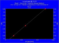
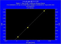
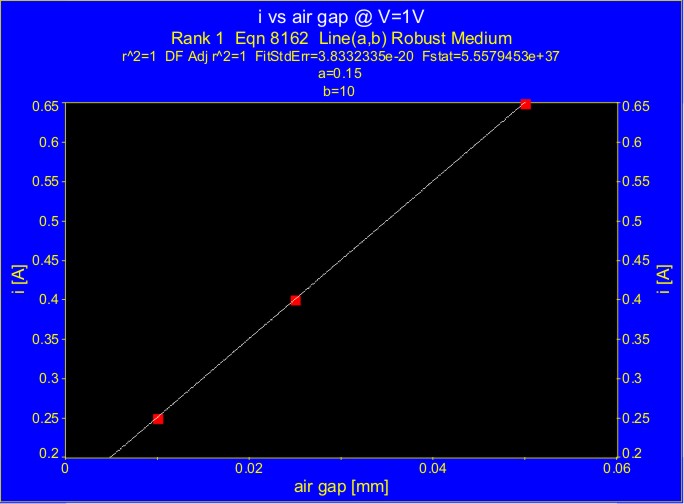
The way to see this, is making a graph i vs air gap, for different applied voltages.
Although we have only a few points, the analysis can be done.
The result is that, at no load, primary current increases with an increase of the air gap, because magnetic permeability decreases and also does primary inductance.
In other words, core losses increase with an increase of the air gap.
There is one thing that is negligible at moderate induction (i.e. up to just above 1T approx.) that becomes more and more relevant at higher induction. Can you guess what?
You should know that doesn't matter the answer.
Attachments
I strongly agree with that paper and their authors, even more, Fig.5 on page 3 (83) illustrate much better than me all what I have been saying.
I have a completely different take on this. Figure 5 simply shows that for DC, the addition of an airgap reduces the overall flux in the core. If one were to progrssively increase the DC current for samples with a larger gap to keep the B constant, the flux distribution through the core would be the same. As the gap increases, fringing flux will reduce the flux around the gap.
Below is a a FEA of an EI core with 0.003" gap and a 0.053" gap. The turns on the coils were adjusted to get the top halves of the cores to a similar range of flux densities to illustrate this.

The result is that, at no load, primary current increases with an increase of the air gap, because magnetic permeability decreases and also does primary inductance.
agreed.
In other words, core losses increase with an increase of the air gap.
I do not agree. By this line of thought if you remove the core completely, you will get 100% loss, yet end up with a linear air cored inductor. Core losses are fixed within the material and based on excitation level and frequency and air gaps do not change losses. The only thing the air gap does is modify the conditions that the core is working under.
No, you did say
The figure with the bigger air gap is Fig.5(d), if you put the coordinate system into the core, i.e. on the green zone, then you have defined eight corners, all of them "inner corners" on this case you have four "cold spots" on blue over four defined "inner corners"
If you put the coordinate system into the window, white/gray zone, you have defined four "inner corners", i.e. the window corners, and four "outer corners" i.e. the core's corners, on this case you have four "cold spots" at the "outer corners" and an homogeneous field at the "inner corners"
Then you are wrong, regardless of the coordinate system used.
You can change coordinate system, change the colors or even re-paint it but that doesn't change reality! Saturation does happen in localized areas when most of the core is still fine. I only posted this article because you were arguing that it is wrong to say that B is not uniform in the core.
You can assume it uniform with good approximation only until saturation starts to happen which means MODERATE INDUCTION. Saturation will take place in local areas before the core is at the "nominal" saturation regardless of the gap! Of course the gap makes some difference on the evolution but it doesn't change the concept. Take the picture with correct gap for that DC current and signal and increase the signal and you will see that it happens again!
No, it is not about that, the authors did a good job, the problem is not their model, but the way you attempt accommodate the paper's work to a given situation, i.e. a SE OPT.
Having read more carefully the paper, it is clear that transformer was used as a PP OPT, i.e. without a static DC field, the authors simply applied an AC voltage on the winding.
However, on Fig.4., we can clearly see the behavior of magnetic permeability, as the air gap is increased, μ decreases, up to the point it is quite constant and linearity is reached, i.e. V=f(i) is almost a straight line, be in mind that this condition implies B=f(H) is also almost a straight line.
The most important, is DC magnetic field was not applied, so predicted beneficial effect was not seen, and then losses are higher, and field B is not homogeneous at higher levels below saturation and smaller air gap.
Another thing to analyze is the core loss, however, Fig.8. is almost meaningless, because of measurements errors, see Table 1, and a scale factor that make corresponding values almost superposed.
The way to see this, is making a graph i vs air gap, for different applied voltages.
Although we have only a few points, the analysis can be done.

The result is that, at no load, primary current increases with an increase of the air gap, because magnetic permeability decreases and also does primary inductance.
In other words, core losses increase with an increase of the air gap.
You should know that doesn't matter the answer.
Analysis..???
We are talking here about the practical limit one can reach in terms of induction and what happens when induction is too high as this is where disagreement takes place.
In addition to the point made by Dave you also need to consider:
1) that is an article, it's not the final word. There are lots of them and this already means that there is not a unique answer, yet!
2) that is a simple inductor under sinusoidal excitation, where relative errors from measurements are actually non negligible. As a consequence of this you cannot build a castle on those maps. It was only to show you that flux density is not uniform from a rigorous point of view. Then an output transformer responding to a much more complex signal is surely more complicated. The kind of excitation alone already makes a difference, in particular for high induction.
3) Answer to the question you avoided re-shuffling things.... :
When induction becomes high, above 1T, the history of the system under excitation becomes more and more important. You can't simply calculate power loss that way, you need to add at least another time-depend term that takes this into account. Why time depend? What does this reflect?
- Status
- Not open for further replies.
- Home
- Amplifiers
- Tubes / Valves
- Design of transformers for valve amplifiers