Too big core for a PP OPT, try with EI 114 lamination.")
this is the question that's been bugging me,
how big is big?
a traffo with saturation spec at 10hz, will surely be huge compared to a traffo rated for 60hz saturation...
I didn't say anything different except that mu AC is not necessarily max at Bac max.
Agree, μ(AC) has not necessarily a maximum at Bac(max), but... you forget two details
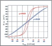
1- We have an air gap that affects both Hdc and Hac (increases them), so both μ(DC) and μ(AC) are greatly reduced, between one to two orders of magnitude, so magnetic hysteresis curve results less sloping, due to Bac does not change by the air gap, and the area inside the loop is almost constant, the new magnetic hysteresis curve is also thinner.
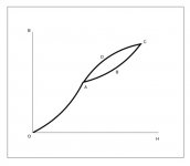
2- We have a superposition of two fields, DC and AC, we can apply linear superposition principle, then we have something like this
Bdc=f(Hdc) curve is from point O to A, Bac=f(Hac) curve is magnetic hysteresis loop, its path follows A-B-C-D-A points.
It results pretty clear that μ(AC) reaches a maximum at Bac(max).
If you do not like drawings, could be worse, could be tensor calculus...
However even mu DC in reality is not precisely constant as function of DC current. It will decrease a little bit with increasing current until where it drops suddenly.
We can consider μ(DC) constant only if steady state is reached, if steady state is not reached, μ(DC) will increase with Hdc (DC current) up its maximum, after that it will drops suddenly, (saturation) if Hdc (DC current) is reversed, due to anisotropy of magnetic domains, B=f(H) curve is reversed but following another path, this phenom is called magnetic hysteresis.
In the example here with 2080 turns, with 0.3 mm gap, it will be about 340 with 80 mA and will go up to 350 decreasing the current to 70 mA. This is just for the records.... Measuring mu(DC) with a very small (10 mT) AC field is the only "easy" way I know. Such small perturbation won't change things. It's classical physics regime....
You are guessing...again, without any calculation, neither lamination datasheet, these statements are only bluffing.
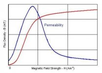
For average M6, Bdc=0.40-0.43T depending on the gap (0.4 to 0.3 nominal, respectively) with 2080 turns, 80 mA and 17.2 cm path length. With AC signal you can measure the inductance as function of signal (with 80 mA DC superimposed of course) and you will see that it initially increases, reaches a maximum and then starts to drop a long way before saturation.
Again, such claims without any proof is just chatter, but let me use my own crystal ball: I guess you are confused with PP OPTs, in this case you can have enormous variations on μ(AC), in a SE OPT such variations are a lot smaller.
As can be seen from drawing, Bac is dependent upon the applied Hac, the "knee" of the curve coincides with the point where μ(AC) starts to fall, in most cases for EI M6 between 10 KGauss to 12 KGauss, far from saturation region, as I said before, and you can check this with most manufacturers' datasheet.
Variations on μ(AC) are highly undesirable, and that behavior of Lp is indeed due to variations on μ(AC), however in a properly designed SE OPT with a very good core, μ(AC) can be about "constant" and magnetic hysteresis curve can tends to a "straight line" then your described behavior of Lp can be fruit of a very bad design.
I say "constant" rather than constant and "straight line" rather than straight line because of magnetic anisotropy.
Maybe you are confused because your obstination on use enormous EI cores, and very few turns to lower copper losses, this only make hysteresis losses sky high, same with magnetizing current, and as a bonus, magnetic hysteresis curve is very thick, that's the reason for your large variations on μ(AC).
Verify where you get the max and see if this is the max Pout you assumed at 20Hz...
I don't think so.
No, you are still confused, the goal is not a maximum in μ(AC), the goal is keep it constant!!!
Attachments
Last edited:
this is the question that's been bugging me,
how big is big?
a traffo with saturation spec at 10hz, will surely be huge compared to a traffo rated for 60hz saturation...
On post#73 I gave you an answer, but if serves for something, I'll try again.
If the wire fits into the window, the core is enough, if doesn't, the core is too small, if left much free space in the window, the core is too big, as I said before is more an art than a science, and it depends a lot on experience.
 now i particularly like your last sentence....
Here is a measurement:
http://plitron.com/wp-content/uploads/Atcl_3.pdf
In Fig.7 you have the primary inductance (measured at 25H while the standard is usually 50Hz) as function of secondary voltage. Although this is a PP OPT and the variation in mu is much more than in a SE OPT with gap you can see that L is max for 9 V rms only. 9 V rms into 5R is about 16W. That transformer is specified for 100W and power bandwidth (-3dB and so 50W) at 22.7 Hz.
In this case it is not a problem because the primary inductance is huge anyway although it is supposed that there is no unbalance so if you want to make use of it you need a bias servo as he did otherwise you need a gap and things might change....
So, your source of inspiration is a poorly written article, with badly written equations that can't pass even a dimensional consistency analysis, and about... Push-Pull transformers!!!

Inductance expresion in cgs units has the form
L = (4 π μ S N²) / (9 lm x 10⁸)
Where
μ is the magnetic permeability of the core (dimensionless)
S is the effective cross sectional area of the core in cm²
N is the number of turns
lm is the magnetic path lenght in cm
In mks units
L = (μo μr A N²) / lm
Where
μo is the vacuum permeability
μr is the relative permeability of the core
A is the effective cross sectional area of the core in m²
N is the number of turns
lm is the magnetic path lenght in m
In the "reference" article, in the beginning of an analysis about Ls, formula (3)
Ls = (μo μr Ns² lm) / A
No words...
In the SE OPT discussed here that uses normal M6 mu(dc) will be 330-350 depending on the actual gap to have 80 mA
No, μeff≈481 @ 80 mA, 330-350 are random numbers.
and will about 480-500 max around 0.8T.
No, here you confuse again μ, μ(AC), μ(DC), and that maximum not necessarily will be at 0.8 T, with most M6 lamination is in the 10 KGauss-12 KGauss region, do you have the datasheet for that particular core?
For simplicity assume 340.
Of course, for simplicity you also can assume any other random number.
This gives Bdc just over 0.41T.
Ah, now I can see, the choice was for convenience, for poor results.
It means that inductance will be max for Bac around 0.4T.
No, you are still confused, the idea (if any good) behind the article is that μ, in our case μ(AC), must be constant, not the absolute maximum of the lamination.
How much power is this at 20Hz into 3K primary load? It is less 2.4W. Above this output inductance will be more or less constant for just a bit and then decrease. So the effective impedance will be lower and lower and distiortion increases.
There is a big difference between a calculation and a guess, so far I didn't see any calculation from you, except perhaps 2.4W at 20Hz and 0.4T, and that come from here
Bac(max) = (Uac x 10⁸) / (√2 π fo S Np)
And with another false assumption, because Bac(max) = 8000 Gauss = 0.8 T
And with another false assumption, because Bac(max) = 8000 Gauss = 0.8 T
This core is simply not suitable for a 3K SE OPT that can deliver 10W at 20Hz with 80 mA DC and low distortion while scoring reasonable numbers in the other departments as well. It's not rocket science.
Maybe, but until you can prove it, your guesses, based on false assumptions doesn't help too much.
Maybe prove it, is rocket science after all.
Last edited:
Damn...was a trap to say "experience"
Damn...was a trap to say "experience"
actually i liked the part when you say "more of an art than science"....
Are there any really great SPICE models for audio transformers? I use Tina, and it does have a long list of parameters I can specify, but I don't have a clue about almost all of them. Does it appear that enough parameters are included in the Tina spice model of a transformer?
Technically possible but you have to measure L/mu(AC, DC) curves and convert them somehow to SPICE formulas (I don't know how). So there are no "universal" model.
I simulated in LTSpice different PP circuits (with THD analysis), and got simulation results very close to real life.
Parameters used: primary/secondary inductance (assumed to be constant in SPICE), R(DC) of both windings, coupling factor. Unless design of your real transformer is not seriously flowed, that's seem to be enough.
SPICE won't predict sonic signature and its someone psychoacoustic perception anyway.
Technically possible but you have to measure L/mu(AC, DC) curves and convert them somehow to SPICE formulas (I don't know how). So there are no "universal" model.
I simulated in LTSpice different PP circuits (with THD analysis), and got simulation results very close to real life.
Parameters used: primary/secondary inductance (assumed to be constant in SPICE), R(DC) of both windings, coupling factor. Unless design of your real transformer is not seriously flawed, that's seem to be enough.
SPICE won't predict sonic signature and its someone psychoacoustic perception anyway.
OK, thanks a lot.
I've been using the ones that came with Tina for a long time now. I can't directly specify inductance in their model. I can only specify core dimension, type of core, turns ratio, and many other things. So, some of the specifications i specify in the models are just guesses.
Agree, μ(AC) has not necessarily a maximum at Bac(max), but... you forget two details
1- We have an air gap that affects both Hdc and Hac (increases them), so both μ(DC) and μ(AC) are greatly reduced, between one to two orders of magnitude, so magnetic hysteresis curve results less sloping, due to Bac does not change by the air gap, and the area inside the loop is almost constant, the new magnetic hysteresis curve is also thinner.

2- We have a superposition of two fields, DC and AC, we can apply linear superposition principle, then we have something like this

Bdc=f(Hdc) curve is from point O to A, Bac=f(Hac) curve is magnetic hysteresis loop, its path follows A-B-C-D-A points.
It results pretty clear that μ(AC) reaches a maximum at Bac(max).
If you do not like drawings, could be worse, could be tensor calculus...
We can consider μ(DC) constant only if steady state is reached, if steady state is not reached, μ(DC) will increase with Hdc (DC current) up its maximum, after that it will drops suddenly, (saturation) if Hdc (DC current) is reversed, due to anisotropy of magnetic domains, B=f(H) curve is reversed but following another path, this phenom is called magnetic hysteresis.
You are guessing...again, without any calculation, neither lamination datasheet, these statements are only bluffing.
Again, such claims without any proof is just chatter, but let me use my own crystal ball: I guess you are confused with PP OPTs, in this case you can have enormous variations on μ(AC), in a SE OPT such variations are a lot smaller.

As can be seen from drawing, Bac is dependent upon the applied Hac, the "knee" of the curve coincides with the point where μ(AC) starts to fall, in most cases for EI M6 between 10 KGauss to 12 KGauss, far from saturation region, as I said before, and you can check this with most manufacturers' datasheet.
Variations on μ(AC) are highly undesirable, and that behavior of Lp is indeed due to variations on μ(AC), however in a properly designed SE OPT with a very good core, μ(AC) can be about "constant" and magnetic hysteresis curve can tends to a "straight line" then your described behavior of Lp can be fruit of a very bad design.
I say "constant" rather than constant and "straight line" rather than straight line because of magnetic anisotropy.
Maybe you are confused because your obstination on use enormous EI cores, and very few turns to lower copper losses, this only make hysteresis losses sky high, same with magnetizing current, and as a bonus, magnetic hysteresis curve is very thick, that's the reason for your large variations on μ(AC).
No, you are still confused, the goal is not a maximum in μ(AC), the goal is keep it constant!!!
My numbers for permeability are REAL and MEASURED. And permeability will never be constant. Its variation is only reduced with the gap and it not max at a generic Bmax. It depends on the material, the gap and where you are. You generic pictures and tentatives show that your experience is ZERO!!
The goal is to get the best possible behaviour which means 2*pi*f*L >> Req. It 's obvious that this is desirable at max power. Only this will minimize distortion as in SE amplifiers the inductance is always limited. Your problem is that you have no idea about audio amplifiers!
Moreover working at lower B max one also gets lower core loss. But you are so smart that couldn't realize this until now that I am telling you!!
Keep you considerations about my designs for you has you know nothing. What you write is absolutely WRONG!
Last edited:
Hi 45 !!!
I can see that you disagree with popilin, and popilin disagrees with you, so i make a chalenge for you ! With the core i have, popilin made me the calculations for a EL34 SE , 3K , 80 Ma, sec 8 ohms. Would you like to make your own calculations, and i will wind both transformers and check wich one give me the best results ?
Thanks
Hi 45 !!!
I can see that you disagree with popilin, and popilin disagrees with you, so i make a chalenge for you ! With the core i have, popilin made me the calculations for a EL34 SE , 3K , 80 Ma, sec 8 ohms. Would you like to make your own calculations, and i will wind both transformers and check wich one give me the best results ?
Thanks
Your core is not suitable for 10W at 20Hz, acutaly not even at 30Hz for me, with low distortion having 80 mA DC and 3K impedance. You have to accept lower power below 35-40Hz if you want a transformer that is good also in the other departments. No need for other designs just be aware of that (i.e. below that frequency distortion will be higher and higher in comparison to 100Hz already) and the fact that the number of turns you can put in each layer is lower that he wrote...having no idea.....
You can verify what I am saying just measuring the FR with very small signal and at 1W and higher power level and you' ll see that is not precisely the same.
Last edited:
No, you are still confused, the goal is not a maximum in μ(AC), the goal is keep it constant!!!
Stop telling I am confused. You are the only one making mistakes. The other main point was that you got a completely wrong value for Bdc confusing dc values with ac values.
Then as soon as Bac is 50-100 Gauss mu AC increases a lot and then it changes very little for quite a bit. The goal is to have it at its max at max Pout. This is not the case if your total B is 1.6T. You can say is constant, almost constant or any other word but it will change and when you are still away from what is defined as saturation it will not be anymore. Here permeability becomes lower and lower. 1.6T for EI is simply BAD!
Do you want to bet?
Last edited:

I think we should understand that English is probably not Popilin's native language and therefore he may not intend to say what some of us thinks he's saying.
It's not mine either. Certain things are really not related to language like the actual value of Bdc and how inductance behaves as function of signal. That is just about not knowing the real thing!!
- Status
- Not open for further replies.
- Home
- Amplifiers
- Tubes / Valves
- Design of transformers for valve amplifiers