what i do is compute for the 60hz power capacity and scale it down to say 20hz...so that if a core can do 300 watts at 60hz then is is probably good for 100 watts at 20 hz....i know this is too simplistic but it is a start, maybe you can investigate further....
OK, let's investigate a bit
With a rule of dumb we compute, 300 W at 60 Hz and say 14500 Gauss
S = 1000 √(P / fo Bmax) ≈ 19 cm²
So an EI 120/50 with 0.95 stacking factor seems OK, then
μeff = (9 η fo l S Bac²) / (4 P x 10⁸) ≈ 410
Same S ≈ 19 cm², with 100 W at 20 Hz and 14500 Gauss.
Then it should works with a PP OPT, with μeff ≈ 410 at maximum power, but another thing is a SE OPT, at say Bac = 8000 Gauss, Bdc = 6500 Gauss
S ≈ 62 cm²
With the same core, i.e. S ≈ 19 cm², μeff ≈ 410, at 20 Hz you only could obtain
P = (9 η fo l S Bac²) / (4 μeff x 10⁸) ≈ 30 W
Last edited:
Emails from my friend Martin, and a long discussion with my friend Osvaldo, convinced me that my drawings are confusing.
Perhaps drawings are wright, but misinterpretation of them gets confused to the reader. In fact, for me was a bit difficult to understand, because I used Superposition Theorem not for this topic specially.
Tip#13 C vs EI
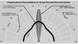
Let's consider now the most common shapes for transformer cores, we suppose GOSS lamination.
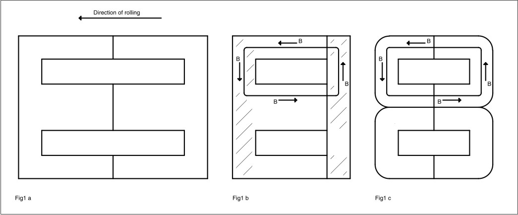
On Fig 1 a, we can see the waste-less pattern for most commercial EI lamination, as a consequence of magnetic domains orientation are mostly coincident with the direction of rolling, on Fig1 b it can be seen the issue with an applied field B.
Clearly it can be seen that over shaded area, the direction of B is not perfectly coincident with the direction of magnetic domains, and over more unfavored zone both directions are perpendicular.
As consequence, the work made by magnetic fields is incremented in those areas, so hysteresis loss is also increased.
Even on NOSS, when applied field B is deviated from the direction of rolling i.e. from 0º to 90º, increases Barkhausen noise.
On a C core, the direction of field B is mostly coincident with the direction of rolling, and then with the orientation of magnetic domains, consequently can be minimized both, hysteresis losses and Barkhausen noise.
I already mentioned that with C cores, can be used ridiculously thin lamination, and eddy current losses can be also reduced.
Let's consider now the most common shapes for transformer cores, we suppose GOSS lamination.
On Fig 1 a, we can see the waste-less pattern for most commercial EI lamination, as a consequence of magnetic domains orientation are mostly coincident with the direction of rolling, on Fig1 b it can be seen the issue with an applied field B.
Clearly it can be seen that over shaded area, the direction of B is not perfectly coincident with the direction of magnetic domains, and over more unfavored zone both directions are perpendicular.
As consequence, the work made by magnetic fields is incremented in those areas, so hysteresis loss is also increased.
Even on NOSS, when applied field B is deviated from the direction of rolling i.e. from 0º to 90º, increases Barkhausen noise.
On a C core, the direction of field B is mostly coincident with the direction of rolling, and then with the orientation of magnetic domains, consequently can be minimized both, hysteresis losses and Barkhausen noise.
I already mentioned that with C cores, can be used ridiculously thin lamination, and eddy current losses can be also reduced.
Attachments
Last edited:
Tip#14 Zero Crossing
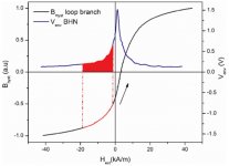
Maybe is a truism, but surprisingly, higher movability of magnetic domains it produces when field B has a zero crossing, B=0 on magnetic hysteresis curve, i.e. vector B changes its sense of direction.

On that case, Barkhausen noise, BHN, reaches its maximum, and achilles heel of SE OPTs becomes on its major advantage, because due to static field Bdc, Bac hysteresis loop will avoid zero crossing.
Maybe is a truism, but surprisingly, higher movability of magnetic domains it produces when field B has a zero crossing, B=0 on magnetic hysteresis curve, i.e. vector B changes its sense of direction.
On that case, Barkhausen noise, BHN, reaches its maximum, and achilles heel of SE OPTs becomes on its major advantage, because due to static field Bdc, Bac hysteresis loop will avoid zero crossing.
Attachments
Perhaps drawings are wright, but misinterpretation of them gets confused to the reader. In fact, for me was a bit difficult to understand, because I used Superposition Theorem not for this topic specially.
High level of abstraction!
Slowly getting to the point but still missing some fundamental "details"! Maybe in the next 322 posts it will be clear why EI cores cannot run at 1.6T like C cores....
My apologies, is that I think slowly...
That's a great idea! I thought I had already covered all doubts.
Thank you very much.
Tip#15 How far can work an EI GOSS core?
1) Simple method
See the manufacturer datasheet, do a statistical treatment with the data in order to obtain μeff as a function of B, as I did on post#231, be carefull to use cgs units(*) mostly for μeff, doesn't care if B is expressed in Gauss or Tesla, look for the value of B that ensures you about 1% constancy for μeff, below saturation of course.
(*) If you use mks units for μ, as most datasheets does, you will obtain WRONG results, before data processing you MUST divide μ from datasheet, by
Where: N A⁻² are annoying mks units, doesn't matter.
As a rule of dumb you must obtain for μ, five digit numbers.
A very good tool is the windows version of an old DOS program, it is free trial and easy to use
TC2D.zip
Bad news is that most manufacturers give the data of "crude" lamination; after it was cutted, magnetic domains suffers a change, and a posterior treatment is needed to "realign" them and/or remove mechanical stress.
That does not mean lamination manufacturers are evil, but in most cases, simply they do not cut the lamination.
2) Then you can go the hard way, DIY
Warning! This is an almost destructive test, using
Make a winding with a generously thick wire to minimize copper losses, and build the core with E's and I's interleaved one by one, I mean an E over an I and so on, be sure that they fit firmly, with a piece of softwood and a hammer be sure that each E and each I are as close as possible in order to reduce the air gap to a minimum, don't worry if you must hit it hard, that's normal.
With an insulated variac i.e. with separate primary and secondary for safety, put an AC voltage on the winding, like is illustrated here
View A Transformer's Hysteresis Curve With An Ultra-Simple Circuit | Test & Measurement content from Electronic Design
The oscilloscope is used only to see saturation, the most important measurement is Uac (VRMS), with this measured value below saturation, you can now calculate B below saturation.
The general consensus for standard M6 lamination is
But not all laminations are equal, if you know that your lamination is good, you can go so far as about 1.41 T, as Yvesm did on his program
As the saying goes: the tiger has many stripes, one more will not make any noticeable difference.
On post#71, I myself went up to 1.45 T, but knowing that lamination is below saturation.
Once, I used an unknown MXX lamination up to 1.38 T with amazing results, unfortunately I have no proof...
1) Simple method
See the manufacturer datasheet, do a statistical treatment with the data in order to obtain μeff as a function of B, as I did on post#231, be carefull to use cgs units(*) mostly for μeff, doesn't care if B is expressed in Gauss or Tesla, look for the value of B that ensures you about 1% constancy for μeff, below saturation of course.
(*) If you use mks units for μ, as most datasheets does, you will obtain WRONG results, before data processing you MUST divide μ from datasheet, by
μ0 = 4π × 10⁻⁷ N A⁻²
Where: N A⁻² are annoying mks units, doesn't matter.
As a rule of dumb you must obtain for μ, five digit numbers.
A very good tool is the windows version of an old DOS program, it is free trial and easy to use
TC2D.zip
Bad news is that most manufacturers give the data of "crude" lamination; after it was cutted, magnetic domains suffers a change, and a posterior treatment is needed to "realign" them and/or remove mechanical stress.
That does not mean lamination manufacturers are evil, but in most cases, simply they do not cut the lamination.
2) Then you can go the hard way, DIY
Warning! This is an almost destructive test, using
Bac(max) = (Uac x 10⁸) / (√2 π fo S Np)
Make a winding with a generously thick wire to minimize copper losses, and build the core with E's and I's interleaved one by one, I mean an E over an I and so on, be sure that they fit firmly, with a piece of softwood and a hammer
be sure that each E and each I are as close as possible in order to reduce the air gap to a minimum, don't worry if you must hit it hard, that's normal.With an insulated variac i.e. with separate primary and secondary for safety, put an AC voltage on the winding, like is illustrated here
View A Transformer's Hysteresis Curve With An Ultra-Simple Circuit | Test & Measurement content from Electronic Design
The oscilloscope is used only to see saturation, the most important measurement is Uac (VRMS), with this measured value below saturation, you can now calculate B below saturation.
The general consensus for standard M6 lamination is
Bmax = Bdc + Bac = 13000 Gauss = 1.3 T
But not all laminations are equal, if you know that your lamination is good, you can go so far as about 1.41 T, as Yvesm did on his program
As the saying goes: the tiger has many stripes, one more will not make any noticeable difference.
On post#71, I myself went up to 1.45 T, but knowing that lamination is below saturation.
Once, I used an unknown MXX lamination up to 1.38 T with amazing results, unfortunately I have no proof...
Attachments

Last edited:
@poppilin, have you seen EI's made out of M2's?
Only in my dreams and a few datasheets.
Here I only can obtain unknown MXX, and with luck and favorable wind, it would result, as much, an M6.
However, also exists HiB Z grade, even for EI, and you can go easily up to 1.6 T or more, well below saturation.
over here i use z11(m6) cores for opt's but it costs about U$10 per kilogram, i also use M18, same thickness as z11 at 0.35mm or gage #29 and costs about U$4 per kilo, the H50 cores gage 24 or 0.5mm thick cost just over a dollar a kilo...
otoh, if you know how to look at cores, you can get them for less than a dollar a kilo in the surplus or recyclers', but supply is at the most iffy.....
otoh, if you know how to look at cores, you can get them for less than a dollar a kilo in the surplus or recyclers', but supply is at the most iffy.....
over here i use z11(m6) cores for opt's but it costs about U$10 per kilogram, i also use M18, same thickness as z11 at 0.35mm or gage #29 and costs about U$4 per kilo, the H50 cores gage 24 or 0.5mm thick cost just over a dollar a kilo...
otoh, if you know how to look at cores, you can get them for less than a dollar a kilo in the surplus or recyclers', but supply is at the most iffy.....
You really has lucky.
I have few choices, but I prefer new lamination at any grade, because of mechanical stress that alter magnetic properties, and deformation that makes extremely difficult to achieve desired stacking factor, not to mention vibration noise due to magnetostriction.
Even so, I usually must buy double than necessary, because of the cut, scratches, and little deformities, after that, I must clean all E's and I's with thinner, to eliminate oil, one by one!

With new, clean, and selected lamination, is easier to glue them each other, I hate that transformers sing by themselves.
BTW, surely should exist a cross reference between M and Z grades, but I don't know it, and as you can see doesn't matter so much over here.
Sometimes I feel like as I live in Gilligan's Island, and I must build amplifiers with coconuts!
Last edited:
Tip#15 How far can work an EI GOSS core?
1) Simple method
See the manufacturer datasheet, do a statistical treatment with the data in order to obtain μeff as a function of B, as I did on post#231, be carefull to use cgs units(*) mostly for μeff, doesn't care if B is expressed in Gauss or Tesla, look for the value of B that ensures you about 1% constancy for μeff, below saturation of course.
(*) If you use mks units for μ, as most datasheets does, you will obtain WRONG results, before data processing you MUST divide μ from datasheet, by
μ0 = 4π × 10⁻⁷ N A⁻²
Where: N A⁻² are annoying mks units, doesn't matter.
As a rule of dumb you must obtain for μ, five digit numbers.
A very good tool is the windows version of an old DOS program, it is free trial and easy to use
TC2D.zip
Bad news is that most manufacturers give the data of "crude" lamination; after it was cutted, magnetic domains suffers a change, and a posterior treatment is needed to "realign" them and/or remove mechanical stress.
That does not mean lamination manufacturers are evil, but in most cases, simply they do not cut the lamination.
2) Then you can go the hard way, DIY
Warning! This is an almost destructive test, using
Bac(max) = (Uac x 10⁸) / (√2 π fo S Np)
Make a winding with a generously thick wire to minimize copper losses, and build the core with E's and I's interleaved one by one, I mean an E over an I and so on, be sure that they fit firmly, with a piece of softwood and a hammer
With an insulated variac i.e. with separate primary and secondary for safety, put an AC voltage on the winding, like is illustrated here
View A Transformer's Hysteresis Curve With An Ultra-Simple Circuit | Test & Measurement content from Electronic Design
The oscilloscope is used only to see saturation, the most important measurement is Uac (VRMS), with this measured value below saturation, you can now calculate B below saturation.
The general consensus for standard M6 lamination is
Bmax = Bdc + Bac = 13000 Gauss = 1.3 T
But not all laminations are equal, if you know that your lamination is good, you can go so far as about 1.41 T, as Yvesm did on his program
As the saying goes: the tiger has many stripes, one more will not make any noticeable difference.
On post#71, I myself went up to 1.45 T, but knowing that lamination is below saturation.
Once, I used an unknown MXX lamination up to 1.38 T with amazing results, unfortunately I have no proof...
Manufacturers' datasheet refer to laminations sheets in the rolling direction not to EI cores, unless specified. Then there are treatments and tolerances when EI cores are made. They often refer to AST A-346 protocol which was dismissed 20 years ago for good reasons! One reason that came out recently? People demonstrated later that the average path length of that set-up needs to corrected for induction above 1T and so measurements are not so accurate as one might think. The higher the induction the stronger the correction.
But....there is more. In EI cores the flux lines are basically along the rolling direction for about 2/3 of the path only, in the best case. Have you ever seen how permeability changes (decreases, to be precise) in any direction not parallel to the rolling one? Which is the worst direction?
Have you seen what the fringing flux does?
Can the induction be considered approx. uniform when B is no more moderate?
There will be areas where it will be poor and also areas where it will be quite higher, up to 40-50%, than average (Hint: inner corners, especially around the gap). When B is moderate these are just small hot spots at high induction. When B is high they will grow up in volume and saturation will take place even if most of the core is at safe levels! This explains why you can't assume mu AC constant up to saturation on the basis of design values. The design value for B in the basic equations does not reflect this.
The design in post 71 will not work as you think because it is too optimistic. For standard EI laminations, that is what EL156 has, mueff is 330-350 using a 0.4 mm gap. I have measured it.
The basic formula to calculate the gap doesn't work well for EI cores. It needs corrections not only for the actual mu but also because of the fringing field.
The oscilloscope is not good for assessing distortion from a hysteresis curve. The only thing that it is clear is that the the C core of the Tango transformer is the only linear core in that link you posted previously. The oscilloscope is not even good to guess the amplifier distortion by looking at sinusoidal waves. When these still look good distortion is already some percents!
Last edited:
The general consensus for standard M6 lamination is
Bmax = Bdc + Bac = 13000 Gauss = 1.3 T
But not all laminations are equal, if you know that your lamination is good, you can go so far as about 1.41 T, as Yvesm did on his program
That's the absolute max and it doesn't mean necessarily best performance.
Even not considering that the typical well sorted valve amplifier is able to deliver much higher peak power than its RMS, when designing a transformer one also has to leave some headroom for DC current already. This not only because the actual DC current in quiescent conditions of the final amplifier can be different from its design values (or that transformer might be used for other applications) but also because the anode current often increases at full modulation! Pentodes in triode and UL connections with cathode bias are possibly the best candidates but it also happens with DHT's....so at least one has to allow for 10-15% more DC current respect to the design value even for specific applications.
At the end of the day, 0.75-0.85T @ 30Hz full output power (or 1-1.2T max @ 20Hz, if you like) is the practical max for best performance. The core choice is a consequence of all this and reasonable losses. Nothing like picking a random size. Make it smaller and performance at low frequency and/or insertion loss will be inevitably compromised.
Nihil sub sole novum, old recepies are still recommended.
Last edited:
Indeed but . . .
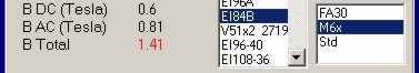
Showing just "BTot = 1.41T" picked from a part of my worksheet is meaningless as long as the power, the frequency and the DC primary are unknow.
BTW, the software does not impose any value even if it allows YOU to use what you want.
YOU are responsible for your choices.
"I'm not selling any alibies"
If the nails are bent, don't blame the hammer.
Yves.
Last edited:
blame the hammerer instead....
45 and poppilin can argue "ad absurdum", ad hominem, ad infinitum, or whatever, i still make my own traffos the way i like to......just like Yvesm told.....
With the "unimportant" difference that I am not alone. Of course you can do them the way you like but this has very little to do with general considerations about design. When someone else will ask you how you would do this and that you'll need to have a safe and proper procedure to give a good advice. Being just a little bit conservative will guarantee that it will work at least with some minimal flexibility and if core quality is better than average it will be better. It is just as simple as that.
how will you know? you haven't seen an actual transformer made by poppilin, nor me....
talk is cheap, it is the final product that counts.....
for this thread to be more meaningful, i would like to see more discussions about,
core material availability, bobbins, insulation materials, plastics and papers, termination details,
mounting and housing, actual pictures of products for all to see....
- Status
- Not open for further replies.
- Home
- Amplifiers
- Tubes / Valves
- Design of transformers for valve amplifiers