Z windings really help downloading capacitance. In a obscure project I'm working on, it helped me too much, as to reduce capacitance almost 3 times less.
Agree, Z winding works, because reduce the gradient of voltage along adjacent layers, but as I said before, if you have many primary windings, that in turn have many layers, is a nightmare to winding.

Certainly, Popilin, can you explain where a "humble TV repairman" get those complex equations and demonstrations?.
Just now i'm struggling with a flat CRT that suffered a big blow, its internal mask was moved, and I usually fix it with magnets, that deviate electrons to collide on the right place, simple physics.
And for complex, it is not that complex, I use an old Casio calculator, the issue is to push the right buttons, in the right order.
popolin,
I haven't read the full thread yet but I have a few books on transformers/motors and although there are calculations regarding inductance and leakage inductance available in many books the calculations on inter winding capacitance are not common.
may I ask you where you got this information, what book or papers etc ?
Thanks
Part 1- Fundamentals
.....
I get stuck on the first step: Finding a supplier for the steel core. Where does one obtain the I E laminate? I'm in the US.
popolin,
I haven't read the full thread yet but I have a few books on transformers/motors and although there are calculations regarding inductance and leakage inductance available in many books the calculations on inter winding capacitance are not common.
may I ask you where you got this information, what book or papers etc ?
Thanks
Sorry to disappoint you, but I have no idea, I made this model for shunt capacitance and it adjusts reasonably well with reality.
Surely in some old book, but I don't know which.
All details are in the pdf file on post#1
I get stuck on the first step: Finding a supplier for the steel core. Where does one obtain the I E laminate? I'm in the US.
Also you can try Magnetic Metals
Magnetic Metals Nickel Lamination, Electromechanical Assemblies and Custom Annealing Service
Or ask Bud Purvine here on the forum.
Last edited:
Or ask Bud Purvine here on the forum.
i can vouch for this, Bud gave me that push to make my own OPT's...
theory is fine, but actually making one is even better....
I do not know him, but from his posts looks like a friendly and approachable guy.
yes indeed......
aside from YvesM, another transformer guy would be cerrem....
and then we also have smoking-amp....
reading posts by these gents will give a good enough knowledge store to get you started....
that book by wolpert about practical traffo making is hosted by YvesM....
I always bought my OPTs, but now after Reading Popilin calculations, and asked him to calculate one for me,wich will be done in some time for my next project ( EL34 SE triode )i got the push to make more in the fucture with the help of you guys and this very nice fórum wich i apreciate a lot .
Thank you
Thank you
It was just a "prototype", i try to improve it next time. Maybe with z-windings
Agree, for me both Yvesm and BudP are the reference about transformers here on the forum.
However your own trafos and that of esltransformer are excellent ones.
I always bought my OPTs, but now after Reading Popilin calculations, and asked him to calculate one for me,wich will be done in some time for my next project ( EL34 SE triode )i got the push to make more in the fucture with the help of you guys and this very nice fórum wich i apreciate a lot .
Thank you
We are here to help, when you need, just whistle.
It was just a "prototype", i try to improve it next time. Maybe with z-windings
A come on, don't be so humble, I seen various of your trafos, all amazing.
Z-windings...

The μ issue
From eq.(48) to eq.(53) is clear that μ in
Is μeff corresponding to DC, then
Primary inductance
Was derived under the supposition Bac(max)=Bdc(max), if we suppose now
We will obtain
Conclusion: we can write
From eq.(48) to eq.(53) is clear that μ in
Bdc(max) = [4 π μ Np i(DC)] / (9 l)
Is μeff corresponding to DC, then
μeff = Bdc(max) (9 l) / [4 π Np i(DC)]
Primary inductance
Lp = (4 π μ S Np²) / (9 l x 10⁸)
Was derived under the supposition Bac(max)=Bdc(max), if we suppose now
Bac(max) = k Bdc(max)
We will obtain
Lp = k (4 π μ S Np²) / (9 l x 10⁸)
Conclusion: we can write
Bdc(max) = [4 π μeff Np i(DC)] / (9 l)
Lp = [Bac(max)/Bdc(max)] (4 π μeff S Np²) / (9 l x 10⁸)
Lp = [Bac(max)/Bdc(max)] (4 π μeff S Np²) / (9 l x 10⁸)
Last edited:
The μ issue
From eq.(48) to eq.(53) is clear that μ in
Bdc(max) = [4 π μ Np i(DC)] / (9 l)
Is μeff corresponding to DC, then
μeff = Bdc(max) (9 l) / [4 π Np i(DC)]
Primary inductance
Lp = (4 π μ S Np²) / (9 l x 10⁸)
Was derived under the supposition Bac(max)=Bdc(max), if we suppose now
Bac(max) = k Bdc(max)
We will obtain
Lp = k (4 π μ S Np²) / (9 l x 10⁸)
Conclusion: we can write
Bdc(max) = [4 π μeff Np i(DC)] / (9 l)
Lp = [Bac(max)/Bdc(max)] (4 π μeff S Np²) / (9 l x 10⁸)
The effective permeability for Bdc is not the same when you have a large AC signal. Usually the effective mu for Bdc is measured using a small signal that generates 0.01T Bac and that results in the so-called minimum inductance. Then for increased AC signal one has an incremental permeability which will depend on the hysteresis curve.
Even for the Edcor laminations that are claimed to have higher permeability than regular M6 the max permeability is still reached around 1T +/- 0.1T.
For normal M6 it will be between 0.7 and 0.9. Is it clear now why I always go for 0.75T total B at max Pout at 30Hz with EI core for best perfomance and 0.85T when I want to save in size and space?
With 2080 turns on that core, 80 mA would be the max recommended current for 0.3 mm total gap (i.e. 0.15 mm spacer x2) this will give mu of about 340-350. If the transformer has to handle more than 80 mA then it is better to go with 0.4mm and mu will be a bit lower at 330 but the max possible dc current will increase to 110-115 mA (at expense of signal headroom).
Max values around 480-500 are reached when a big AC signal is superimposed. This happens much before saturation and that's why the best way to design it is to have the Pout where mu is max in order to minimize distortion, IMHO.
From this perspective this is easily sorted out designing at 30Hz as Yvesm has already suggested. It will work ok at 20Hz as well although distortion will inevitably start to rise. The main reason is that this way one is not going to overdesign the transformer with an unecessary high number of turns while getting at least down to 30Hz the condition that Bac is no greater than Bdc. Accepting 1-3 dB less at 20Hz is normal. Most of the best transformers are basically like this regardless of the core they use (Plitron, Tango, etc...).
Again, I don't think you are going to make a layer with 130 primary turns with 0.25 mm wire and 34 secondary turns with 1.05 mm (bare diameters) on EI84 core. The 0.25 mm wire will be 0.3 mm and the 1.05 will be about 1.14-1.15 mm not 1.1mm (I don't know for sure because I have never used this size however I know for sure that 1 mm bare diameter is 1.09 mm with double insulation). The coild former for this core is 38.2-38.9 mm wide depending on the origin and construction: 0.3 mm x 130 is 39 mm but this is the minimum occupied space which is never matched in the real world and one also needs some little space to handle connnections. Subtracting 1 mm from the max width and considering that the remaing space will be used at 98% rather than 100% one gets a realistic figure for the turns that can wind in one layer. This is a rule of thumb but it is already supposed that one is very good and experineced at winding coils!
I am curious about plate load chokes. I have been studying them a little bit but I would like to understand more. I have corresponded with an expert in the field and he states that a good plate choke presents a back emf to the tubes plate AC voltage, increasing output voltage and effectively making the next stage the load since the impedance of the choke becomes extremely high. I am finding in my spice simulations that choke loaded plates make a tube pre amplifier have lower S/N than any kind of constant current source load that I can find. The difference is about 8 dB in my simulations, but it varies of course (based on the tube type and circuit). I intend to pursue this in real life when funds allow. What are your thoughts on plate load chokes?
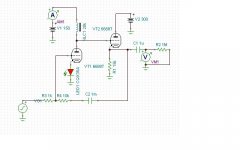
Everyone likes pictures so here's a circuit I tested in Tina. S/N is some 126dB and gain is about 18dB. These things really shine when the gain is really high.
Everyone likes pictures so here's a circuit I tested in Tina. S/N is some 126dB and gain is about 18dB. These things really shine when the gain is really high.
Attachments
Last edited:
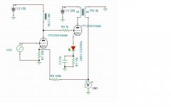
This one has a gain of some 55 dB, THD of 0.02% and S/N of 135 dB. I'm just scratching my head at these numbers because they are remarkable. How difficult is it to design the choke and transformer for something like this? Tube DC current is around 11 mA each. Xfr has a turns ratio of 4:1 step down.
Attachments
I am curious about plate load chokes. I have been studying them a little bit but I would like to understand more.
I would opt for cascoded CSS (with up to 160dB PSRR rate) instead of massive and expensive plate choke. Additionally, plate choke will have quite high stray capacitance no matter what.
I am curious about plate load chokes...
This is only certain below the resonant frequency of the choque. Self plus external capacitances (really or virtual, like the Miller one) resonates with the choke inductance at a frequency, above which the inductive reactance becomes capacitive, then causing several loss of gain increasing frequency. The problem is the same as with transformers, except it hasn't pri' to sec capacitance.
I would opt for cascoded CSS (with up to 160dB PSRR rate) instead of massive and expensive plate choke. Additionally, plate choke will have quite high stray capacitance no matter what.
Well, first off, I'm not really interested in being told that this is a bad idea yet again by people who a) too lazy to try it or even simulated it, and b) are too close minded to even investigate the possibility that there might be something out there that's cooler and maybe better.
Second, making a cascoded CCS that is professional and nice is just as expensive as buying two plate chokes. The cost of professionally made circuit boards is over $100. The parts add about $25 including shipping. The price of two chokes is about $120. So, maybe you should know what you're talking about before just blathering off?
This is only certain below the resonant frequency of the choque. Self plus external capacitances (really or virtual, like the Miller one) resonates with the choke inductance at a frequency, above which the inductive reactance becomes capacitive, then causing several loss of gain increasing frequency. The problem is the same as with transformers, except it hasn't pri' to sec capacitance.
OK, great, thank you. So the goal is to make the resonant frequency (stray capacitance + inductance) outside of the audio range? How do you do that?
Also, based on your comments, it appears that it would be best to use a tube that has a low Miller capacitance, like the VHF frame grid pentodes D3A, etc? I already understand that this technique is only good for tubes that operate at relatively high DC current and have low Rp, like the D3A, etc. So, no 12AX7, etc. is suitable for this technique. Would you agree with that?
Further, so would you agree with the idea that the back emf from the choke makes the plate load so high that the load becomes the next stage in the amplifier (below the resonant frequency of the choke/tube combination of course)? If that's the case, then I think it seems obvious that to maximize the back emf you have to maximize the inductance of the choke. What other parameters for the choke are important in maximizing back emf?
Last edited:
- Status
- Not open for further replies.
- Home
- Amplifiers
- Tubes / Valves
- Design of transformers for valve amplifiers