Well, this is my core...does it help ?If your core is good, we can do
Uac = √(P Zp) = √(10 x 3000) ≈ 173 VRMS
S = 2.86 x 4.3 x 0.9 ≈ 11 cm²
l ≈ 17.2 cm
Supposing now Bac=8000 Gauss, Bdc=6500 Gauss
Np = (Uac x 10⁸) / [√2 π fo S Bac(max)] ≈ 2212
Ns = Np √(η Zs / Zp) ≈ 108
Bdc(max) = [4 π μ Np i(DC)] / (9 l)
We have i(DC) = 80 mA, so
μeff ≈ 452
Lp = (8000/6500) (4 π μ S Np²) / (9 l x 10⁸) ≈ 24 H
Patience please...")
Attachments

Well, this is my core...does it help ?
Your core seems excellent, I think to have an almost win-win design, only copper loss a little bit high, but don't count our chickens before they hatch...
Hi Ives,that's why I've wrote some code !
Is the version 3.3.3 release is public?
I only have 3.3.3 beta (2010.04.20 V 3.3.0.3).
The latest published version (AFAIR the same you already have) is here:Hi Ives,
Is the version 3.3.3 release is public?
I only have 3.3.3 beta (2010.04.20 V 3.3.0.3).
http://www.dissident-audio.com/OPT_da/PST-and-OPT.tar.gz
It comes as an archive including all necessary files as long as DLL and other Win's stuff so that it doesn't need to be "installed", just extract the archive in a new folder. No more.
Neither your "System Path" nor the registry will be affected.
This also makes it simpler to run it with Wine under Linux:
Open the folder then launch OPT_da.exe from this folder.
As a bonus there is a power supply transformer calculator included: PST.exe
Forgotten to remove "beta" mention, sorry . . .
I'm still trying to improve. A 3.3.4 version may be available before . . heu . . Xmas ?
Yves.
Last edited:
Here is the complete calculation, counting on performance of your core
Uac = √(P Zp) = √(10 x 3000) ≈ 173 VRMS
For your core, stacking factor is 0.95, so
S = 2.86 x 4.3 x 0.95 ≈ 11.7 cm²
l ≈ 17.2 cm
Supposing now Bac=8000 Gauss, Bdc=6500 Gauss
Np = (Uac x 10⁸) / [√2 π fo S Bac(max)] ≈ 2080
Ns = Np √(η Zs / Zp) ≈ 102
Bdc(max) = [4 π μ Np i(DC)] / (9 l)
We have i(DC) = 80 mA, so
μeff ≈ 481
Lp = (8000/6500) (4 π μ S Np²) / (9 l x 10⁸) ≈ 24 H
Mean turn length, with correction for rounded corners is about
lm ≈ 188 mm
Then, for Φp=0.25mm Φs=1.05mm
Rp = ρ Np lm / (π rp²) ≈ 135 Ω
Rs = ρ Ns lm / (π rs²) ≈ 0.38 Ω
So
Ploss [%] = 100xRp/(Zp+Rp) ≈ 4.3 %
Sloss [%] = 100xRs/(Zs+Rs) ≈ 4.5 %
Not bad after all
Insertion Loss ≈ 0.4 dB
Suggested winding pattern
8P-3S-8P
S = 34 turns
P = 130 turns
With 0.1mm (polyester) between primary layrers, 0.05mm (polyester) between secondary layers, and 0.32mm (NOMEX) between each primary and secondary windings, and another 0.32mm to finish the bobbin
16x0.30+3x1.10+14x0.15+2x0.05+3x0.32 = 11.26mm
You have about 12mm, so you must wind to 94% window, is feasible.
Leakage inductance
Ls = [0.417 Np² lm (2 n c + a)] / (10⁹ n² b) ≈ 2.78 mH
Interwinding capacitance
C ≈ (ε A) / (4πd) ≈ 291 cm ≈ 324 pF
Interlayer capacitance
Cl ≈ (ε A) / (4πd) ≈ 1322 cm ≈ 1472 pF
Total winding capacitance
(Cw)⁻¹ ≈ (Cl)⁻¹ ∑ {(4/3nı) [1 - (1/nı)]}⁻¹ ı=1,...,NP
Cw ≈ 107 pF
Total distributed capacitance
Cd ≈ C ∑ (nı/N)² ı=1,...,m
Cd ≈ 162 pF
So shunt capacitance is
Cs = Cw + Cd ≈ 269 pF
Meets all the requirements, it is not an easy winding, but it is feasible.
Edit: I can't find μ in datasheet, so you must adjust air gap empiricaly to obtain desired Lp @ 20 Hz
Edit1: You can estimate air gap supposing μ≈47000, then
lG = l (μ - μeff) / (μ μeff) ≈ 0.35 mm
Last edited:
Bravo!!!!
Here is the complete calculation, counting on performance of your core
Uac = √(P Zp) = √(10 x 3000) ≈ 173 VRMS
For your core, stacking factor is 0.95, so
S = 2.86 x 4.3 x 0.95 ≈ 11.7 cm²
l ≈ 17.2 cm
Supposing now Bac=8000 Gauss, Bdc=6500 Gauss
Np = (Uac x 10⁸) / [√2 π fo S Bac(max)] ≈ 2080
Ns = Np √(η Zs / Zp) ≈ 102
Bdc(max) = [4 π μ Np i(DC)] / (9 l)
We have i(DC) = 80 mA, so
μeff ≈ 481
Lp = (8000/6500) (4 π μ S Np²) / (9 l x 10⁸) ≈ 24 H
Mean turn length, with correction for rounded corners is about
lm ≈ 188 mm
Then, for Φp=0.25mm Φs=1.05mm
Rp = ρ Np lm / (π rp²) ≈ 135 Ω
Rs = ρ Ns lm / (π rs²) ≈ 0.38 Ω
So
Ploss [%] = 100xRp/(Zp+Rp) ≈ 4.3 %
Sloss [%] = 100xRs/(Zs+Rs) ≈ 4.5 %
Not bad after all
Insertion Loss ≈ 0.4 dB
Suggested winding pattern
8P-3S-8P
S = 34 turns
P = 130 turns
With 0.1mm (polyester) between primary layrers, 0.05mm (polyester) between secondary layers, and 0.32mm (NOMEX) between each primary and secondary windings, and another 0.32mm to finish the bobbin
16x0.30+3x1.10+14x0.15+2x0.05+3x0.32 = 11.26mm
You have about 12mm, so you must wind to 94% window, is feasible.
Leakage inductance
Ls = [0.417 Np² lm (2 n c + a)] / (10⁹ n² b) ≈ 2.78 mH
Interwinding capacitance
C ≈ (ε A) / (4πd) ≈ 291 cm ≈ 324 pF
Interlayer capacitance
Cl ≈ (ε A) / (4πd) ≈ 1322 cm ≈ 1472 pF
Total winding capacitance
(Cw)⁻¹ ≈ (Cl)⁻¹ ∑ {(4/3nı) [1 - (1/nı)]}⁻¹ ı=1,...,NP
Cw ≈ 107 pF
Total distributed capacitance
Cd ≈ C ∑ (nı/N)² ı=1,...,m
Cd ≈ 162 pF
So shunt capacitance is
Cs = Cw + Cd ≈ 269 pF
Meets all the requirements, it is not an easy winding, but it is feasible.
Bravo!!!!
Gracias ! Pero no es para tanto, es solo una cuentita...
Thanks! But is only a little bit calculation...
Ls = [0.417 Np² lm (2 n c + a)] / (10⁹ n² b) ≈ 2.78 mH
Erratum
Ls = [0.417 Np² lm (2 n c + a)] / (10⁹ n² b) ≈ 27 mH
Sorry, but what is an order of magnitude between friends?
Another try with less leakage inductance
Uac = √(P Zp) = √(10 x 3000) ≈ 173 VRMS
For your core, stacking factor is 0.95, so
S = 2.86 x 4.3 x 0.95 ≈ 11.7 cm²
l ≈ 17.2 cm
Supposing now Bac=8000 Gauss, Bdc=6500 Gauss
Np = (Uac x 10⁸) / [√2 π fo S Bac(max)] ≈ 2080
Ns = Np √(η Zs / Zp) ≈ 102
Bdc(max) = [4 π μ Np i(DC)] / (9 l)
We have i(DC) = 80 mA, so
μeff ≈ 481
Lp = (8000/6500) (4 π μ S Np²) / (9 l x 10⁸) ≈ 24 H
Supposing μ≈47000 we can estimate the air gap
lG = l (μ - μeff) / (μ μeff) ≈ 0.35 mm
Mean turn length, with correction for rounded corners is about
lm ≈ 188 mm
Then, for Φp=0.25mm Φs=1.05mm
Rp = ρ Np lm / (π rp²) ≈ 135 Ω
Rs = ρ Ns lm / (π rs²) ≈ 0.38 Ω
So
Ploss [%] = 100xRp/(Zp+Rp) ≈ 4.3 %
Sloss [%] = 100xRs/(Zs+Rs) ≈ 4.5 %
Insertion Loss ≈ 0.4 dB
Suggested winding pattern (two primaries and three series secondaries)
S-8P-S-8P-S
S = 34 turns
P = 130 turns
With 0.05mm (NOMEX) between primary layrers, 0.4mm (five layers 0.08mm NOMEX) between each primary and secondary windings, and another 0.4mm to finish the bobbin
16x0.30+3x1.10+14x0.05+5x0.4 = 10.8mm
You have about 12mm, so you must winding to 90% window, easy.
Leakage inductance
Ls = [0.417 Np² lm (2 n c + a)] / (10⁹ n² b) ≈ 7.4 mH
Interwinding capacitance
C ≈ (ε A) / (4πd) ≈ 233 cm ≈ 259 pF
Interlayer capacitance
Cl ≈ (ε A) / (4πd) ≈ 1459 cm ≈ 1623 pF
Total winding capacitance
(Cw)⁻¹ ≈ (Cl)⁻¹ ∑ {(4/3nı) [1 - (1/nı)]}⁻¹ ı=1,...,NP
Cw ≈ 118 pF
Total distributed capacitance
Cd ≈ C ∑ (nı/N)² ı=1,...,m
Cd ≈ 373 pF
So shunt capacitance is
Cs = Cw + Cd ≈ 491 pF
Meets all the requirements, easy winding and a more equilibrated transformer.
Fortunately calculations give good results, other way I would cheat, like Ives did, making Zs=6 Ω Sacrebleu, c'est d'la triche!
Do you see? Better late than never.
Uac = √(P Zp) = √(10 x 3000) ≈ 173 VRMS
For your core, stacking factor is 0.95, so
S = 2.86 x 4.3 x 0.95 ≈ 11.7 cm²
l ≈ 17.2 cm
Supposing now Bac=8000 Gauss, Bdc=6500 Gauss
Np = (Uac x 10⁸) / [√2 π fo S Bac(max)] ≈ 2080
Ns = Np √(η Zs / Zp) ≈ 102
Bdc(max) = [4 π μ Np i(DC)] / (9 l)
We have i(DC) = 80 mA, so
μeff ≈ 481
Lp = (8000/6500) (4 π μ S Np²) / (9 l x 10⁸) ≈ 24 H
Supposing μ≈47000 we can estimate the air gap
lG = l (μ - μeff) / (μ μeff) ≈ 0.35 mm
Mean turn length, with correction for rounded corners is about
lm ≈ 188 mm
Then, for Φp=0.25mm Φs=1.05mm
Rp = ρ Np lm / (π rp²) ≈ 135 Ω
Rs = ρ Ns lm / (π rs²) ≈ 0.38 Ω
So
Ploss [%] = 100xRp/(Zp+Rp) ≈ 4.3 %
Sloss [%] = 100xRs/(Zs+Rs) ≈ 4.5 %
Insertion Loss ≈ 0.4 dB
Suggested winding pattern (two primaries and three series secondaries)
S-8P-S-8P-S
S = 34 turns
P = 130 turns
With 0.05mm (NOMEX) between primary layrers, 0.4mm (five layers 0.08mm NOMEX) between each primary and secondary windings, and another 0.4mm to finish the bobbin
16x0.30+3x1.10+14x0.05+5x0.4 = 10.8mm
You have about 12mm, so you must winding to 90% window, easy.
Leakage inductance
Ls = [0.417 Np² lm (2 n c + a)] / (10⁹ n² b) ≈ 7.4 mH
Interwinding capacitance
C ≈ (ε A) / (4πd) ≈ 233 cm ≈ 259 pF
Interlayer capacitance
Cl ≈ (ε A) / (4πd) ≈ 1459 cm ≈ 1623 pF
Total winding capacitance
(Cw)⁻¹ ≈ (Cl)⁻¹ ∑ {(4/3nı) [1 - (1/nı)]}⁻¹ ı=1,...,NP
Cw ≈ 118 pF
Total distributed capacitance
Cd ≈ C ∑ (nı/N)² ı=1,...,m
Cd ≈ 373 pF
So shunt capacitance is
Cs = Cw + Cd ≈ 491 pF
Meets all the requirements, easy winding and a more equilibrated transformer.
Fortunately calculations give good results, other way I would cheat, like Ives did, making Zs=6 Ω
Sacrebleu, c'est d'la triche! Do you see? Better late than never.
Last edited:
Hi Poppilin,
newbie question, how do you decide on how big your tube power traffo is going to be? how about output transformer?
Hi Tony
Difficult question, core sectional area would be unbelievably small for a given power to transfer from P to S, regardless if PT or OPT, but for practical reasons, basicaly the wire must fit in the window, there are a lot rules of thumb, however I rarely use them because in most cases I must work with a particular core and I have no choice...third world delights...
Regarding on THD, the smaller the better, core loss is related with magnetic hysteresis curve, as being not a straight line implies nonlinearity.
But there is a limit imposed by copper loss, the right balance is more an art than a science, and obviously I'm not an artist.
Last edited:
Unfortunately i have no EI material at home other wise i could try your design and post the results here. But i do have and old sm85B c-core 0,1mm
I did some calculations myself and although there are some differences they are not very big. I guess the the permeability won't be so high for EI materials but anyway the calculation are made with a permeability of ~470 so it doesn't matter.
I did some calculations myself and although there are some differences they are not very big. I guess the the permeability won't be so high for EI materials but anyway the calculation are made with a permeability of ~470 so it doesn't matter.
Another try with less leakage inductance
Uac = √(P Zp) = √(10 x 3000) ≈ 173 VRMS
For your core, stacking factor is 0.95, so
S = 2.86 x 4.3 x 0.95 ≈ 11.7 cm²
l ≈ 17.2 cm
Supposing now Bac=8000 Gauss, Bdc=6500 Gauss
Np = (Uac x 10⁸) / [√2 π fo S Bac(max)] ≈ 2080
Ns = Np √(η Zs / Zp) ≈ 102
Bdc(max) = [4 π μ Np i(DC)] / (9 l)
We have i(DC) = 80 mA, so
μeff ≈ 481
Lp = (8000/6500) (4 π μ S Np²) / (9 l x 10⁸) ≈ 24 H
Supposing μ≈47000 we can estimate the air gap
lG = l (μ - μeff) / (μ μeff) ≈ 0.35 mm
Mean turn length, with correction for rounded corners is about
lm ≈ 188 mm
Then, for Φp=0.25mm Φs=1.05mm
Rp = ρ Np lm / (π rp²) ≈ 135 Ω
Rs = ρ Ns lm / (π rs²) ≈ 0.38 Ω
So
Ploss [%] = 100xRp/(Zp+Rp) ≈ 4.3 %
Sloss [%] = 100xRs/(Zs+Rs) ≈ 4.5 %
Insertion Loss ≈ 0.4 dB
Suggested winding pattern (two primaries and three series secondaries)
S-8P-S-8P-S
S = 34 turns
P = 130 turns
With 0.05mm (NOMEX) between primary layrers, 0.4mm (five layers 0.08mm NOMEX) between each primary and secondary windings, and another 0.4mm to finish the bobbin
16x0.30+3x1.10+14x0.05+5x0.4 = 10.8mm
You have about 12mm, so you must winding to 90% window, easy.
Leakage inductance
Ls = [0.417 Np² lm (2 n c + a)] / (10⁹ n² b) ≈ 7.4 mH
Interwinding capacitance
C ≈ (ε A) / (4πd) ≈ 233 cm ≈ 259 pF
Interlayer capacitance
Cl ≈ (ε A) / (4πd) ≈ 1459 cm ≈ 1623 pF
Total winding capacitance
(Cw)⁻¹ ≈ (Cl)⁻¹ ∑ {(4/3nı) [1 - (1/nı)]}⁻¹ ı=1,...,NP
Cw ≈ 118 pF
Total distributed capacitance
Cd ≈ C ∑ (nı/N)² ı=1,...,m
Cd ≈ 373 pF
So shunt capacitance is
Cs = Cw + Cd ≈ 491 pF
Meets all the requirements, easy winding and a more equilibrated transformer.
Fortunately calculations give good results, other way I would cheat, like Ives did, making Zs=6 Ω
Do you see? Better late than never.
Unfortunately i have no EI material at home other wise i could try your design and post the results here. But i do have and old sm85B c-core 0,1mm
That would be great, an experimental check.
I did some calculations myself and although there are some differences they are not very big. I guess the the permeability won't be so high for EI materials but anyway the calculation are made with a permeability of ~470 so it doesn't matter.
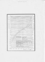
Calculations I did with μeff ≈ 481, however in datasheet there is not μ, then I took that value from Edcor M6 lamination μ ≈ 47000 @ 16000 Gauss (DC) only to estimate the air gap.
https://www.edcorusa.com/t/Mtr-Core-Steel
μeff = [Bdc(max) 9 l] / [4 π Np i(DC)]
Last edited:
Reading almost all the thread, I get an important conclusion: a deep headache!
Recently I designed a .3Hy inductor in EC34 cores for a rare special project, and two things are now clear for me:
1) winding technique is very important. Changing from U to Z winding DO reduces the capacitance, or almost reduces notably the effects on the finished work,
2)Using teflon tape as for piping, between layers of coil, still further reduces the interwinding capacitance (Popilin suggestion).
Using both technologies in a hand wired inductor, I had a reduction in 3 to 5 times the capacitance. I follow some Popilin concepts, and the concepts in http://download.21dianyuan.com/download.php?id=82186 in respecto U and z windings.
Next time I re-try using a core with higher Al, and partitioned coil former.
Reading almost all the thread, I get an important conclusion: a deep headache!
Hi my friend, good to see you around here.
Well, words are not my thing, I only can explain things with equations, and now I realize that I did a mess with μ and μeff, not a mistake but is difficult to understand, especially for whom see those equations for first time, but I promise I will fix it.
Recently I designed a .3Hy inductor in EC34 cores for a rare special project, and two things are now clear for me:
1) winding technique is very important. Changing from U to Z winding DO reduces the capacitance, or almost reduces notably the effects on the finished work,
2)Using teflon tape as for piping, between layers of coil, still further reduces the interwinding capacitance (Popilin suggestion).
Using both technologies in a hand wired inductor, I had a reduction in 3 to 5 times the capacitance. I follow some Popilin concepts, and the concepts in http://download.21dianyuan.com/download.php?id=82186 in respecto U and z windings.
Glad to know that my elucubrations are useful to someone.
Next time I re-try using a core with higher Al, and partitioned coil former.
That's a great idea, vertical sectioning really works, and soon an explanation, the bad news is...more equations...
el156, could you post the sheet with the table for items 1 - 15?
tks
steven
Hi Steven ! No, i dont have the table for items 1-15, but i will try to get it if it is available from the core suplier . If i can get it, i will post it here .
Silvino
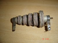
That's a great idea, vertical sectioning really works, and soon an explanation, the bad news is...more equations...
Yes, but in the next time I'll also use horizontal partitioning, say, like the RF choke in the photo.
Attachments
- Status
- Not open for further replies.
- Home
- Amplifiers
- Tubes / Valves
- Design of transformers for valve amplifiers