Tip#5 Wet or Dry
Some people prefers dry transformers, I mean without any varnish bath, air is the best insulator...when dry, humid air has about 900V breakdown, so I prefer varnish, but even with a vacuum chamber, varnish do not enter totaly inside the windings, but not all is lost, epoxy is the solution, bad news is that you must build wet windings, after finish a winding, you put wood pieces with 0.05 mm mylar, because epoxy pours, and press to the nominal winding high for about three days and it works very well.
You can use Aquapon 97 series epoxy, by PPG, pot life between 12 to 24 hours.
Is a little insane invest three days for each winding, but the result is amazing, and windings are more safe from HV effects and can't sing.
Hi popilin,
Here is a poor man measuring jig:

Apologies for French, but IIRW, someone from this forum translated that.
I'll try to find who did . . .
By the way, according to my own experience, beware that EACH primary section is prone to resonate because of its parasitic capacitance and this is the only reason to add "something" between successive layers.
At high frequency remember that the excitation (induction) of the core is very very low and that the inductance of each section is much lower that one beleive because the Mu fall drastically.
You may easily check that by plotting frequency response with and without iron and see that there is almost no difference above, say, 5Khz.
Have fun.
Yves.
Here is a poor man measuring jig:
Apologies for French, but IIRW, someone from this forum translated that.
I'll try to find who did . . .
By the way, according to my own experience, beware that EACH primary section is prone to resonate because of its parasitic capacitance and this is the only reason to add "something" between successive layers.
At high frequency remember that the excitation (induction) of the core is very very low and that the inductance of each section is much lower that one beleive because the Mu fall drastically.
You may easily check that by plotting frequency response with and without iron and see that there is almost no difference above, say, 5Khz.
Have fun.
Yves.
Hi popilin,
Here is a poor man measuring jig:
Apologies for French, but IIRW, someone from this forum translated that.
I'll try to find who did . . .
Monsieur Ives Monmagnon, un autre légende des transformateurs, je suis honoré de votre visite, merci beaucoup !
")
I use to use the first circuit, but without the variac "poorest man version"
By the way, according to my own experience, beware that EACH primary section is prone to resonate because of its parasitic capacitance and this is the only reason to add "something" between successive layers.
Before I put insulation between layers only as a formality (pour la forme), a while ago, while doing the derivation of equations, I realized that is so important.
But more important is your experience in that respect, thanks.
At high frequency remember that the excitation (induction) of the core is very very low and that the inductance of each section is much lower that one beleive because the Mu fall drastically.
You may easily check that by plotting frequency response with and without iron and see that there is almost no difference above, say, 5Khz.
Have fun.
Yves.
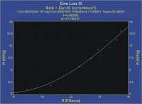
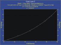
I agree, from eq (23) is perfectly clear that at high frequencies, B tends to cancel, and above certain frequency is as if there were not core at all, bad news is for my cores that frequency is much smaller...third world delights...
À bientôt
Tip#4 Interwinding insulation
We must be very cautious here, because voltages involved can be very high, mostly in OPT when secondaries are grounded.
The best of the best insulator is NOMEX, you can kill three birds with one stone
1- Insulation, about 27 KV/mm for 0.08mm NOMEX 410
2- Low dielectric constant, about 1.6 for 0.08mm NOMEX 410
3- Heat resistant
Five to seven layers of 0.08mm would be enough for most cases.
Tengo una duda:
If the enameled wire has a breakdown voltage of 4kV, wouldn´t 0.1mm of interwinding insulation be more than enough? This would also reduce leakage inductance (although it would also increase capacitance but this is less critical)
Suppose a SE transformer rated at 10W (8 ohm) for tubes with a plate voltage of 300V. Step down ratio 22. The peak voltage between primary and secondary will be 500V. With 0.1mm nomex the total breakdown voltage will be 31kV or 62 times the peak voltage! (Talk about safety factor!)
Tengo una duda:
If the enameled wire has a breakdown voltage of 4kV, wouldn´t 0.1mm of interwinding insulation be more than enough? This would also reduce leakage inductance (although it would also increase capacitance but this is less critical)
Well, no, things are a bit more complicated than that, and capacitance is the most difficult parameter to maintain under control, and the most critical too.IMHO
Suppose a SE transformer rated at 10W (8 ohm) for tubes with a plate voltage of 300V. Step down ratio 22. The peak voltage between primary and secondary will be 500V. With 0.1mm nomex the total breakdown voltage will be 31kV or 62 times the peak voltage! (Talk about safety factor!)
Breakdown voltage would be
Vb = 3 (Upp+Udc) = 3(530V+300V) = 2490V
With 0.1mm NOMEX will be a voltage breakdown of about 1700V, is not enough, even if the windings were infinite, but they are not, at its extremes electric field E has a maximum and there the breakdown distance is reduced unless you let a safety margin between winding and coil former, anyway you must increase insulation.
Do not put the hands on the fire with wire enamel, 4KV is specified for a straight wire, on the corners it will reduce, and you must consider eight critical points at the interphases.
A good compromise is 0.4mm NOMEX, it works very well for both insulation and capacitance, leakage inductance must be reduced by interleaving.
NOMEX datasheet looks a bit confusing because specified 17KV/mm for 0.05mm, 22KV/mm for 0.08mm, 27KV/mm for 0.13mm (sorry, was a typo there),...
If wire+insulation doesn't fit into the window, you can sacrify copper losses (thinner wire) or bass response (less turns), or winding with another technique, with epoxy I can winding to about 95% (or more) of window, but requires a lot of time and patience.
Last edited:
Another reason to wind ones own transformers is to replace transformers that are damaged.
I have a Magnavox 196 chassis with one transformer bad. I could replace both, but prefer to rewind the bad one instead.
I tried tissue paper on my first (and only) transformer and found it tears too easily. I switched to bamboo paper (Model Airplane covering) and prefer it for its strength.
I also have Mylar and Kapton tape, but the dielectric constant is much higher for those.
For small transformers, craft paper is too stiff.
Another reason to wind ones own transformers is to replace transformers that are damaged.
I have a Magnavox 196 chassis with one transformer bad. I could replace both, but prefer to rewind the bad one instead.
I tried tissue paper on my first (and only) transformer and found it tears too easily. I switched to bamboo paper (Model Airplane covering) and prefer it for its strength.
I also have Mylar and Kapton tape, but the dielectric constant is much higher for those.
For small transformers, craft paper is too stiff.
Rewind old transformers is a PITA, beginning with old lamination, unwinding, respect the original insulators...you must have more experience and skills than me.
Between layers I use 0.05mm polyester because it is soft and cheap, here is used for roof cover, I had problems with paper, as I use epoxy, paper tends to break and is difficult to impregnate.
Hi, I do not consider myself as a specialist in transformers, but if you can put more info, maybe for tomorrow I can post a complete design as an example of how equations work.
I need: Primary impedance, power, primary DC current, lowest frequency and more details about core and coil former (geometry)
Ok...primary impedance should be 3K
Power 10 Watts
Dc current max 80 Ma
The core is M6 steel
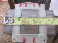
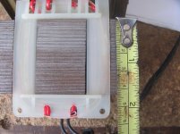
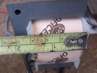
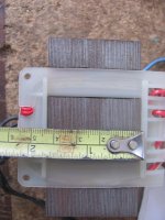
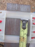
The size is as i show in the pictures
Lowest frequency 20 Hz
Now...is it possible to make a transformer with this material?
Thanks
Attachments
Ok...primary impedance should be 3K
Power 10 Watts
Dc current max 80 Ma
The core is M6 steel
The size is as i show in the pictures
Lowest frequency 20 Hz
Now...is it possible to make a transformer with this material?
Thanks
Almost always it can be done, however your core is a bit small, surely will have a couple of compromises, give me time, I hope by tomorrow I will have all calculations.
No, I have little experience (Which may be why I will try to rewind the Magnavox transformer). This is not a high quality transformer like Harmon Karden or HH Scott, etc. It is a simple SE output transformer for an EL84.
Come on, I had seen your handmade winding machine, it talks for itself.
With that skills, surely you will make an excellent transformer, I bet you will rewind both, because the new will sound better than the other.
Definitely NO !. . .
Now...is it possible to make a transformer with this material?
Thanks
Unless you accept to reduce your ambitions . . .
If you accept to limit the lowest frequency at 30Hz for full power (10W), it becomes feasible and will produce more than decent results at high end.
You'll still be able to obtain some 4.5 W "clean" at 20Hz.
In other words, it will be a 10W OPT able to go down to 20Hz but not both simultaneously
Yves.
Sorry popilin, my computer is faster than your brain
But we agree !
Attachments
Definitely NO !
Sorry popilin, my computer is faster than your brain
Touché
My brain works too slowly...
But give me more time, I think that I have a rabbit in the galley...a slow one...
Last edited:
Indeed, I'm too lazy to make that "manually", that's why I've wrote some code !
Old programer joke:
Give one hour to a programer to solve a problem and he will spend 59 minutes writing the code that find the solution in one minute
Indeed, I've spend more than a year . . .
Yves.
Old programer joke:
Give one hour to a programer to solve a problem and he will spend 59 minutes writing the code that find the solution in one minute
Indeed, I've spend more than a year . . .
Yves.
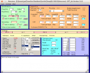
Is this the program you use Yves?
( i can check it now because i have an Imac computer)
OPT Calucator
( i can check it now because i have an Imac computer)
OPT Calucator
So Yvesm, your computer says that i need to wind 1480 turns of 0,35 mm wire for my transformer? well, i will wait for popilin slow calculations !!!Definitely NO !
Unless you accept to reduce your ambitions . . .
If you accept to limit the lowest frequency at 30Hz for full power (10W), it becomes feasible and will produce more than decent results at high end.
You'll still be able to obtain some 4.5 W "clean" at 20Hz.
In other words, it will be a 10W OPT able to go down to 20Hz but not both simultaneously
Yves.
Sorry popilin, my computer is faster than your brain
But we agree !
Uac = √(P Zp) = √(10 x 3000) ≈ 173 VRMS
S = 2.86 x 4.3 x 0.9 ≈ 11 cm²
l ≈ 17.2 cm
Supposing Bac=Bdc=6500 Gauss
Np = (Uac x 10⁸) / [√2 π fo S Bac(max)] ≈ 2722
Ns = Np √(η Zs / Zp) ≈ 133
Bdc(max) = [4 π μ Np i(DC)] / (9 l)
We have i(DC) = 80 mA, so
μeff ≈ 368
Lp = (4 π μ S Np²) / (9 l x 10⁸) ≈ 24 H
lG = l (μ - μeff) / (μ μeff) Depends on your lamination
Is possible, only need to find wire diameters that fits in the bobbin, so copper losses is the only parameter to resign.
Just give me more time to find a winding pattern too.
Last edited:
OK ! Thank you popilin !!!Uac = √(P Zp) = √(10 x 3000) ≈ 173 VRMS
S = 2.86 x 4.3 x 0.9 ≈ 11 cm²
l ≈ 17.2 cm
Supposing Bac=Bdc=6500 Gauss
Np = (Uac x 10⁸) / [√2 π fo S Bac(max)] ≈ 2764
Ns = Np √(η Zs / Zp) ≈ 135
Bdc(max) = [4 π μ Np i(DC)] / (9 l)
We have i(DC) = 80 mA, so
μeff ≈ 362
Lp = (4 π μ S Np²) / (9 l x 10⁸) ≈ 24 H
lG = l (μ - μeff) / (μ μeff) Depends on your lamination
Is possible, only need to find wire diameters that fits in the bobbin, so copper losses is the only parameter to resign.
Just give me more time to find a winding pattern too.
If your core is good, we can do
Uac = √(P Zp) = √(10 x 3000) ≈ 173 VRMS
S = 2.86 x 4.3 x 0.9 ≈ 11 cm²
l ≈ 17.2 cm
Supposing now Bac=8000 Gauss, Bdc=6500 Gauss
Np = (Uac x 10⁸) / [√2 π fo S Bac(max)] ≈ 2212
Ns = Np √(η Zs / Zp) ≈ 108
Bdc(max) = [4 π μ Np i(DC)] / (9 l)
We have i(DC) = 80 mA, so
μeff ≈ 452
Lp = (8000/6500) (4 π μ S Np²) / (9 l x 10⁸) ≈ 24 H
Patience please...
- Status
- Not open for further replies.
- Home
- Amplifiers
- Tubes / Valves
- Design of transformers for valve amplifiers