There are some new materials available last 20 years, amorph and nano crystaline alloys.
I don't think that transformer technology has changed much, if at all, in the last seven decades.
All the materials and knowledge we have was probably available before WW2.
OK ! But i accept with this core 6 Watts and 30 Hz, is it possible with this core ? anyway, i will not get much more with EL34 triode conected, so 6 watt will be ok for me !
Thanks
Sorry I missed this one. Yes it is possible. IMHO it could better accepting a power loss of 0.5 dB. If you want I can send you my solution.
My numbers for permeability are REAL and MEASURED.
That mean you have winding the transformer of post#71? That's great! Your best contribution! Please post some measurements.
")
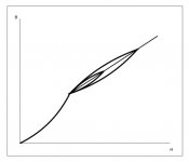
And permeability will never be constant.
Agree, so I did say "constant" rather than constant because magnetic anisotropy ever implies a hysteresis loop, although very thin it is a loop after all
With a careful design, you can make hysteresis loss very small, so the area of the curve B=f(H) will be also very small, as μ(AC) is the slope of the curve, it can be almost constant, that's the goal for linearity...it is very simple and now I reduced it to simple geometry, maybe you can understand it this way.
Its variation is only reduced with the gap and it not max at a generic Bmax. It depends on the material, the gap and where you are.
No, you are wrong, let me explain
Lamination has a μ, and in its datasheet there is μ=f(H), here μ reaches an absolute maximum.
In a PP OPT, air gap is negligible, so, if you work in the region of that absolute maximum, your transformer also does, and also can reaches that absolute maximum.
In a SE OPT things are a lot different, you have an air gap, and μ now is
μeff ≈ l μ / (l + lG μ)
Now you have a completely different μ=f(H) curve, because, as I said before, μ is reduced between one to two orders of magnitude, about two in this case.
Now is a little bit difficult to see a maximum, isn't it?
Due to we need a margin for Bdc, the rest of the curve is pretty constant, then doesn't matter which hysteresis loop you look at, always μ(AC) reaches a maximum at its corresponding Bac(max)
SE transformers works this way!!!
The goal is to get the best possible behaviour which means 2*pi*f*L >> Req.
Sorry to say that, but you are really confused, and I say for the second time, you confuse Push-Pull OPTs with Single-Ended OPTs.
On post#146 you put your "reference article", I don't know if you didn't read it, or you didn't understand it.
Here is a measurement:
http://plitron.com/wp-content/uploads/Atcl_3.pdf
On page 4, says:
sic It can easily be proven mathematically that below saturation, the voltage distortion will be small and nearly independent of the μr behavior, as long as the condition of formula 7 is met:
2 π f Lp >> Req (7)
After, on page 5, says:
sic However, it can become necessary to design transformers with small primary inductances.This is the case in single-ended types, where you must create a balance between DC and AC saturation, resulting in a much smaller Lp than in the push-pull situation. The condition of formula 7 will not be met, so it is absolutely necessary to provide a constant μr behavior to prevent the voltage distortion from becoming very large.
No words...
The other main point was that you got a completely wrong value for Bdc confusing dc values with ac values.
Can you please tell me where? Thanks.
Can you please tell me where? Thanks.
Post 71. You wrongly supposed 6500 gauss. With 2080 turns and 80 mA on that core Bdc is just over 4100.
Still you have to explain why the Tango has 20H at 1 mW and 26H nominal. I think you should stop going round in circles and be honest at least with yourself!
Bye bye
Sorry to say that, but you are really confused, and I say for the second time, you confuse Push-Pull OPTs with Single-Ended OPTs.
Again! You really sound like a broken record now. I SPECIFIED in that example it was a PP and there is a big variation in mu but this doesn't mean that it doesn't happen in SE. I think you should read carefully and think before posting. Everyone understood the concept but you! Anyway I posted the FC-30 specs.
Of course, as it looks like your mental flexibility and memory are very limited I am referring to standard M6 EI. That's what I measured. If one has better grades it will be better!! No bad surprises. After one could decide to re-make it but it will not be necessary. Instead if the design is too optimistic things won't be the same. Understand?
Then compute everything at 30Hz for 0.75-0.85T total B and see what you get at 20Hz. This way it is easier to optimize it. The main point is that it is pointless doing at 20Hz because even if the total induction at max RMS power will be 1-1.2T the inductance will not be such that 2*pi*f*L >> Req in most cases. So distortion will increase inevitably and quite substantially. There are only few cases, like the 300B and few others, where one can get a good ratio.
Going higher than 1-1.2T with EI at 20Hz is simply bad.
As I also told in other occasions one could also leave some room for peaks avoiding saturation tout-court. It makes a difference. Make some transformers first and at least one amp then.....practice makes a difference in addressing things!!!
Last edited:
Osvaldo,
I'm travelling to Buenos Aires in October. Let me know what valves you need and I can bring them with me
Cheers
Ale
Many thanks. I sent a PM to you!
Very generous.
Last edited:
That mean you have winding the transformer of post#71?
Can not see any of the images in this post...
How did you calculated this?
Post 71. You wrongly supposed 6500 gauss. With 2080 turns and 80 mA on that core Bdc is just over 4100.
Still you have to explain why the Tango has 20H at 1 mW and 26H nominal. I think you should stop going round in circles and be honest at least with yourself!
Bye bye
Can not see any of the images in this post...
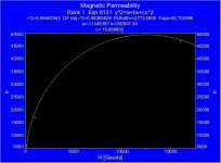
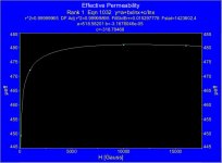
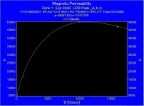
I swear I uploaded the images correctly, in the morning I asked to moderators to solve the problem, because I lost the whole Sunday making them, with data processing included.
Last edited:
Post 71. You wrongly supposed 6500 gauss. With 2080 turns and 80 mA on that core Bdc is just over 4100.
When you design a SE OPT, one of the first decisions is to choose the fields Bac(max) and Bdc(max)
For a so small core I chose
Bac(max) = 8000 Gauss Bdc(max) = 6500 Gauss
Because of the quality of the core, the total field
Bac(max)+Bdc(max) = 14500 Gauss = 1.45 T
Is below saturation, so that choosing was not ideal, but neither too bad, it is a design criteria, not a calculation.
Your design preconceptions would not be of universal application, you know?
But if you want a calculation, no problem
Bdc(max) = [4 π μ Np i(DC)] / (9 l)
For μeff ≈ 481, S ≈ 11.7 cm², Np = 2080, l ≈ 17.2 cm, i(DC) = 80 mA
Bdc(max) ≈ 6497 Gauss
Not just over 4100, isn't it?
Still you have to explain why the Tango has 20H at 1 mW and 26H nominal. I think you should stop going round in circles and be honest at least with yourself!
Bye bye
Are you kidding?
You already gave an answer, but because of your poor understanding about transformers, that merely reduces to copy and paste things and links that you neither understand, you didn't realized that.
Then as soon as Bac is 50-100 Gauss mu AC increases a lot and then it changes very little for quite a bit.
This is also wrong, because after a little initial increase, μ(AC) is quite constant out to saturation.
Because of this, for SE OPT, the gap will keep the working inductance to about 1.3 times the inductance of rest voltage.
Now you can stop with the nonsense of the maximum μ(AC), as I said before SE OPT works this way, no need for fanciful explanations.
Last edited:
Sorry I missed this one. Yes it is possible. IMHO it could better accepting a power loss of 0.5 dB. If you want I can send you my solution.
Ok 45 ! if you dont mind sending me your solution i will apreciate it !
Thank you
 Next person to get personal gets two weeks in Read Only mode.
Hi SY
Here the disappeared images of post #203, in order, I lost the whole Sunday making them with data processing included, if you can do something.
Thanks in advance.
Here the disappeared images of post #203, in order, I lost the whole Sunday making them with data processing included, if you can do something.
Thanks in advance.
Attachments
Which core? You used the Edcor datasheet to determine the permeability of another UNKNOWN core! ROTFL!!!When you design a SE OPT, one of the first decisions is to choose the fields Bac(max) and Bdc(max)
For a so small core I chose
Bac(max) = 8000 Gauss Bdc(max) = 6500 Gauss
Because of the quality of the core, the total field
Bac(max)+Bdc(max) = 14500 Gauss = 1.45 T
Is below saturation, so that choosing was not ideal, but neither too bad, it is a design criteria, not a calculation.
Your design preconceptions would not be of universal application, you know?
But if you want a calculation, no problem
Bdc(max) = [4 π μ Np i(DC)] / (9 l)
For μeff ≈ 481, S ≈ 11.7 cm², Np = 2080, l ≈ 17.2 cm, i(DC) = 80 mA
Bdc(max) ≈ 6497 Gauss
Then 481 and 6497 are really practical numbers!

Not just over 4100, isn't it?
Yes, for regular standard M6. That's the right way when something is unknown.
Designing is not dreaming!
Do you want to bet?Are you kidding?
No, everyone understood but you. Get over it!You already gave an answer, but because of your poor understanding about transformers, that merely reduces to copy and paste things and links that you neither understand, you didn't realized that.
Again! No, no and no!!!This is also wrong, because after a little initial increase, μ(AC) is quite constant out to saturation.
Now you can stop with the nonsense of the maximum μ(AC), as I said before SE OPT works this way, no need for fanciful explanations.
Re-shuffling equations is not enough.
Last edited:
Hi SY
Here the disappeared images of post #203, in order, I lost the whole Sunday making them with data processing included, if you can do something.
Thanks in advance.
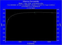
I am afraid that's not the real thing! At least make your calculation on a real curve.
Here the same graphs, but with correct field B instead of H, sorry, is the tradition to put H over x axis, and definitely for magnetic permeability, that function adjusts much better the few points.
By the way, the data here
https://www.edcorusa.com/t/Mtr-Core-Steel
Seems to be the only company that use cgs units.
Good for Edcor!
By the way, the data here
https://www.edcorusa.com/t/Mtr-Core-Steel
Seems to be the only company that use cgs units.
Good for Edcor!
Attachments
Last edited:
Sorry to say that...again
diyAudio has more than 300000 members, many come here to learn, including me, we are here to help each other, and I think is my duty to correct as many mistakes as I can with my limited knowledge, remember that I'm just a TV repairman.
Your continuous mistakes and misunderstandings can be detrimental and don't help us too much, is nothing personal against you, but for the good of this community.
Good and reliable information about transformers is very scarce, unless you land over Yvesm's page with his amazing software, or Patrick Turner's page with a lot of practical advice, so the idea was to post the correct equations and some useful data, transformer design is not a kind of black magic, if you want to do a deeper analysis that's fine, but do it right, with the right physical foundation.
That was on post#146, but since post#114 you have been writing nonsense about magnetic permeability, with that of the maximum μ(AC) for SE OPT, and amazingly you still insist on that!!!
No, honestly I don't understand the idea, my Tarzan-English is also very limited.
Can you see?
Almost all your analysis is based on a wrong supposition, i.e. the requisite that must be achieved the condition
2 π f Lp >> Req
As I said before, that is valid for Push-Pull OPTs and unattainable for properly designed SE OPTs, in addition, that's a dark concept, only for experts.
I'm not an expert, and I prefer simpler reasonings as is better to design a transformer for lowest possible frequency, because distortion reaches a maximum at Bac(max) due to magnetizing current also reaches its maximum, as it is a highly distorted current.
As a bonus, a transformer designed for 20Hz (more turns) will have lower distortion at 30Hz than the same transformer designed for 30Hz (less turns).
Easy! Even I can understand it.
And...what about copper losses? Does not have nothing to do with distortion?
Curiously you do always criticize the achilles heel of my designs cited as an example, on post#71 I did what I could, with a very small core, but of high quality, and I still thinking that is a reasonably good design, after all, an EL34 triode connected is not precisely a power house.
Not necessarily, there are a lot of better magnetic materials out there, and standard M6 GOSS is not the only one, Japanese standards are amazing, just to mention one.
That's I mean with design transformers for the lowest possible frequency.
I already made some transformers and some amplifiers, and some preamplifiers too, for customers happy with them.
Sometimes theory makes also a difference in addressing things!!!
diyAudio has more than 300000 members, many come here to learn, including me, we are here to help each other, and I think is my duty to correct as many mistakes as I can with my limited knowledge, remember that I'm just a TV repairman.
Your continuous mistakes and misunderstandings can be detrimental and don't help us too much, is nothing personal against you, but for the good of this community.
Good and reliable information about transformers is very scarce, unless you land over Yvesm's page with his amazing software, or Patrick Turner's page with a lot of practical advice, so the idea was to post the correct equations and some useful data, transformer design is not a kind of black magic, if you want to do a deeper analysis that's fine, but do it right, with the right physical foundation.
Again! You really sound like a broken record now. I SPECIFIED in that example it was a PP and there is a big variation in mu but this doesn't mean that it doesn't happen in SE. I think you should read carefully and think before posting. Everyone understood the concept but you!
That was on post#146, but since post#114 you have been writing nonsense about magnetic permeability, with that of the maximum μ(AC) for SE OPT, and amazingly you still insist on that!!!
Anyway I posted the FC-30 specs.
Of course, as it looks like your mental flexibility and memory are very limited I am referring to standard M6 EI. That's what I measured. If one has better grades it will be better!! No bad surprises. After one could decide to re-make it but it will not be necessary. Instead if the design is too optimistic things won't be the same. Understand?
No, honestly I don't understand the idea, my Tarzan-English is also very limited.
Then compute everything at 30Hz for 0.75-0.85T total B and see what you get at 20Hz. This way it is easier to optimize it. The main point is that it is pointless doing at 20Hz because even if the total induction at max RMS power will be 1-1.2T the inductance will not be such that 2*pi*f*L >> Req in most cases. So distortion will increase inevitably and quite substantially. There are only few cases, like the 300B and few others, where one can get a good ratio.
Can you see?
Almost all your analysis is based on a wrong supposition, i.e. the requisite that must be achieved the condition
2 π f Lp >> Req
As I said before, that is valid for Push-Pull OPTs and unattainable for properly designed SE OPTs, in addition, that's a dark concept, only for experts.
I'm not an expert, and I prefer simpler reasonings as is better to design a transformer for lowest possible frequency, because distortion reaches a maximum at Bac(max) due to magnetizing current also reaches its maximum, as it is a highly distorted current.
As a bonus, a transformer designed for 20Hz (more turns) will have lower distortion at 30Hz than the same transformer designed for 30Hz (less turns).
Easy! Even I can understand it.
And...what about copper losses? Does not have nothing to do with distortion?
Curiously you do always criticize the achilles heel of my designs cited as an example, on post#71 I did what I could, with a very small core, but of high quality, and I still thinking that is a reasonably good design, after all, an EL34 triode connected is not precisely a power house.
Going higher than 1-1.2T with EI at 20Hz is simply bad.
Not necessarily, there are a lot of better magnetic materials out there, and standard M6 GOSS is not the only one, Japanese standards are amazing, just to mention one.
As I also told in other occasions one could also leave some room for peaks avoiding saturation tout-court. It makes a difference.
That's I mean with design transformers for the lowest possible frequency.
Make some transformers first and at least one amp then.....practice makes a difference in addressing things!!!
I already made some transformers and some amplifiers, and some preamplifiers too, for customers happy with them.
Sometimes theory makes also a difference in addressing things!!!
I really don't care who you are and what you are!!! I don't want to help because you don't deserve it!Sorry to say that...again
diyAudio has more than 300000 members, many come here to learn, including me, we are here to help each other, and I think is my duty to correct as many mistakes as I can with my limited knowledge, remember that I'm just a TV repairman.
Which mistakes? WHERE ARE MODERATORS WHEN OTHER MEMBERS DISCREDIT???Your continuous mistakes and misunderstandings can be detrimental and don't help us too much, is nothing personal against you, but for the good of this community.
I on;y criticize mistakes. You are not using REAL numbers. The curves you show are not the real ones.That was on post#146, but since post#114 you have been writing nonsense about magnetic permeability, with that of the maximum μ(AC) for SE OPT, and amazingly you still insist on that!!!
Yes unfortunately!No, honestly I don't understand the idea, my Tarzan-English is also very limited.
NO you don't understand as you wrote yourself. The idea is MAXIMIZE Lp, MINIMIZE distorton.Almost all your analysis is based on a wrong supposition, i.e. the requisite that must be achieved the condition
2 π f Lp >> Req
The >> is considered valid if there is at least one order of magnitude.As I said before, that is valid for Push-Pull OPTs and unattainable for properly designed SE OPTs, in addition, that's a dark concept, only for experts.
The Tango FC30 is already achieving MORE THAN 8 at 30Hz. DO you want to bet it is possible to do even better?
I only criticize mistakes. You calculation is wrong with standard M6. EL156 won't (luckily) get that high Bdc and won't get 24H with 2080 turns and 0.35 mm gap. Do you want to bet?Curiously you do always criticize the achilles heel of my designs cited as an example, on post#71 I did what I could, with a very small core, but of high quality, and I still thinking that is a reasonably good design, after all, an EL34 triode connected is not precisely a power house.
We are not talking about other magnetics materials sorry! Are you trying to confuse people here????Not necessarily, there are a lot of better magnetic materials out there, and standard M6 GOSS is not the only one, Japanese standards are amazing, just to mention one.
Sometimes theory makes also a difference in addressing things!!!
Not in this case!
Last edited:
what's new?
It appears that the two of you have reached a deadlock again, surprise...
popilin - could you please just summarize what is new or different with your equations (if any) vis-a-vis the "old" equations. You have posted so much stuff, so a short summary statement would be very helpful.
It appears that the two of you have reached a deadlock again, surprise...
popilin - could you please just summarize what is new or different with your equations (if any) vis-a-vis the "old" equations. You have posted so much stuff, so a short summary statement would be very helpful.
- Status
- Not open for further replies.
- Home
- Amplifiers
- Tubes / Valves
- Design of transformers for valve amplifiers