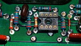
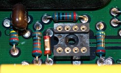
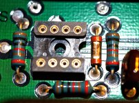
this unknown part is to see at second picture from post #2, main PCB left corner, in front of "PHONO AMP HIGH LEVEL" - module resp. left hand from DIP-8 socket.0.1 uf cap?
0.1 uf cap?
high resolution pictures in the attachement.
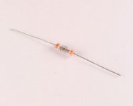
Yes, it is a chip SMD capacitor like
http://de.farnell.com/jsp/displayPr...ductlistings&gclid=CMa3xMm9srwCFYjLtAodB2AA6g
in a vitreous envelope, maybe for military and aerospace applications.
Who know the manufacturer?
Attachments
Last edited:
high resolution pictures in the attachement.
Yes, it is a chip SMD capacitor like
CC1206KRX7R9BB104 - YAGEO (PHYCOMP) - KONDENSATOR 100000PF 50V | Farnell Deutschland
in a vitreous envelope, maybe for military and aerospace applications.
Who know the manufacturer?
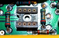
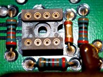
according
Unitrode UICC
and
Unitrode Distributor - 4 Star Electronics
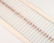
the Trademark "U" is Unitrode UICC
examples as offer
684 = 0,68µF
CGF684ZDZ UNITRODE 0.68uF 50V Ceramic Monolithic Axial capacitor 2020022399
560 = 56pF
CGB561JDN UNITRODE 560pF 50V Ceramic Monolithic Axial capacitor 2020022373
CGB560JDN UNITRODE 56pF 50V Ceramic Monolithic Axial capacitor 2020022370
who can upload a datasheet ?
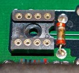
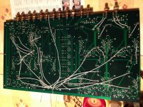
Last picture shows the PCB from solder site.
Attachments
Last edited:
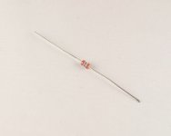
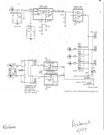
tiefbassuebertr. I simplified your schematic by white'ing-out the NU [not used] DC servo circuits; since they do not affect operation. An outstanding question maybe: What is the DC offset at the preamp outputs?. Noting that the Tuner, Tape and CD outputs from the equipment of other makers are probably capacitor-coupled to the input ports of this preamp. Maybe all that was needed to remove DC offsets was the one DC servo seen in the general schematic of the JR power amp; in the absence of an input coupling cap.It is a MIL specified capacitor from the 1980's. See data sheet:
Attachments
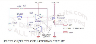
I wonder why he used two CD4069 hex inverter ICs, instead of one CD4027 dual JK flipflop IC?... he is making a T-flipflop (push on, push off) out of CD4069 CMOS inverters ...
Both chips are in my 1983 RCA CMOS databook, so they were both available in ~1989 when the preamp was designed. Today the two chips sell for the same price; in 1989 I suspect their prices were very close as well. The JK flipflop implementation requires one fewer passive component than the hex inverter implementation, so it wasn't external parts count/cost either. Maybe he farmed out that little piece of design work ("eww! it's digital! yuck!") to a summer intern or something.
My Jeff Rowland Coherence One "rebuild"
https://www.facebook.com/buranostromo/media_set?set=a.10202427084070759.1073741832.1603459110&type=1
https://www.facebook.com/buranostromo/media_set?set=a.10202427084070759.1073741832.1603459110&type=1
My Jeff Rowland Coherence One "rebuild"
https://www.facebook.com/buranostromo/media_set?set=a.10202427084070759.1073741832.1603459110&type=1
Thank you very much for this informations and imagesIt is a MIL specified capacitor from the 1980's. See data sheet:
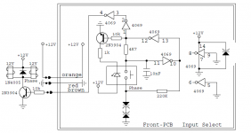
new questions are rises up. There are for each channel an inverted modul (for the invert output) and a non inverted modul (for the normal output). Additional there is a function-button (pushbotton) on the face plate, that is call "Phase REV".
This works effectively at both kind of outputs (i. e. at both line amp modules). I see no advantages for this approach at first look.
What purpose is to be fulfilled by this phase toggle switch ?
I also don't find advices there:
http://jeffrowlandgroup.com/kb/questions.php?questionid=485
(Owner's Manual).
Clearly disadvantage is an additional unwanted relais contact in the signal pad through this (at least for me).
Last edited:
Last updates - schematics now finished, so I think.
In case of the phase mode select (normal and reverse) I note some trouble concerning the current flows (quiescent/idle current) by the modules used in the left channel:
1) a. The inverting LINE AMP current flow is correct in the position "PHASE REVERSE ON" (+/-45,7mA) and
1) b. The non inverting LINE AMP current flow is correct in the position "PHASE REVERSE OFF" (+ 44,9mA and - 45,1mA)
2) a. The inverting LINE AMP current flow isn't correct in the position "PHASE REVERSE OFF" (+33,5mA and - 95,5mA | associated module runs hot).
2) b. The non inverting LINE AMP current flow isn't correct in the position "PHASE REVERSE ON" (+ 33,3mA and - 93,3mA | associated module runs hot).
Mixing up resp. interchanging cross the modules from left channel to right channel and vise versa brought clarity about the fact, that the error is not coming from the modules itself.
Attachments
Last edited:
Thank you very much for this informations and images
New questions are rises up. Additional there is a function-button (pushbotton) on the face plate, that is call "Phase REV".
What purpose is to be fulfilled by this phase toggle switch ?
This is explained here in this video by Mr Huber at 6.30 min.
FM 223 - YouTube
Thank you. Unfortunately I am no computer specialist and no it expert.This is explained here in this video by Mr Huber at 6.30 min.
FM 223 - YouTube
for copyright reasons this video isn't available for Germany.
To get nevertheless this video I must go on the web by proxy server (like at several music videos on youtube).
What I must do therefore?
There are for each channel an inverted modul (for the invert output) and a non inverted modul (for the normal output). Additional there is a function-button (pushbotton) on the face plate, that is call "Phase REV".
This works effectively at both kind of outputs (i. e. at both line amp modules). I see no advantages for this approach at first look.
What purpose is to be fulfilled by this phase toggle switch ?
Some people believe the human ear can detect absolute phase. For example, a kick-drum produces an air pressure waveform that begins with a "rising edge" (compression) rather than a "falling edge" (rarefaction). Some people believe that when they play a kick-drum beat through an amplifier and loudspeaker twice, first with phase noninverted, and again with phase inverted, they can hear a difference between these two playback experiences. Further, they believe the phase noninverted playback sounds more natural than the phase inverted playback.
So, for those people, Jeff Rowland offers the option of phase inversion. Listen to a particular source with phase noninverted. Listen again with phase inverted. Do you prefer one more than the other? Perhaps that's because the mastering process (which sends the musical signal through dozens of signal processing modules, some unknown number of which are inverting) was phase-inverting. Jeff Rowland offers the option to correct that in playback. {It's also a fun little experimental apparatus that may help you decide whether or not YOU can hear absolute phase. Play (The Sheffield Drum Record) and find out!}
Thank you. Unfortunately I am no computer specialist and no it expert.
for copyright reasons this video isn't available for Germany.
To get nevertheless this video I must go on the web by proxy server (like at several music videos on youtube).
What I must do therefore?
Try the instructions here:
Steps to bypass YouTube’s region restrictions | The Tech Corner
I agree with Mark Johnsons answer.
Last updates - schematics now finished, so I think.
In case of the phase mode select (normal and reverse) I note some trouble concerning the current flows (quiescent/idle current) by the modules used in the left channel:
1) a. The inverting LINE AMP current flow is correct in the position "PHASE REVERSE ON" (+/-45,7mA) and
1) b. The non inverting LINE AMP current flow is correct in the position "PHASE REVERSE OFF" (+ 44,9mA and - 45,1mA)
2) a. The inverting LINE AMP current flow isn't correct in the position "PHASE REVERSE OFF" (+33,5mA and - 95,5mA | associated module runs hot).
2) b. The non inverting LINE AMP current flow isn't correct in the position "PHASE REVERSE ON" (+ 33,3mA and - 93,3mA | associated module runs hot).
Mixing up resp. interchanging cross the modules from left channel to right channel and vise versa brought clarity about the fact, that the error is not coming from the modules itself.
The reason for this is the present of unwanted oscillation (arround 1MHz, sine wave). This oscillation is to obeserve at all places. The highest level I note at the +/-20V rails between power supply and preamp section.
If I put my hand on the devices from power supply PCB the oscillation disappears (and the amp works perfect without differences at the current flows) and if I take away the hand, the oscillation is back.
Have a look to the schematics. In post #40 I ask follow:
Whether too much whiskey bottles could have been present during the circuit design?
Now I know, that was not the whiskey, but a not always successful attempt to avoid such unwanted oscillation.
The question is now, how I find and perform a correction of the circuit (I don't like to add several caps at different places according to the method "trial and error").
I don't like having to perform the actually job from Jeff Rowland, but what else should I do ?
Last edited:
Perhaps there are one or more failed solder joints, cracked PCB traces, solder bridges, intermittent connections, or failed electronic components in your preamp. Perhaps other units of this same preamp design do not oscillate, because they lack these failures.
Which is also possible, but not very likely, if you have a look to the circuit diagram.
Check out again in this case post #53 (second and third question).
Additional curious for me is the serial resistor for both power supply output capacitors.
If I short this resistors, the level of unwanted oscillation goes strongly down.
What is the aim for such serial resistances of blocking caps (resistors at such places I have never seen before) ?
Why goes the 100uF capacitor at the base of 2N3440 (power supply) not to GND?
Questions and more questions to this very special circuit topology of the used power supply.
Last edited:
Which is also possible, but not very likely, if you have a look to the circuit diagram.
Check out again in this case post #53 (second and third question).
Additional curious for me is the serial resistor for both power supply output capacitors. Looks like a Zobel
If I short this resistors, the level of unwanted oscillation goes strongly down.
What is the aim for such serial resistances of blocking caps (resistors at such places I have never seen before) ?
Why goes the 100uF capacitor at the base of 2N3440 (power supply) not to GND? GND and the negative rail are filthy with noise. The output of the opamps to which the 100uF caps are connected is clean
Questions and more questions to this very special circuit topology of the used power supply.
- Home
- Amplifiers
- Solid State
- Jeff Rowland Coherence 1 - Schematic for the Modules wanted