Maybe there is AM radio station close by; or other sources from equipment in your lab.
Will oscillation disappear if the exposed PCBs are covered with the preamps metal cover [and grounded]?
Will a 10 MegOHM [or less] resistor connected where [you touch] and then to earth cure oscillation?
Will oscillation disappear if the exposed PCBs are covered with the preamps metal cover [and grounded]?
Will a 10 MegOHM [or less] resistor connected where [you touch] and then to earth cure oscillation?
The reply is no in all cases. I still don't know the exact reason. But the main oscillation source are the phono modules for high level. Removing both - one module or both of the modules brings the oscillation to disappear.Maybe there is AM radio station close by; or other sources from equipment in your lab.
Will oscillation disappear if the exposed PCBs are covered with the preamps metal cover [and grounded]?
Will a 10 MegOHM [or less] resistor connected where [you touch] and then to earth cure oscillation?
But only the connection of just this two modules (phono high level = second phono gain stage) to VCC and VEE let occur the oscillation.
One of the modules has a font color of white and the other dark blue - go to the pictures from the posts at beginning.
Maybe different devices inside? Current flow is nearly identical.
If I remove the high level phono modul at left channel and then at right channel the amp works fine in both cases (white noise without cartridge connection is much lower as before).
There is no possibility for inducing any oscillation again under this condition.
Now I need additional phono high level modules for further troubleshooting.
Where I can ask therefore?
supplement to post #34:
go to last image about this link:
http://www.audiocircle.com/index.php?topic=93368.0
Last edited:
The reply is no in all cases. I still don't know the exact reason. But the main oscillation source are the phono modules for high level. Removing both - one module or both of the modules brings the oscillation to disappear.
But only the connection of just this two modules (phono high level = second phono gain stage) to VCC and VEE let occur the oscillation.
One of the modules has a font color of white and the other dark blue - go to the pictures from the posts at beginning.
Maybe different devices inside? Current flow is nearly identical.
If I remove the high level phono modul at left channel and then at right channel the amp works fine in both cases (white noise without cartridge connection is much lower as before).
There is no possibility for inducing any oscillation again under this condition.
Now I need additional phono high level modules for further troubleshooting.
Where I can ask therefore?
supplement to post #34:
go to last image about this link:
Used Rowland M1 amp: should I worry about reliability?
Removing the modules to detect the cause was a thinking error.
The introduce of appropriate resistances to get the same current flow (2x 470Ω/each module) provides again the unwanted oscillation. The reason now is clear. The discrete voltage high speed regulators works than an oscillator under certainly current flows. The replace of this four-transistor regulator through a resistor (at whole 16 pieces) eleminate the wild and unwanted swing resp. oscillator effects.
This means, that a redesign for the regulators is necessary.
Maybe there are threads here on diyaudio to this topic concerning the design rules.
Hello tiefbassuebertr. I am glad that you found the cause of the oscillation, and are pursuing a solution. The Belleson replacements for LM317, and LM337 came to my mind as an option. May also consider using a clean "bench" power supply to drive the modules in their places. Is it possible that the oscillation is actually in the modules [also high gain; prone to oscillation too], and is kicked out to appear as a regulator problem? Is the schematic of the suspect regulator like the one that you showed earlier; but has only has 3 bjts?Removing the modules to detect the cause was a thinking error.
The introduce of appropriate resistances to get the same current flow (2x 470Ω/each module) provides again the unwanted oscillation. The reason now is clear. The discrete voltage high speed regulators works than an oscillator under certainly current flows. The replace of this four-transistor regulator through a resistor (at whole 16 pieces) eleminate the wild and unwanted swing resp. oscillator effects.
This means, that a redesign for the regulators is necessary.
Maybe there are threads here on diyaudio to this topic concerning the design rules.
Best regards.
Hello tiefbassuebertr. I am glad that you found the cause of the oscillation, and are pursuing a solution. The Belleson replacements for LM317, and LM337 came to my mind as an option. May also consider using a clean "bench" power supply to drive the modules in their places. Is it possible that the oscillation is actually in the modules [also high gain; prone to oscillation too], and is kicked out to appear as a regulator problem? Is the schematic of the suspect regulator like the one that you showed earlier; but has only has 3 bjts?
Best regards.
No, this isn't the case.
Conclusion of the troubleshooting is now noted - follow hard to find errors was present - most likely already from new condition:
A: Unwanted connection between two PCB traces provides follow unwanted functions:
1) sometimes (not always) offset at one of the outputs from left channel (the use of the switch for phase reverse mode produce sometimes a hard popping in the speakers)
2) sometimes (not always) no action at the relais for the switch-on delay resp. mute function (both comands produce a shorting between output and GND - the short function is remove after the "ready" mode several seconds after switch on by a good working preamp device of this model)
The reason therefore was a transition resistance between two wire routings on the PCB (PCB traces); first copper path is those from the collector of the darlington transistor to the relais resp. anode of the protection diode (go to the schematic PDF "function") and second copper path is those from the output resistor/output female cinch connector to the not used resistor in the section for opening the output relais contact three seconds after switch-on.
The last picture of post 65 (main board solder site) shows the not really good to find place:
go therefore between the second and third output connector (counted from left hand); 1 cm below the upper edge of the PCB. at this area there is to find an unused place for a resistor with two open holes for soldering points.
The bottom of these holes is the PCB trace for the output signal in front of the 150 ohm resistor.
right hand of this open hole - slightly upward - there is the end of the anode wire so as the soldering point of the protection diode, type 1N4005.
The associated PCB trace therefore is those from the collector of the darlington transistor MPSA14.
An incision with the cutting disc above this soldering point of the protection diode (anode) isolated the PCB trace above (for the output signal behind the phase switch relais resp. in front of the the 150 ohm output resistor), and eliminated the undesirable effects mentioned by number 1) and 2)
B: Unwanted oscillation at all of the so called high speed voltage regulators (in reality, electronic inductors or capacity multipliers) due an unprofessionally performed circuit design.
Arround the phono high level modules there was a 1MHz sine wave and arround the phono low level modules a 17 MHz sine wave - even without the modules itself and alternatively soldered resistors of 470Ω between the pos. and neg. voltage output and earth resp. GND.
Highest level I had observe between the NPN darlingtons and the PNP darlingtons (collector-base-150Ω connection) - and actually in all 16 pieces (eight times positive and eight times negative regulators - go to the schema for PS).
Both mentioned unwanted errors did not occur due to aging and stress of the used electronic components.
This means clearly, both mentioned unwanted errors already exist in new condition from the first used day.
Is not that amazing ??
How many devices of this preamp model are still in use and how many devices lie unused on any attic due such condition as described here?
Last edited:
Congrats !
I have another example for such a badly oscillating preamplifier:
Sony TA-E88B
I own five pcs (in different variations TA-E88/TA-E88B/Wega lab Zero Pre).
Three of them oscillated, two of them only with volume pot to maximum.
The other one oscillated even at lower volume settings.
Here the line amplification stage after the volume pot was to blame for.
A smallish capacitor (220pF, Styroflex) parallel to it's input solved the problem.
The fact, that the oscillation is depending on volume pot setting let me easily find the source of the problem. As you learned some oscillation problems are much more difficult to cure than this one.
In case of the Sony TA-E88B one can easily understand, that many people say, that this device is one of the best (Japanese) pre amps of all time , but some people say, they are less than impressed about their's ... probably just because some of these devices tend to oscillate, which kills the good sound.
I'm pretty sure, that many assumptions like: "Devices, which tend to measure the same, may sound different" etc. have probably often to do with the fact that these devices tend to oscillate in some setups or not. The same with current (SOA) clipping in many badly executed power amp designs.
I have another example for such a badly oscillating preamplifier:
Sony TA-E88B
I own five pcs (in different variations TA-E88/TA-E88B/Wega lab Zero Pre).
Three of them oscillated, two of them only with volume pot to maximum.
The other one oscillated even at lower volume settings.
Here the line amplification stage after the volume pot was to blame for.
A smallish capacitor (220pF, Styroflex) parallel to it's input solved the problem.
The fact, that the oscillation is depending on volume pot setting let me easily find the source of the problem. As you learned some oscillation problems are much more difficult to cure than this one.
In case of the Sony TA-E88B one can easily understand, that many people say, that this device is one of the best (Japanese) pre amps of all time
, but some people say, they are less than impressed about their's ... probably just because some of these devices tend to oscillate, which kills the good sound.I'm pretty sure, that many assumptions like: "Devices, which tend to measure the same, may sound different" etc. have probably often to do with the fact that these devices tend to oscillate in some setups or not. The same with current (SOA) clipping in many badly executed power amp designs.
in the meantime I know, that the realibility of this preamp is very bad, as you can see by image from last post under
Used Rowland M1 amp: should I worry about reliability?
In the meantime I have heard from two different owners about the same issue.
This means for me, that there are a lot of devices from this model without correct operation and without any function.
I am now looking for such fauty devices for spare parts. Who can offer such faulty resp. defective preamp devices ?
Perhaps such devices are in some shops in the farthest corners.
Thank you for informations.
I am looking for new relais for the input (source) select of this model.
By the PDF URL under
http://www.hongfa.com/pro/pdf/HF115F_en.pdf
there are mentionned various contact materials.
Which is the best choice?
Best thanks for advives.
By the PDF URL under
http://www.hongfa.com/pro/pdf/HF115F_en.pdf
there are mentionned various contact materials.
Which is the best choice?
Best thanks for advives.
I am still looking both for such fauty devices so as for modules in faulty condition to create an own schematic.in the meantime I know, that the realibility of this preamp is very bad, as you can see by image from last post under
Used Rowland M1 amp: should I worry about reliability?
In the meantime I have heard from two different owners about the same issue.
This means for me, that there are a lot of devices from this model without correct operation and without any function.
I am now looking for such fauty devices for spare parts. Who can offer such faulty resp. defective preamp devices ?
Perhaps such devices are in some shops in the farthest corners.
Thank you for informations.
Only two to go....

Now serious.
Jeff Rowland is together with Nelson Pass in my opinion one of the nicest guys within the world of the high-end audio.
I'm communicating with him (and Nelson) for over 25 years now regarding their products and they always helped me out.
I've had expensive pre-amps from Levinson, Krell, Threshold and Audio-Research and the C1 in its different incarnations is to me the most musical sounding of them all.
You can see that he's still updating his first commercially available pre-amp (1986). Remember all the modular Levinsons? They were never updated although MLAS & Madrigal used the modular construction as a selling point against obsolence.
These new line level modules are only $ 300.00 the four so not $ 400,00 a piece as I saw mentioned somewhere in this thread.
Do not know the exact price of the High Level Phono modules but they're probably somewhat more expensive then the line level ones.
Jeff sended me the latter for a wrong level potted phono module and charged only that one, great!
PSU still runs pretty hot but less the with the potted modules.
Sound is still mellow but there's more background detail, more air, crispness, instrument's are more defined and separate, sound has more extension and depth.
Hope you all enjoy you C1's and maybe you will get the updates that are OPEN so you can see what's on them instead of using X-Rays or 500 degrees Heat canons,
Cheers Robert
Attachments
Last edited:
Interesting informations. But hard to believe, that the new not pottet modules with an integrated dip-8 op-amp provides better sonic quality. Of course - the type number on the surface is removed. Maybe a LM4562 or a AD797. Or brand new models where the upper supply voltage limit is above +/- 20VDC. Burson Audio recommend the reverse solution: an op-amp in a discrete 12-transistor design instead an integrated design. This seems to me the more convincing approach.Only two to go....
Now serious.
Jeff Rowland is together with Nelson Pass in my opinion one of the nicest guys within the world of the high-end audio.
I'm communicating with him (and Nelson) for over 25 years now regarding their products and they always helped me out.
I've had expensive pre-amps from Levinson, Krell, Threshold and Audio-Research and the C1 in its different incarnations is to me the most musical sounding of them all.
You can see that he's still updating his first commercially available pre-amp (1986). Remember all the modular Levinsons? They were never updated although MLAS & Madrigal used the modular construction as a selling point against obsolence.
These new line level modules are only $ 300.00 the four so not $ 400,00 a piece as I saw mentioned somewhere in this thread.
Do not know the exact price of the High Level Phono modules but they're probably somewhat more expensive then the line level ones.
Jeff sended me the latter for a wrong level potted phono module and charged only that one, great!
PSU still runs pretty hot but less the with the potted modules.
Sound is still mellow but there's more background detail, more air, crispness, instrument's are more defined and separate, sound has more extension and depth.
Hope you all enjoy you C1's and maybe you will get the updates that are OPEN so you can see what's on them instead of using X-Rays or 500 degrees Heat canons,
Cheers Robert
I still looking for the internal circuit diagram of the old modules respective old modules without working for opening this to create my own schematic.
Last edited:
Line:
U1: (small transistor) LM78L, Positive Voltage regulator
U2: (small transistor) MC79L, Negative Voltage regulator
U3: (8 PIN IC): Analog Device, AD746N
C1 & C3: 16V 100 uF (electrolytic caps)
C2 & C4 (blue): 104 (0,1 uf)
C5 & C6 (brown): 100 (10 pF)
Phono is the same except for additional:
ERO CAP: MKC1862 1uF
At your service... ;-)
Greetings Robert
Thank you very much for this informations. According datasheet the absolut maximum rated voltage for AD746N is +/- 18Vdc. Which value has the voltage regulators?Line:
U1: (small transistor) LM78L??, Positive Voltage regulator
U2: (small transistor) MC79L??, Negative Voltage regulator
U3: (8 PIN IC): Analog Device, AD746N
C1 & C3: 16V 100 uF (electrolytic caps)
C2 & C4 (blue): 104 (0,1 uf)
C5 & C6 (brown): 100 (10 pF)
Phono is the same except for additional:
ERO CAP: MKC1862 1uF
At your service... ;-)
Greetings Robert
Who have both different phono modules in not working condition ?I am still looking both for such fauty devices so as for modules in faulty condition to create an own schematic.
The most important steps for the power supply service I have describe here about post #9:
http://www.diyaudio.com/forums/pass...-one-series-i-ii-powersupply.html#post4200168
I am still looking for single phono modules (1+2)
http://www.diyaudio.com/forums/pass...-one-series-i-ii-powersupply.html#post4200168
I am still looking for single phono modules (1+2)
Any news?I am still looking both for such fauty devices so as for modules in faulty condition to create an own schematic.
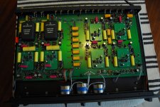
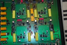
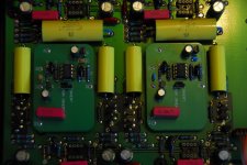
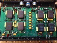
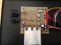
Another Variation
I'm a bit late to the game, but attached are some pics of my Coherence Series 1 for comparison to the ones posted on page 1.
Note that the modules all have smooth metal casings except for the low-level phono which has the textured casing. In the pictures on page 1, all of the modules have the textured look. I don't know the significance of this...if any.
The power supply I have doesn't look like any other I've seen on the net...the layout is completely different from the one here:
http://www.diyaudio.com/forums/pass-labs/228183-jrdg-coherence-one-series-i-ii-powersupply.html
My power supply used to have 4 radial caps in the middle of the board, but those were replaced with the 2 Elna caps that are now mounted off the board. Those 2 caps have more capacitance than what was originally mounted. Also, some of the small caps were replaced with Panasonics.
That work was done by Mr Rowland himself. I live about 10 minutes from his shop and I was able to drop the Coherence off personally. I can confirm what was said about him above...he is an absolute gentleman and has been incredibly accommodating when I have called/visited him. Some of you have questioned his desire to keep his designs under wraps, and while I understand your argument, please do NOT conflate a single business decision with his who he is as a person. That is a dangerous habit.
On a slightly different note, when I picked up my preamp (I got to watch Jeff check the noise levels), I also dropped off my Model 1 amp to be worked on. He showed me updated boards for the Model 1 he had just received and I agreed to have him update the amp...I'm very interested to hear those results.
Jeff
(yes, my name is Jeff too...)
Attachments
- Home
- Amplifiers
- Solid State
- Jeff Rowland Coherence 1 - Schematic for the Modules wanted