This sounds even more stupid than the fake manufacturer's position.
Well, the reality is very stupid and in needs of logical explanation.
However, I think Fairchild would have admitted to such a commercial arrangement. These days they avoid it with Korean markings like KSC for 2SC or their own ID like FJP...etc. series, I believe.
Hey, there is similar situation with MT-200 Sanken marking! The most popular Sanken here is marked with 5DY. The price is around $3.6 a pair. A big seller once told me that the first digit is associated with the maximum Vce. 5DY means a maximum of 2x50V. Some years ago, some sellers sell many types of MT-200 Sanken with different pricing. The higher the first digit, the more expensive. But I could only found a marking starting with "5" to "8" (I think the original has "0" marking, or at least "9").
I have seen many fake Sankens marked with "0". That is logical. The question is with the structured unique batch marking scheme.
Last edited:
I'm answering this literally, I hope that is what the intention of the question was 🙂
Pb is the symbol for lead. Pb free transistors do not have any lead used in their manufacture. Due to Occupational Health and Safety concerns the use of lead in certain countries has been banned.
As for whether the presence or lack of lead affects the performance of the transistors, the datasheets should be able to tell you that.
As a guess, I would say that likely the only place there will be lead present is on the tinning on the leads, in which case the difference will be the use of leaded, or lead free solder for the tinning.
Tony.
What is the differentes between Pb free transistors and non Pb free?
Ok, Pb free=Lead free
WOULD YOU HELP ME ?


View attachment 2SA 1930.pdf
Ok, Pb free=Lead free
WOULD YOU HELP ME ?
View attachment 2SA 1930.pdf
What is the differentes between Pb free transistors and non Pb free?
Ok, Pb free=Lead free
WOULD YOU HELP ME ?
View attachment 256453
View attachment 256454
View attachment 256455
Ok, Pb free=Lead free
WOULD YOU HELP ME ?
View attachment 256453
View attachment 256454
View attachment 256455
What is the differentes Specification between lead free transistors (Right 2SA1930) and non lead free (Left 2SA1930) ?what is the question?
What is the differentes Specification between lead free transistors (Right 2SA1930) and non lead free (Left 2SA1930) ?
Use normal forum fonts to type whole sentences please. Thanks.

I cannot see the manufacturer admitting to any specification differences between the two types.
I will throw in one of my own.
The lead free plating is not as universally amenable to easy and reliable soldering.
If that is an answer to your question, but I still can't truly understand what you ask.
I will throw in one of my own.
The lead free plating is not as universally amenable to easy and reliable soldering.
If that is an answer to your question, but I still can't truly understand what you ask.
Manufacturers are still changing their tinning processes from lead solder and clearing old stock. For example, On-Semi supply part numbers with a G suffix to denote Pb-free, whilst no suffix or A suffix may mean it still uses lead solder tinning. It is easy to read the manufacturer's data sheets to discover such details if you think they help you.
However, it seems you are trying to distinguish fakes with this detail. I think you are bound to have more difficulty with this than you can imagine since your suspicions may be correct or not, depending on the date, package and marking process of the actual manufacturing plant. Many Semiconductor manufacturers are globalized and use licensed production elsewhere so you cannot be certain whether your fakes are identical or very poor substitutes.
Some stocks, globally, are known to exceed 10 years from some sources so you can see that as the manufacturer changes his process and markings, you will need to become an expert historian to identify and predict fakes. Few of us here will ever see some Asian manufactured fakes so there will be limits to our help too.
In my limited experience, it is better to recognize the fonts and precision of markings and check your supplier's integrity and reputation "on the street" - not from official nonsense.
Again, your source's integrity is your only guarantee and you will not be any more satisfied if we can't confidently identify the markings on a particular part you have.
You should test Vceo as a first indication that your part is within that spec. and then consider other faults. A suitable breakdown voltage tester for this is not always available but they are not complex or hard to construct for use with a DVM.
Ha!
speaking of which, look at the leads of those transistors on the picture, especially the right one. It's so poor that looks like someone manually tinned those leads with a soldering iron! 😀
speaking of which, look at the leads of those transistors on the picture, especially the right one. It's so poor that looks like someone manually tinned those leads with a soldering iron! 😀
Is measurement of bipolar transistor Ft any use in determination of fake status? I have a very simple circuit from an old Wireless World that can measure the approx Ft, I built it at the time and it worked but it vanished in a house move many moons ago. I would be willing to build it again if measuring Ft were a good method.
Transistors tolerance

Test Condition : VCE=4.4v ; IC=11mA ; Accuracy=10%
As a sample, I have measured HFE of 10 transistors out of 200 transistors as following :
HFE1=137 HFE2=122 HFE3=110 HFE4=157 HFE5=122
HFE6=110 HFE7=137 HFE8=183 HFE9=100 HFE10=122
Could this wide variation of HFE be for a high grade transistors(2SC3790E) ?
View attachment 2SC 3790 , 2SA 1480.pdf
The single specification for a complementary pair BJT must be very general, by logical consideration alone. However, the spread of Hfe looks to be within grade E limits. Did you anticipate a tighter than specified range?
As a video driver for CRT televisions, a tight or rather, selected range of Hfe is not needed or offered, I think. In audio application, a tighter spec. requirement can not change what the manufacturer supplies just to suit an unknown alternate use.
Perhaps you could consider parameter spreads for any transistors. I believe only expensive power transistors are supplied with close matching to suit high power arrays. This service is not free - you pay more for it.
Whilst Hfe is an easy test, it is easy to fake and exceed using smaller dies for power transistors. What is not so easy is SOA (Safe Operating Area), which really matters.
Vceo is an indicator as well as Ft and Hfe at near working current in power transistors but these may require more effort to prove.
On the good side, so far, with a simple test, your transistors read fine. 🙂
Last edited:
TBH, I don't know how telling this will be for small signal transistors but it could sort the substitution of cheap power transistors for modern high Ft types in amplifiers. That would be a huge benefit if it worked for the largest transistors too.Is measurement of bipolar transistor Ft any use in determination of fake status? I have a very simple circuit from an old Wireless World that can measure the approx Ft, I built it at the time and it worked but it vanished in a house move many moons ago. I would be willing to build it again if measuring Ft were a good method.
I say 'go for it!' Let's see the details too, if you have the time.

TBH, I don't know how telling this will be for small signal transistors but it could sort the substitution of cheap power transistors for modern high Ft types in amplifiers. That would be a huge benefit if it worked for the largest transistors too.
I say 'go for it!' Let's see the details too, if you have the time.
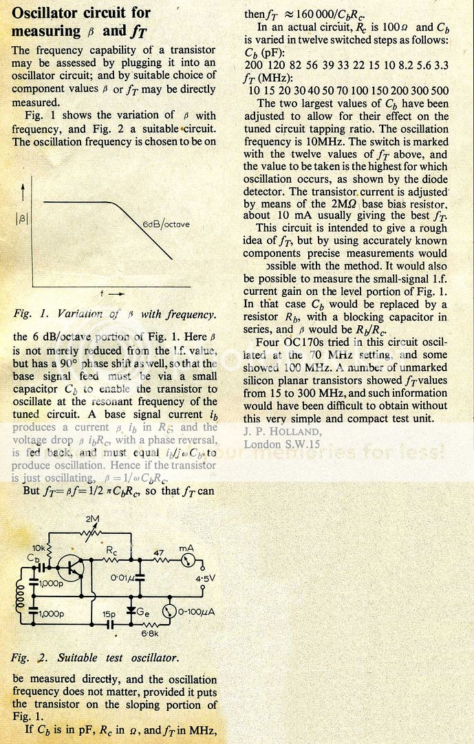
It's based on this Circuit Idea from WW circa Dec 1970. As I say it worked fine. You rotate the switch until there's oscillation output and read off the Ft from the marked switch position. There's no need for the meters, really, a couple of LEDs and switching transistors should be enough to take their place. A reduced oscillation frequency may be better for power transistors, perhaps 2 coils switched for 10MHz & 1 MHz.
If there's copyright problems can a moderator take it down.
need another transistor. do you think those are fakes?
2pair of 2SA1695 + 2SC4468 Transistor A1695 + C4468 | eBay
i contacted the seller and he insists on selling originals, but can you trust in this?
2pair of 2SA1695 + 2SC4468 Transistor A1695 + C4468 | eBay
i contacted the seller and he insists on selling originals, but can you trust in this?
Surely we are allowed to post a 41year old article from an electronics magazine.
I am reporting my own post and hope the Moderating Team can post somewhere on the Forum what the ruling is on very old copyright.
I am reporting my own post and hope the Moderating Team can post somewhere on the Forum what the ruling is on very old copyright.
need another transistor. do you think those are fakes?
2pair of 2SA1695 + 2SC4468 Transistor A1695 + C4468 | eBay
i contacted the seller and he insists on selling originals, but can you trust in this?
The only seller I trust on ebay from that part of the world regarding transistors is Electronics Salon (Audiowind).

2SA1695 & 2SC4468 Original SANKEN Transistor, x 2 Pairs | eBay
- Status
- Not open for further replies.
- Home
- Amplifiers
- Solid State
- Are these 2SC5198 fake?