A great result considering the possibilities there.
The biasing pot is smaller but I don't know that would have much effect at RF compared to the 2M pot.
Have you verified the oscilllation frequency and checked an old germanium transistor like an OC71 or any AM radio type from the dawn of solid state?
Perhaps there's an issue there somewhere, though I guess you tested silicon types more often by the 1970s anyway. I never worked with germanium types after I dropped valves in the late 60s so my experience is almost zero there.
The frequency is about 950kHz in practice. The inductor can take a ferrite slug and I can drop the frequency to about 800kHz which doesn't make much difference so I don't think getting it up to 1MHz will help. I can remember testing small silicon transistors with the original circuit and getting the correct 300MHz reading, I had bypassed germanium also by the time I built the original. The worst 2 power transistors I possess are a 2N3055 which gives a reading of 1MHz Ft, the datasheets show 3MHz but that's at 10v and 0.5A, and a 2N5296 which also oscillates at the 1MHz setting and is supposed to have an Ft of 0.8MHz but that's rated at 0.2A which is closer to my device's best current of approx 60mA or so. As for small devices, a 100MHz one only goes to the 30MHz mark, but a 250MHz one lights up at the 50MHz mark, both at 10-20mA.
I'm thinking it's probably the approx 4 inch leads I've had to use to have flying leads with crocodile clips for connecting to power transistors that may be the problem, but there's no alternative without a proper rebuild from scratch rather than hacking an old project. Despite it's drawbacks I think it may prove a useful box of tricks to root out obvious fakes. Now I need an HV supply in a small box to make a Vceo meter.
This doesn't seem so bad for the power transistors. It depends on manufacturers of course, but Motorola, used only quote 800kHz for 2N3055 yet ST quoted 2 or 4 MHz at one time. Pretty well all native Motorola/On Semi power semis are only 4MHz, including MJ21193/4 and plastic variants.......The worst 2 power transistors I possess are a 2N3055 which gives a reading of 1MHz Ft, the datasheets show 3MHz but that's at 10v and 0.5A, and a 2N5296 which also oscillates at the 1MHz setting and is supposed to have an Ft of 0.8MHz but that's rated at 0.2A which is closer to my device's best current of approx 60mA or so. As for small devices, a 100MHz one only goes to the 30MHz mark, but a 250MHz one lights up at the 50MHz mark, both at 10-20mA.......... Now I need an HV supply in a small box to make a Vceo meter.
It seems the problem may be with small signal types and given the relatively high current, perhaps they need to oscillate with lower current??

The 150-200V supply needs only a sniff of current and having built a couple of BVceo testers in kit transistor testers, I recall these as simple square wave or UJT oscillators powered off the main 6-9V supp]y driving a $1, 500R:8R miniature output transformer and then via a 600V diode, small HV cap and resistor to the DUT. It used its own meter for all of eight tests but contacts for DVM probes would be simpler.
Searching "zener tester" should bring up a suitable design but lower voltage supply.
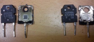
More fake 5198
I've just ordered 4 pairs of 1941/5198 from a reputable (so far!) supplier.
When fitted to the amp, the amp went DC and one of the new transistors went short.
I've cracked one of the new ones open, and compared it with a genuine toshiba.
Here is the result. Opinions??
I've just ordered 4 pairs of 1941/5198 from a reputable (so far!) supplier.
When fitted to the amp, the amp went DC and one of the new transistors went short.
I've cracked one of the new ones open, and compared it with a genuine toshiba.
Here is the result. Opinions??
Attachments
Schematic request..
Hello,
Is it possible to have the schematics of the Ft measuring circuit that you built?. I would like to test some transistors to determine if they are fakes. I think this measurement will reveal this.
Thank you,
Jose
It's based on this Circuit Idea from WW circa Dec 1970. As I say it worked fine. You rotate the switch until there's oscillation output and read off the Ft from the marked switch position. There's no need for the meters, really, a couple of LEDs and switching transistors should be enough to take their place. A reduced oscillation frequency may be better for power transistors, perhaps 2 coils switched for 10MHz & 1 MHz.
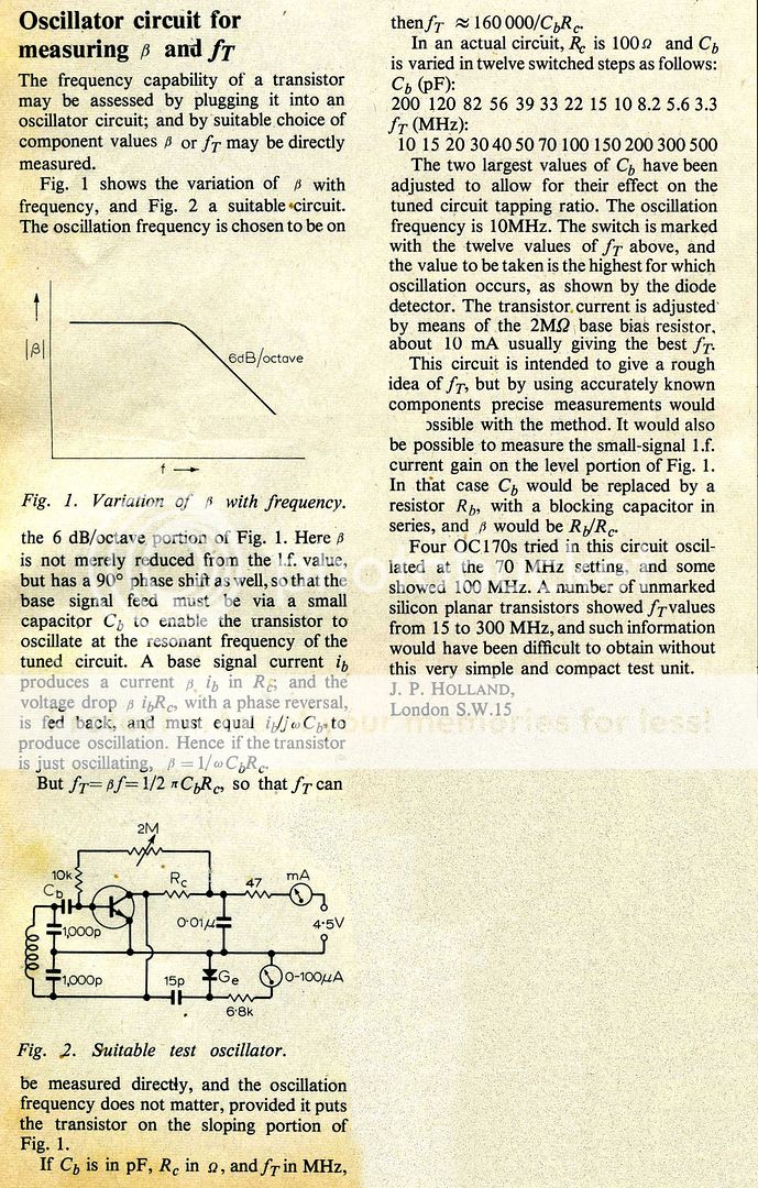
If there's copyright problems can a moderator take it down.
Hello,
Is it possible to have the schematics of the Ft measuring circuit that you built?. I would like to test some transistors to determine if they are fakes. I think this measurement will reveal this.
Thank you,
Jose
- Status
- This old topic is closed. If you want to reopen this topic, contact a moderator using the "Report Post" button.
- Home
- Amplifiers
- Solid State
- Are these 2SC5198 fake?