Aluminum would work to. Dont know how strong the nylon will be but as long as you do not over tighten it, it should be fine. AndyNo luck finding any brass bolts, closest I came was a store that had threaded brass rods, but they were expensive!

Look very carefully at the PSU schematic.
Use a series pair of smoothing caps, use a single bridge rectifier. Temporarily remove the CT to Zero Volts wire connection.
.
.
Can you see the figure of 8 for the charging current?
These coloured in current routes are the charging circuit.
.
.
By keeping the current routes separate you avoid the voltage drop in one circuit affecting the voltage in another circuit.
Most of these circuits need to reference themselves to other circuits. Do this by allowing the separate circuits to "touch" (not share) each other at a point. This point is the Main Audio Ground.
Thanks for the excellent tutorial Andrew.. I trimmed just to reduce the size of the quote. I actually followed this approach (multiple separate earth returns to single star point) with my P2P chipamp, but it will be worthwhile me doing the excercise on paper to better understand the current flows!
Tony.
Last edited:
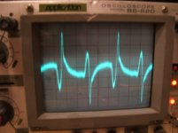
Those spikes look like charging pulses (plus possibly a diode switch-off spike), so the secondary/rectifier/cap loop is either generating a magnetic field or contaminating a ground.
Thanks DF96 (I assume you are referring to the last traces I posted), Both channels are sharing the same PS, bog standard single rectifier with two 8,000uF caps in parallel per rail. Star point is on the PCB and is shared by the two channels.... So I think that it has to be induced noise in this case since one channel is completely clean... The speaker connections are not symetrical with a long wire connecting from the right channels output to the zobel and speaker protection relay on the left channel side of the single PCB . Also the +- wiring for the right channel is longer than that for the left. I think that the combo of the transformer sitting directly under this channel and the asymetries are causing the problem.
Elbert, yes it should be possible to change the layout, and was the plan for the new PS. I had a look last night and I actually can fit in both toroids and all my filter caps will require some re-gigging but should be possible.. the PS's not performing the same under load was what worried me, but I guess since this amp is destined to only drive my subs up to 300 Hz I shouldn't be too concerned
")
I should be able to take the chipamp toroid out quite easily (but would only do so if my three year old wasn't at home) I would like to know, whether the cause in that case is the PS or induced.. certainly from what DF96 and Andrew have said, the PS seems the culprit (though my implementation is only single bridge per channel), but in this particular case I'm not 100% sure, I believe that my implementation shouldn't have the same issue yours does, but it's certainly possible and only testing will reveal if it is the case). It won't be in the short term though. Too many other things that need to be finished!
Tony.
OK so I couldn't resist. My daughter is at daycare and I'm working from home today, so during my lunch hour, I took the front pannel off the chipamp (torroidal is mounted there) and lay it on the floor. Did the scope measurements in this position and also with it in the normal position. Absolutely no discernable difference to the naked eye. Haven't downloaded the pics yet as I have my work laptop connected up to my main monitor at the moment. So it would seem as though a PSU rebuild (or at least reconfiguration) is on the cards for the chipamp as well
It wouldn't be too difficult to change to one ps only in this setup, so that will be my next test, but that will have to be after hours.
Tony.
It wouldn't be too difficult to change to one ps only in this setup, so that will be my next test, but that will have to be after hours.
Tony.
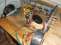
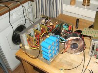
Finally the parts arrived, and yesterday I modified the PSU.
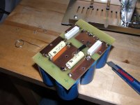
Enclosed are the immages of the teardown, capacitor card with "split" resistors and bypas caps added, and the new rectifier made from the super-de-luxe 60A fast& soft recovery diodes.
Completed the assembly today, and powered up.
On the side of the split capacitor bank connected to the rectifier, I measured about 400mV of ripple.
On the other side, i.e. in the part of the capacitor bank on the other side of the split-resistors where the amps are connected, I measured 50mV ripple.
This was with all thre amplifier cards drawing about 200 mA each of idle-current.
That's what I would call a significant improvement!
Next:
Output noise measurements..
Attachments
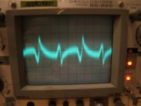
And here's the first measurements..
Scope set at 2mv/ div. and all the amplifier connected to the x-over card including sifnal screen.
Not too much improvement from previous set-up.
What is interresting to note, is the difference between the first amp and the second, and how that difference is reduced when I insert the strip of mu-metal behind the x-over card.
The output from the third amp is quite messy, anb the mu-metal didnæt make much difference here..
The third amp is situated closest to the transformer, and the first one furthest away.
Now lets see what some alternative grounding approaches will do..
Attachments
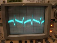
Now, the first measurement shows the x-over card grounded through one signal screen only measured on the first channel.
Improvement here, but no change to speak of on amp 2 and 3.
The second immage shows the x-over card grounded from the PSU star-point and no screen ground connection.
This is quite noisy and not quite what I expected..
Perhaps I should try and ground the screens on the x-over card an disconnect the screens from the amp cards?
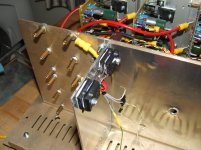
Now, after the rebuild, it became easier to move the transformer, so I managed to lift it out of the chassis.
As you can se from the immage, I couldn't move it that much but now it was at least not sitting virtually next to the x.over board.
This didn't really make much difference. When grounding the x-over card from the starpoint, there was slightly less noise on the scope, but not a change I would call significant as such.
Attachments
Hmmm..
This is difficult to make any sense of...
PSU has been improved with greatly reduced ripple.
Correct starpoint topologuy has been implemented.
Could it be difference between the wires connecting the amplifier cards to the PSU?
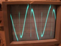
As can be seen from the scope noise measurements, it is allways the third amp-card which has the noisiest output. This card allso has the longest wires from the PSU, especially the 0V wire which is over twice as long as the others.
Any comments??
This is difficult to make any sense of...
PSU has been improved with greatly reduced ripple.
Correct starpoint topologuy has been implemented.
Could it be difference between the wires connecting the amplifier cards to the PSU?
As can be seen from the scope noise measurements, it is allways the third amp-card which has the noisiest output. This card allso has the longest wires from the PSU, especially the 0V wire which is over twice as long as the others.
Any comments??
Elbert; Sorry it is still give you a headache after all that work, but now you know what its not. It looks like you are passing power thrue the bulkhead from the cap board to the other side for the amps. That may not be the best thing. I see some jumpers on the cap board side under the stand offs? It may be posible you are getting some voltage differentials through all those different metals. Brass stand offs, aluminum bulkhead, and copper wires all have differant resistances. I think it more likely to cause problem than the lenghts of the wires going to the amps. Can you try to wire the outputs from the cap board strait to the amps for testing? Andy
OK Something from left field (and I may have already asked this before). Have you tried completely disconecting the PS from the crossover card, but leaving everything else connected? and doing measurements.
I'm just wondering whether you are getting some amp ps current flowing back through your xover psu rectifier and transformer (since the zero volts of each PS is effectively coupled via the signal cables)....
Tony.
I'm just wondering whether you are getting some amp ps current flowing back through your xover psu rectifier and transformer (since the zero volts of each PS is effectively coupled via the signal cables)....
Tony.
Last edited:
Elbert; Sorry it is still give you a headache after all that work, but now you know what its not. It looks like you are passing power thrue the bulkhead from the cap board to the other side for the amps. That may not be the best thing. I see some jumpers on the cap board side under the stand offs? It may be posible you are getting some voltage differentials through all those different metals. Brass stand offs, aluminum bulkhead, and copper wires all have differant resistances. I think it more likely to cause problem than the lenghts of the wires going to the amps. Can you try to wire the outputs from the cap board strait to the amps for testing? Andy
Well, everything has a resistance, so wether its copper or aluminium shouldn't make anny difference.. all the connections from the rectifier to the bulkhead connection points are now of equal length and far less complicated than before, so this is not my first suspect..
I'm leaning more towards the wiring to the amplifier cards, they are different lenghts and not twisted properly due to the space available and the stiffness/ thickness of the wires..
I'll try do do some measurements focused on this in the afternoon..
Tony, have tried leaving the X-over card dead, i.e disconnected from it's PSU, no luck there either..
OK that rules that out then Another thought I had on the way home from the station, you mentioned that amp # 3 was the worst, how did it compare if it was the only one running? That should tell you whether the PS wiring is making a difference for that amp compared to the one with the best performance.
I assume you have checked all three of them in isolation.
I remembered my first amp that I ever built this evening, around 27 years ago. It had a most objectionable hum when I first got it working. The back panel was Masonite but it had a foil coating on it. The input RCA jacks were not insulated and the foil connecting the earth's of the two input shields caused massive hum. As soon as I isolated the the input jacks the hum went away. There is a pic of that amp (in the ugly looking amp thread) Actually looking at that picture the problem could have been an earth loop between input and speaker returns (the speaker connectors were also rca jacks).
I think one of the things you tried before was just connecting the shields of the amp inputs at the XO end without connecting to the x-over board right? and it had the same effect as if they were connected to the crossover, if I remember correctly?
Have you tried not connecting the shields at the amp end of the signal cable and instead running a wire from the shield at the amp end (for each amp) direct to the common 0V point on the PSU board where the amp 0V connections terminate?
Tony.
Another thought I had on the way home from the station, you mentioned that amp # 3 was the worst, how did it compare if it was the only one running? That should tell you whether the PS wiring is making a difference for that amp compared to the one with the best performance. I assume you have checked all three of them in isolation.
I remembered my first amp that I ever built this evening, around 27 years ago. It had a most objectionable hum when I first got it working. The back panel was Masonite but it had a foil coating on it. The input RCA jacks were not insulated and the foil connecting the earth's of the two input shields caused massive hum. As soon as I isolated the the input jacks the hum went away. There is a pic of that amp (in the ugly looking amp thread) Actually looking at that picture the problem could have been an earth loop between input and speaker returns (the speaker connectors were also rca jacks).
I think one of the things you tried before was just connecting the shields of the amp inputs at the XO end without connecting to the x-over board right? and it had the same effect as if they were connected to the crossover, if I remember correctly?
Have you tried not connecting the shields at the amp end of the signal cable and instead running a wire from the shield at the amp end (for each amp) direct to the common 0V point on the PSU board where the amp 0V connections terminate?
Tony.
Last edited:
Awesome Amp there Tony, a case study in utilitarian budget design!
Yes, In isolation, all the amps are fine, it's when I connect them that things start getting problematic...
When re-doing the PSU, I connected the chassis to the star-point, simply by not insulating the 0-V bulkhead penetration from the caps.
Following that, I insulated the RCA input from the chassis. Allso, the speaker - terminals are insulated from the chassis.
regarding the alternating shield connection, you are right Tony.
I have not tried your suggestion for connecting the screens to the starpoint with a dedicated wire as such..
When I had the screens connected at the x-over card and the card connected to the star point with a dedicated wire, that would effectively be the same thing, and that gave a lousy result..
To get to the bottom of the PSU wiring, I can try the following this evening..
1. Measure with the scope between the 0V connections on the amp cards to see if any voltage potentials develops over the wires from the star-point.
2. Use the PSU wires from amp3 to power amp 1 or two and see if the problem with amp 3 follows the wiring or not.
Last edited:
measuring hum or buzz voltage across a wire may give a (near) zero reading.
The amplifier increases the signal by it's gain.
If the hum and/or buzz is 2.1mVac at the output and you have a gain of 30times (+29.5dB) then the input referred interference is ~70uVac. That could be the total over a group of wires. Finding the wire with the worst signal that is very likely to be <100uVpp is not going to be easy.
I know you don't like it, but you are getting closer to stripping the amp down.
Connect ONE channel Power Amp and measure the output noise with the input to the Power Amp shorted and with the input open.
If that is satisfactory, then add on ONE more piece and measure again.
Hi Elbert, maybe I'm not understanding what you did but maybe a picture will help with what I am talking about.... did you leave one end of the sheild completely floating and ran a wire to the star point from the crossover?
I've drawn once again how I think you now have things connected. Only showing 0V wires between the amps, PSU and XO card. I believe you have a loop between the 0V on the PSU and through the XO card between the amps. Whether this is significant or not I'm uncertain, but if you break the shield at the points where I put an x, and extend it to the PSU star point (represented by the dotted lines) then It should break the loop between the amp cards, as the only common connection they will have will be the connection to the star point. The signal ground will be via the potentially "dirty" PSU star point though...
I've drawn an extra feint line with arrows on it to indicate where there may be some loops between amps, not sure if this is realistic but seemed a possibility.
Although this suggestion seems very similar to what you posted that you have tried and was worse, the difference (I think) is that the shield is maintained end to end.
Tony.
Attachments
- Status
- This old topic is closed. If you want to reopen this topic, contact a moderator using the "Report Post" button.
- Home
- Amplifiers
- Power Supplies
- A Grounding challenge , please help..