Hi Elbert, I think we need to establish (for everyones benefit) what has been ruled out!
You have tested with the XO PS completely disconnected and NO CHANGE
You have tested just connecting the shields together of the inputs to the amp (SAME as when connected to XO Board).
correct me if I am wrong")
From this I think we can safely say that the problem is isolated to the amps themselves not liking having their input side earths connected. I think you can safely ignore anything to do with the XO side of the circuit until you have fixed that issue
Tony.
You have tested with the XO PS completely disconnected and NO CHANGE
You have tested just connecting the shields together of the inputs to the amp (SAME as when connected to XO Board).
correct me if I am wrong
From this I think we can safely say that the problem is isolated to the amps themselves not liking having their input side earths connected. I think you can safely ignore anything to do with the XO side of the circuit until you have fixed that issue
Tony.
Tony,
You are not wrong, hence I will not correct you in any way!
A good point to establish this and rule out the X-over card as such!
This is allso why I think the last posts and input regarding modifications of the actual amplifier cards is very interresting!
So I only hope I can get my head arround that and identify and implement a solution that works.
Elbert I just thought of something else, you could have an earth loop between your scope and your amp! I have an earth loop breaker on my amp so it isn't a problem, however when I connected up an earthed source whilst I had the scope connected I suddenly got a lot of hum. Removing the scopes earth probe the hum disappeared. Have you actually listened for hum since you made the mod, or only used the scope?
Tony.
Tony.
Tony,
That's a really interresting observation!
No, I have not listened, only measured since the modification.
Having said that, the variations I get when doing different measurement would immediately suggest to me that "stuff" is actually going on with the amp, but I can not afford to put your concern aside without further investigation!
I will check for this tomorrow! (have cleared the kitchen-table lab for breakfast tomorrow!)
No progress on the chipamp... have been working on finalising the layout of my LM317 dual rail supply. I Unfortunately lost the last changes to the layout when I thought I'd saved the latest version to the hard drive but had actually saved to my usb key (and copied the HD copy to the usb key) but it is an opportunity to re-think and do it better
The noise on the chipamp is very minor, so I'm not concentrating on it too much at the moment, but after seeing NO noise is possible it is something I'd like to address, and will do so before tackling the PSU for the playmaster.
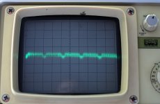
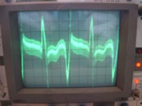
Attached is the measurement of the noise on the output of the chipamp scope was set to 5mv/division (max res of my scope) and 5ms/division I can only hear this with my ear right against the speaker.
Tony.
but it is an opportunity to re-think and do it better The noise on the chipamp is very minor, so I'm not concentrating on it too much at the moment, but after seeing NO noise is possible it is something I'd like to address, and will do so before tackling the PSU for the playmaster.
Attached is the measurement of the noise on the output of the chipamp scope was set to 5mv/division (max res of my scope) and 5ms/division I can only hear this with my ear right against the speaker.
Tony.
Attachments
Sorry about the lost layout, such things are really annoying!
Hope you are able to backtrack and perhaps improve further?
The output from your chip-amp looks very good, at least compared to the gargage I'm getting, so any further improvements might be tough to wring out I guess..
Hope you are able to backtrack and perhaps improve further?
The output from your chip-amp looks very good, at least compared to the gargage I'm getting, so any further improvements might be tough to wring out I guess..
you might be right with regards to reducing the noise further, but as this amp has two PS's running off one pair of secondaries (though single rectifier per PS unlike your oriiginal two rectifiers per pe) I thought it was worth trying with only one PS driving both channels to see if it made a difference.
I was rather unhappy that I lost my changes (as I was quite happy with what I came up with), but it did still have room for improvement and I'm going to take a different approach to re-do it so not all bad
Tony.
PS. yes I think looking at the mods to the amp as suggested are a good approach. don't get distracted too much by my scope observations though it is something to consider...
I was rather unhappy that I lost my changes (as I was quite happy with what I came up with), but it did still have room for improvement and I'm going to take a different approach to re-do it so not all bad
Tony.
PS. yes I think looking at the mods to the amp as suggested are a good approach. don't get distracted too much by my scope observations
though it is something to consider...
Last edited:
Reading up some more and trying to absorb the concept of implementing a "disconnect" or "ground break" resistor (as it is refered to as in Bob Cordells book), I think I now understand that adding the resistor in the input network allone may not work.
If the resistor is only implemented here, the negative feedback loop shunt resistor (R22) wil be referenced to "another" ground, and the doube differential input pair will have two ground references. I can't predict what that will do, but I see that it dosen't sound like a good idea!
This was perhaps not to evident to me from the schematic cutout that John kindly provided, from that I sort of got the impression that connecting the input ground to circuit ground with a 10 Ohm resistor was it, more or less..
In Bob Cordells amplifier book, section 18.4, page 380, describes how a ground breaker resistor is implemented and that the negative feedback shunt resistor is referenced to the "new" input ground node.
To my understanding, this is exactly what JCX described:
looks like your amp boards could be modified - you have to "lift" R22 gnd leg and solder a low ~ 10 to maybe 50 Ohm R in series to the board gnd (the hole you just removed R22 gnd lead from should do)
this lowers loop gain when nothing is attached, but by a very small amount - if the amp were really marginal it could reduce stability - be sure the new resistor is secure - the amp will almost certainly oscillate if the connections are bad or break
"the new node is your "differential gnd input" that gets wired to the Xover board gnd with the signal_gnd wire twisted with that channel's signal"
So far so good..
But the next thing JCX suggests is this:
"you would also add a new 12K (if I read the value right) R from R3 to the Amp board gnd - ideally to the "same" electrical "point" as the 10 Ohm added R, but don't create shorting problems or make a big loop or antenna trying to stretch the lead too far
this forms a divider that ~ turns your amp into a "single op amp, 4 R differential amplifier" the ratio should match the feedback gain ratio (with the added ~10 Ohms assumed to be shorted out )
the added 12K does raise the lower frequency corner with the 2.2 uF input C - to ~7Hz - not a problem at all on the higher frequency outs, if trying for really low output on the woofer amp board you might increase the cap value
the added 12 KOhm also lowers the input impedance and level matching pots in series with the XO op amp outputs will upset the division ratio"
I can't find anything on this related to ground breaker resistors in Bob's book, and I'm not really sure what it does..
"turns your amp into a "single op amp, 4 R differential amplifier" what does this mean in practice, and why do I need to do this in addition to adding the ground break resistor??
I must seem like a right idiot posting such questions on what Is obviously self evident to others, but this is new teritory and a bit of a learning curve for me, so please forgive me if I need some spoon feeding to get this in to my head!
Allso, this is taking me towards the point where I start messign with the circuitry of an amp someone else with knowledge of things has designed, so I really need to make sure I understand what's going on and that it will work without upsetting a lot of other things..
If the resistor is only implemented here, the negative feedback loop shunt resistor (R22) wil be referenced to "another" ground, and the doube differential input pair will have two ground references. I can't predict what that will do, but I see that it dosen't sound like a good idea!
This was perhaps not to evident to me from the schematic cutout that John kindly provided, from that I sort of got the impression that connecting the input ground to circuit ground with a 10 Ohm resistor was it, more or less..
In Bob Cordells amplifier book, section 18.4, page 380, describes how a ground breaker resistor is implemented and that the negative feedback shunt resistor is referenced to the "new" input ground node.
To my understanding, this is exactly what JCX described:
looks like your amp boards could be modified - you have to "lift" R22 gnd leg and solder a low ~ 10 to maybe 50 Ohm R in series to the board gnd (the hole you just removed R22 gnd lead from should do)
this lowers loop gain when nothing is attached, but by a very small amount - if the amp were really marginal it could reduce stability - be sure the new resistor is secure - the amp will almost certainly oscillate if the connections are bad or break
"the new node is your "differential gnd input" that gets wired to the Xover board gnd with the signal_gnd wire twisted with that channel's signal"
So far so good..
But the next thing JCX suggests is this:
"you would also add a new 12K (if I read the value right) R from R3 to the Amp board gnd - ideally to the "same" electrical "point" as the 10 Ohm added R, but don't create shorting problems or make a big loop or antenna trying to stretch the lead too far
this forms a divider that ~ turns your amp into a "single op amp, 4 R differential amplifier" the ratio should match the feedback gain ratio (with the added ~10 Ohms assumed to be shorted out )
the added 12K does raise the lower frequency corner with the 2.2 uF input C - to ~7Hz - not a problem at all on the higher frequency outs, if trying for really low output on the woofer amp board you might increase the cap value
the added 12 KOhm also lowers the input impedance and level matching pots in series with the XO op amp outputs will upset the division ratio"
I can't find anything on this related to ground breaker resistors in Bob's book, and I'm not really sure what it does..
"turns your amp into a "single op amp, 4 R differential amplifier" what does this mean in practice, and why do I need to do this in addition to adding the ground break resistor??
I must seem like a right idiot posting such questions on what Is obviously self evident to others, but this is new teritory and a bit of a learning curve for me, so please forgive me if I need some spoon feeding to get this
in to my head! Allso, this is taking me towards the point where I start messign with the circuitry of an amp someone else with knowledge of things has designed, so I really need to make sure I understand what's going on and that it will work without upsetting a lot of other things..
I had been incompetently tinkering with amplifiers for a few years before I joined this forum, mostly relying on the ESP site for plans and knowledge. The first amp that I built that actually worked had a ground loop hum and I set out to solve it. It led me to various sites and the Leach amp site was one of those. At first I used only the resistor but I learned my lesson when it burned out for no apparent reason and left me scratching my head for a day, trying to find the problem (it wasn't obviously burned). That is why the diodes are there.
John,
Seems like I am where you have once been!
I couldn't quire make it out from your schematic, but did you add that second resistor JCX suggested or anything like that?
"you would also add a new 12K (if I read the value right) R from R3 to the Amp board gnd - ideally to the "same" electrical "point" as the 10 Ohm added R, but don't create shorting problems or make a big loop or antenna trying to stretch the lead too far
this forms a divider that ~ turns your amp into a "single op amp, 4 R differential amplifier" the ratio should match the feedback gain ratio (with the added ~10 Ohms assumed to be shorted out )"
Time to get the scope out again...
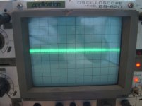
First I measured between the DC servo input andf the signal ground point.
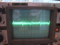
For amp1 this looked ok, for amp 2, I could see some ripple.
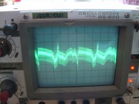
I then tried to measure between the servo input and signal input on respective cards.. Those measurements showed a lot of noise, but I think the first measurements between servo and gnd are the relevant ones..
Looking at the way I've wired and connected my servo/ protection cards, it is far from perfect..
Looks like I have some potential improvement I can try here before pursuing the ground break resistor option further..
First I measured between the DC servo input andf the signal ground point.
For amp1 this looked ok, for amp 2, I could see some ripple.
I then tried to measure between the servo input and signal input on respective cards.. Those measurements showed a lot of noise, but I think the first measurements between servo and gnd are the relevant ones..
Looking at the way I've wired and connected my servo/ protection cards, it is far from perfect..
Looks like I have some potential improvement I can try here before pursuing the ground break resistor option further..
Attachments
Very true Tony!
The brain is a fantastic device, whilst one is asleep it just churns away like some 50's cience-fiction problem solving computer!
I'm not sure if the wiring of the servo/protection cards is the final answer here, but the measurements shows that something is going on and probably contributing to the bigger picture to a greater or lesser degree.
- Status
- This old topic is closed. If you want to reopen this topic, contact a moderator using the "Report Post" button.
- Home
- Amplifiers
- Power Supplies
- A Grounding challenge , please help..